EP2784707A2 - Appareil de terminal portable et procédé d'affichage d'image médicale - Google Patents
Appareil de terminal portable et procédé d'affichage d'image médicale Download PDFInfo
- Publication number
- EP2784707A2 EP2784707A2 EP14157012.7A EP14157012A EP2784707A2 EP 2784707 A2 EP2784707 A2 EP 2784707A2 EP 14157012 A EP14157012 A EP 14157012A EP 2784707 A2 EP2784707 A2 EP 2784707A2
- Authority
- EP
- European Patent Office
- Prior art keywords
- image
- portable terminal
- terminal apparatus
- medical
- local
- Prior art date
- Legal status (The legal status is an assumption and is not a legal conclusion. Google has not performed a legal analysis and makes no representation as to the accuracy of the status listed.)
- Withdrawn
Links
Images


Classifications
-
- G—PHYSICS
- G06—COMPUTING OR CALCULATING; COUNTING
- G06T—IMAGE DATA PROCESSING OR GENERATION, IN GENERAL
- G06T7/00—Image analysis
- G06T7/0002—Inspection of images, e.g. flaw detection
- G06T7/0012—Biomedical image inspection
- G06T7/0014—Biomedical image inspection using an image reference approach
-
- G—PHYSICS
- G16—INFORMATION AND COMMUNICATION TECHNOLOGY [ICT] SPECIALLY ADAPTED FOR SPECIFIC APPLICATION FIELDS
- G16H—HEALTHCARE INFORMATICS, i.e. INFORMATION AND COMMUNICATION TECHNOLOGY [ICT] SPECIALLY ADAPTED FOR THE HANDLING OR PROCESSING OF MEDICAL OR HEALTHCARE DATA
- G16H40/00—ICT specially adapted for the management or administration of healthcare resources or facilities; ICT specially adapted for the management or operation of medical equipment or devices
- G16H40/60—ICT specially adapted for the management or administration of healthcare resources or facilities; ICT specially adapted for the management or operation of medical equipment or devices for the operation of medical equipment or devices
- G16H40/63—ICT specially adapted for the management or administration of healthcare resources or facilities; ICT specially adapted for the management or operation of medical equipment or devices for the operation of medical equipment or devices for local operation
-
- A—HUMAN NECESSITIES
- A61—MEDICAL OR VETERINARY SCIENCE; HYGIENE
- A61B—DIAGNOSIS; SURGERY; IDENTIFICATION
- A61B90/00—Instruments, implements or accessories specially adapted for surgery or diagnosis and not covered by any of the groups A61B1/00 - A61B50/00, e.g. for luxation treatment or for protecting wound edges
- A61B90/36—Image-producing devices or illumination devices not otherwise provided for
-
- H—ELECTRICITY
- H04—ELECTRIC COMMUNICATION TECHNIQUE
- H04N—PICTORIAL COMMUNICATION, e.g. TELEVISION
- H04N23/00—Cameras or camera modules comprising electronic image sensors; Control thereof
- H04N23/20—Cameras or camera modules comprising electronic image sensors; Control thereof for generating image signals from infrared radiation only
- H04N23/23—Cameras or camera modules comprising electronic image sensors; Control thereof for generating image signals from infrared radiation only from thermal infrared radiation
Definitions
- the present invention relates to a portable terminal apparatus and a medical image display method. More particularly, the present invention relates to a portable terminal apparatus and a medical image display method, in which an object in a body of a patient can be specified readily with good handlability.
- An image display apparatus for diagnosis is widely used in a medical field, and displays medical images or diagnostic images, such as X-ray images.
- medical imaging of a body of a patient is carried out, for example, X-ray imaging as radiographic imaging.
- the medical images obtained by the medical imaging are stored in an image server or server apparatus.
- the image display apparatus accesses the image server by use of a communication network such as a local area network (LAN), and acquires and displays the medical images.
- LAN local area network
- Various medical imaging apparatus for forming the medical image include a CT apparatus (computed tomography apparatus) for sectional imaging by use of X-rays, and an MRI apparatus (magnetic resonance imaging apparatus) for sectional imaging by use of magnetic resonance. It has been possible recently to form medical images of a whole body of a patient even in a short time owing to technical development of the CT and MRI apparatuses. In a practical flow of diagnosis, the body is imaged irrespective of his or her lesion. A plurality of the medical images for the body are stored. Then a required one of the medical images with an object (body part or anatomical region) for the diagnosis is read out and displayed on the image display apparatus.
- CT apparatus computed tomography apparatus
- MRI apparatus magnetic resonance imaging apparatus
- the image server stores combinations of the medical image and object information (body part information or anatomical region information) of the object in the body, such as a head, chest or abdomen. All of the medical images are cumulatively stored in relation to the whole of the body of each of various patients.
- the image display apparatus for the purpose of reading out the medical image, transmits a request to the image server together with the object information of a selected one of the objects.
- the image server responsively distributes or transmits the medical image to the image display apparatus in relation to the object specified by the request.
- a keyboard or button panel is used for inputting the keywords of the "head, chest or abdomen" to select the object.
- U.S. Pat. No. 7,769,602 (corresponding to JP-A 2005-296065 ) discloses a use of a schematic view of the body with divisions of the region in the object of the head, chest or abdomen.
- a pointer of a mouse is driven to click and select a portion in the schematic view.
- U.S. Pat. No. 7,769,602 it is possible to input command signals more easily and more directly than the specification method in the use of the keyboard.
- U.S. Pat.Pub. No. 2009/208,076 discloses a portable terminal apparatus for imaging diagnosis including a portable housing and a display panel disposed in front of the housing, in one form of the image display apparatus.
- the portable terminal apparatus has the display panel with a smaller size than that of the image display apparatus of an installed type. Although a menu image for the keyboard is displayed for the display panel as required, it is difficult to specify the object by manipulating the keyboard, because the display panel is remarkably small with a small size of the entirety of the keyboard and each alphanumeric elements. It is conceivable to combine the disclosure of U.S. Pat. No. 7,769,602 with the portable terminal apparatus, in which the schematic view of the body is displayed for specifying the object in place of the keyboard. However, the schematic view of the body must have a small size. Low handlability cannot be coped with due to the small size of the display panel.
- an obj ect of the present invention is to provide a portable terminal apparatus and a medical image display method, in which an object in a body of a patient can be specified readily with good handlability.
- a portable terminal apparatus for imaging diagnosis includes an object recognition unit for recognizing one object in a body for imaging diagnosis, so as to output object information of the object.
- An image acquisition device acquires a medical image from an image storage apparatus with relevancy to the object according to the object information.
- a display unit displays the acquired medical image.
- the object recognition unit includes an image sampling device for imaging the object in the body to create a local image.
- An image analyzer analyzes the local image in image analysis, to specify the object for outputting the object information.
- the image sampling device is an optical camera for creating an optical image.
- the image analyzer specifies the object by the image analysis of the optical image.
- the optical camera creates an optical body image of the body and the local image related to the object in the body.
- the image analyzer specifies the object by comparison between the optical body image and the local image.
- a storage device stores the medical image acquired by the image acquisition device and the local image from the optical camera.
- the medical image is constituted by plural medical images of two or more imaging modalities different from one another, and/or plural medical images of an imaging modality at two or more image dates different from one another.
- the image storage apparatus is an image server connected in communication network connection.
- the image sampling device is a thermal camera for creating an image of temperature distribution.
- the image analyzer specifies the object by the image analysis of the image of the temperature distribution.
- the thermal camera creates a body thermal image of the body and a local thermal image of the temperature distribution related to the object in the body.
- the image analyzer specifies the object by comparison between the body thermal image and the local thermal image.
- a storage device stores the medical image acquired by the image acquisition device and the local thermal image from the thermal camera.
- the medical image is constituted by plural medical images of two or more imaging modalities different from one another, and/or plural medical images of an imaging modality at two or more image dates different from one another.
- the image storage apparatus is an image server connected in communication network connection.
- a medical image display method for a portable terminal apparatus includes a step of recognizing one object in a body for imaging diagnosis, so as to output object information of the object.
- a medical image is acquired from an image storage apparatus with relevancy to the object according to the object information.
- the acquired medical image is displayed on the portable terminal apparatus.
- the object recognizing step includes imaging the object in the body with the portable terminal apparatus to create a local image.
- the local image is analyzed in image analysis, to specify the object for outputting the object information.
- a computer-executable program for controlling a portable terminal apparatus for imaging diagnosis includes a program code for selectively specifying one object in a body, so as to output object information.
- a region of the object is changeable according to a terminal position or terminal orientation relative to the body.
- a program code is for acquiring a medical image from an image storage apparatus with relevancy to the obj ect according to the obj ect information.
- a program code is for displaying the medical image.
- a user interface for controlling a portable terminal apparatus for imaging diagnosis includes a region for selectively specifying one obj ect in a body, so as to output object information.
- a region of the object is changeable according to a terminal position or terminal orientation relative to the body.
- a region is for acquiring a medical image from an image storage apparatus with relevancy to the object according to the object information.
- a region is for displaying the medical image.
- an object in a body of a patient can be specified readily with good handlability, because a medical image to be acquired remotely is determined according to the object specified in the body by handling the portable terminal apparatus.
- a remote diagnostic system is illustrated, and includes a portable terminal apparatus 10 and a server apparatus 32 or image server.
- the portable terminal apparatus 10 includes a terminal housing 21 of a portable form, and a display unit 22.
- the display unit 22 is disposed on a front side of the terminal housing 21, and is a liquid crystal panel of a touch panel structure.
- an optical camera 23 for image sampling of Fig. 3 is incorporated in the terminal housing 21.
- a lens system 23a or taking lens is disposed on the rear side of the terminal housing 21 as optics in the optical camera 23.
- the server apparatus 32 or image server as image storage apparatus is connected with the portable terminal apparatus 10 communicably by a communication network 31, such as a local area network (LAN) in the hospital facility.
- Medical images 17 or diagnostic images of a body 15 of a patient are remotely distributed from the server apparatus 32 upon access from the portable terminal apparatus 10, so that the display unit 22 of the portable terminal apparatus 10 displays one of the medical images 17.
- the server apparatus 32 stores the medical images 17 created by a medical imaging apparatus in a manner sorted by a patient ID (patients A and B and the like) as attribute information for recognition.
- An example of the medical imaging apparatus is a CT apparatus (computed tomography apparatus).
- the medical images 17 are sectional images.
- the CT apparatus images the whole of the body 15 in one sequence of imaging, to create an image group 16 or image series including a set of the plurality of the medical images 17 in relation to the body 15.
- object information is associated with each of the medical images 17 besides image data, and expresses objects such as a head, chest and abdomen of the body 15.
- the server apparatus 32 is provided by the portable terminal apparatus 10 with information of a request, which includes the patient ID for recognition of the patient, and object information of an object 15a (body part or anatomical region) in the body 15. According to the object information included in the request, the server apparatus 32 searches and reads the medical image 17 according to the object 15a specified with the object information from the image group 16 of the body 15. The server apparatus 32 transmits the medical image 17 to the portable terminal apparatus 10.
- the portable terminal apparatus 10 is constituted by installing an application program (AP) 30 in a communication apparatus or electronic apparatus.
- the application program 30 are an operating system (OS) and a control program for functioning the communication apparatus as a display apparatus.
- Examples of the communication apparatus are a cellular telephone, smart phone and the like.
- the terminal housing 21 of the portable terminal apparatus 10 includes not only the display unit 22 and the optical camera 23 but a button panel 24 with operation buttons, a CPU 25 as display control device, a memory 26, a storage device 27 and a communication interface 28.
- a data bus 29 interconnects those elements together with the display unit 22 and the optical camera 23.
- the storage device 27 is internal storage incorporated in the terminal housing 21. Examples of the storage device 27 are a hard disk drive (HDD), semiconductor memory and the like.
- the storage device 27 stores various data, for example, stores a control program and the application program 30 such as software for a console unit.
- the application program 30 includes a reading application for displaying personal information and medical chart information (document or text), and an image viewing application for displaying the medical images 17.
- the personal information has a patient name, patient ID and the like.
- the chart information includes a medical chart of the patient.
- the image viewing application is an application for remotely acquiring the medical images 17 from the server apparatus 32 and displaying the medical images 17 on the display unit 22.
- the image viewing application includes a program for the CPU 25 to execute in an object specification mode (body part recognition mode).
- the object specification mode is a mode for easily inputting the object specification from a doctor or user of the portable terminal apparatus 10.
- the chart information is acquired from a chart server apparatus (not shown) through the communication network 31. Thus, the chart information is input to the portable terminal apparatus 10 inclusive of the patient ID.
- information of an operation menu is displayed on the display unit 22.
- the memory 26 is a working memory with which the CPU 25 performs tasks.
- the CPU 25 loads the memory 26 with the control program read from the storage device 27, and controls various elements in the computer by processing according to the control program.
- the CPU 25 operates as a display control unit for controlling the display unit 22.
- the communication interface 28 is a network interface for controlling transmission to the communication network 31, such as a local area network (LAN).
- LAN local area network
- the optical camera 23 includes the lens system 23a and an imaging unit for forming a body image with visible light focused by the lens system 23a.
- the imaging unit include a CCD (charge coupled device) image sensor, CMOS (complementary metal oxide semiconductor) image sensor, and the like.
- the optical camera 23 While the imaging mode is set, the optical camera 23 repeatedly performs live imaging in which a live view image is created at a predetermined interval.
- the live view image formed by the live imaging is displayed on the display unit 22 in a real-time manner.
- the button panel 24 operates as a release button.
- still imaging is started.
- the optical camera 23 forms a still image focused by the lens system, and outputs the still image to the storage device 27.
- the still image is an optical image of which the number of pixels is higher than that of the live view image.
- the optical camera 23 for image sampling is utilized for inputting object specification upon startup of the image viewing application.
- an imaging mode is set to start the optical camera 23 for the live imaging.
- an object to be imaged by the optical camera 23 is changed according to a change in the relative position between the terminal housing 21 and the body 15, namely, according to a position of directing the terminal housing 21 to a region in the body 15.
- a still image is created by directing the lens system 23a of the terminal housing 21 to a region in the body 15, for example, the chest, then an optical image of the chest is written to the storage device 27.
- the portable terminal apparatus 10 automatically recognizes the chest included in the created optical image according to the optical image stored in the storage device 27.
- the CPU 25 comes to include an image acquisition device 35, and an image analyzer 37a.
- the optical camera 23 and the image analyzer 37a are combined to constitute an object recognition unit 37.
- An optical local image 42 is analyzed by the image analyzer 37a, which recognizes an object imaged in the optical local image 42, and outputs object information of the object to the image acquisition device 35.
- the image acquisition device 35 creates a request of distribution according to the object information from the image analyzer 37a, and sends the request to the server apparatus 32.
- the optical camera 23 operates in the object specification mode (body part recognition mode) as illustrated in Fig. 5 .
- Still images including an optical body image 41 of the whole of the body 15 and the optical local image 42 of the object 15a required by a doctor are formed.
- the optical body image 41 and the optical local image 42 are written to the storage device 27.
- the image analyzer 37a reads the optical body image 41 and the optical local image 42 from the storage device 27.
- the image analyzer 37a processes the optical body image 41 and the optical local image 42 for extraction of the profiles, and compares the profiles with one another.
- the image analyzer 37a carries out the processing for the checking the profile, and extracts a region where a profile in the optical local image 42 coincides with a profile in the optical body image 41.
- Data for the image viewing application include reference data expressing relationships of various profile lines with the head, chest, abdomen, lower abdomen, arms, legs and the like as objects. Although a size of the body is different between patients, the shapes of the head, chest, abdomen, lower abdomen, arms, legs and the like are common. Therefore, the reference data can be prepared suitably.
- the image analyzer 37a refers to the reference data, and detects one of the objects in the optical body image 41 with which the profile in the optical local image 42 coincides. In this manner, the image analyzer 37a carries out the object specification. The image analyzer 37a outputs a result of the object specification to the image acquisition device 35 as object information.
- the optical local image 42 to be input to the image analyzer 37a is changed.
- the object recognized by the image analyzer 37a is changed.
- the image acquisition device 35 transmits a request to the server apparatus 32 inclusive of the object information, and remotely acquires the medical image 17 relevant to the object specified with the object information from the server apparatus 32.
- the medical image 17 being acquired is displayed on the display unit 22.
- a doctor or operator uses the portable terminal apparatus 10 in case a patient sees him or her for consultation.
- the doctor views the medical image 17 as a result of imaging of the body 15.
- the doctor inputs information of a selected object (body part or anatomical region) for the portable terminal apparatus 10 to display one of the medical images 17 relevant to the symptoms of the body 15.
- the object specification mode body part recognition mode
- the portable terminal apparatus 10 starts live imaging with the optical camera 23.
- the doctor views a live view image on the display unit 22 while the lens system 23a of the terminal housing 21 is directed to the body 15, and positions the terminal housing 21 to frame the entirety of the body 15.
- the button panel 24 is manipulated to form the optical body image 41 (step S51 and Fig. 6B ).
- the optical body image 41 is written to the storage device 27.
- the terminal housing 21 is positioned and directed to the object 15a in the body 15 in relation to the request of transmission (step S52). Assuming that the object 15a is a chest, the terminal housing 21 is directed to the chest.
- the doctor checks the live view image of the chest on the display unit 22, and manipulates the button panel 24. Consequently, the optical local image 42 as a still image of the chest is created and written to the storage device 27 (step S53 and Fig. 6C ).
- the image analyzer 37a compares the optical body image 41 with the optical local image 42 after outputting to the storage device 27 (step S54), and detects an object in the optical local image 42 according to a result of the comparison to specify the object (step S55).
- the image analyzer 37a outputs the object information to the image acquisition device 35. Thus, the inputting operation for the object specification is carried out.
- the image acquisition device 35 transmits the request to the server apparatus 32 (step S56), the request including the object information and patient ID.
- the server apparatus 32 searches and reads the medical image 17 relevant to an object coinciding with an object of the object information according to the request, and transmits the medical image 17 to the portable terminal apparatus 10.
- the portable terminal apparatus 10 upon remotely receiving the medical image 17 (step S57) drives the display unit 22 to display the medical image 17 (step S58 and Fig. 6D ).
- the portable terminal apparatus 10 can input signals for object specification only by imaging the whole body 15 and by imaging the object 15a in the body 15 relevant to requirement of data transmission in a suitable orientation of the portable terminal apparatus 10. It is unnecessary to manipulate an user input field or keyboard with the display unit 22 with a display image of a shape of a human body as disclosed in U.S. Pat.Pub. No. 2009/208,076 (corresponding to JP-A 2009-189541 ). As the display unit 22 of the portable terminal apparatus 10 has a small size of the display image, the display unit 22 is difficult to manipulate because of the small user input field. However, it is possible in the invention to keep high operability because of no requirement of a small user input field.
- the body 15 it is possible according to this manipulating method for the body 15 to recognize a specific object in the medical image 17 to be displayed by use of the terminal position of the portable terminal apparatus 10.
- the object imaged in the medical image 17 can be clarified distinctly. Explanation of a doctor with the medical image 17 can be easily understood by a patient upon medical notification of diagnostic information.
- the optical body image 41 is formed in addition to the optical local image 42, so that an object in the optical local image 42 is detected by comparison between the optical local image 42 and the optical body image 41.
- the optical body image 41 may not be formed.
- there are common features in a profile line of a human body irrespective of minor differences between individuals.
- the optical body image 41 is utilized to facilitate comparison of the optical body image 41 with the optical local image 42, because the shape, pattern or the like of the clothes is also imaged in the optical body image 41 and in the optical local image 42.
- the precision in the detection can be high. Therefore, it is preferable to form the optical body image 41.
- the information of the relative position between the terminal housing 21 of the portable terminal apparatus 10 and an object in the body 15 also includes information of a change of a terminal orientation of the portable terminal apparatus 10 relative to the body 15 as well as a relative height of the portable terminal apparatus 10 to the body 15.
- the terminal housing 21 can be inclined while the height of the portable terminal apparatus 10 is unchanged, to change a direction of the lens system 23a.
- an imaging area can be changed.
- the terminal orientation of the terminal housing 21 is directed downwards by positioning the portable terminal apparatus 10 at a height of a head of the body 15. It is possible to direct the lens system 23a to a chest of the body 15.
- FIG. 7 A second preferred embodiment is described by referring to Figs. 7-10D .
- the portable terminal apparatus 10 of the first embodiment is repeated but with a difference in which a thermal camera 61 or thermosensor camera is used for image sampling instead of the optical camera 23.
- Elements similar to those of the above embodiment are designated with identical reference numerals.
- the thermal camera 61 is a camera for forming an image by visualizing temperature distribution in an imaging area.
- the portable terminal apparatus 60 has a terminal housing 60a.
- the thermal camera 61 has temperature sensors (not shown), which corresponds to the lens system 23a of the optical camera 23 and disposed on the portable terminal apparatus 60 in a similar manner to the lens system 23a.
- temperature sensors not shown
- temperature of a human body is not uniform but different between various objects (body parts or anatomical regions). According to a known temperature distribution, temperature of a head and chest is relatively high. Temperature of an abdomen, hands and feet is relatively low.
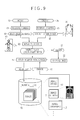
- it is possible to specify an object of a local thermal image 66 by comparison of a body thermal image 65 and the local thermal image 66 in image analysis for temperature distribution in Fig. 9 .
- the temperature distribution in each of the thermal images is expressed with a red color for a relatively high temperature, and with colors or orange, yellow, green and blue for lower temperature decreasing in this sequence.
- the head and the chest are in the red color.
- Objects continuing from those are in the colors coming near to blue in a sequence toward distal ends of the abdomen, hands and feet.
- the CPU 25 in the portable terminal apparatus 60 operates with an image analyzer 62 in the object recognition unit, and the image acquisition device 35. See Fig. 8 .
- the image analyzer 62 extracts patterns of temperature distributions of the body thermal image 65 and the local thermal image 66 (see Fig. 9 ) according to the image analysis, the body thermal image 65 being formed from the whole of the body 15, the local thermal image 66 being formed from the object 15a in the body 15.
- the distribution pattern from the local thermal image 66 is compared with that from the body thermal image 65, to detect an object included in the local thermal image 66. Then object information is obtained from the result of the comparison.
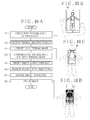
- the operation of the above construction is described by referring to the flow chart in Figs. 10A-10D .
- the portable terminal apparatus 60 is used for a doctor or operator in the health care service of the body 15 in a similar manner to the portable terminal apparatus 10. He or she inputs information for object specification to drive the portable terminal apparatus 60 for displaying the medical image 17 of the object related to the diagnosis or treatment.
- the portable terminal apparatus 60 starts live imaging with the thermal camera 61.
- the doctor directs the terminal housing 60a to the body 15, observes the live view image on the display unit 22, positions the terminal housing 21 in a manner framing the whole of the body 15, and manipulates the button panel 24 to form the body thermal image 65 (step S71 and Fig. 10B ).
- the body thermal image 65 is written to the storage device 27.
- the terminal housing 21 is directed to a region of the object 15a in the body 15 of which the doctor wishes to receive a medical image (step S72).
- the terminal housing 21 is directed to the chest which is the object 15a. He or she manipulates the button panel 24 after checking the live view image of the chest on the display unit 22.
- a still image of the chest is formed by way of the local thermal image 66, which is written to the storage device 27 (step S73 and Fig. 10C ).
- the image analyzer 62 compares the body thermal image 65 with the local thermal image 66 after outputting to the storage device 27 (step S74), and recognizes the object within the local thermal image 66 according to a result of the comparison (step S75).
- the image analyzer 62 outputs object information to the image acquisition device 35. Thus, the inputting operation for the object specification is carried out.
- the image acquisition device 35 transmits the request to the server apparatus 32 (step S76), the request including the object information and patient ID.
- the server apparatus 32 searches and reads the medical image 17 relevant to an object coinciding with that of the object information according to the request, and transmits the medical image 17 to the portable terminal apparatus 60.
- the portable terminal apparatus 60 upon remotely receiving the medical image 17 (step S77) drives the display unit 22 to display the medical image 17 (step S78 and Fig. 10D ).
- the object imaged by the thermal camera 61 is changed with a change in the relative position (terminal position or terminal orientation) of the terminal housing 60a of the portable terminal apparatus 60 to the body 15.
- the local thermal image 66 for input to the image analyzer 62 is changed.
- the object recognized by the image analyzer 62 is changed.
- the body thermal image 65 may not be formed in a manner similar to the first embodiment.
- the temperature distribution image of a standard distribution of a human body is used for comparison with the body thermal image 65.
- some specificity occurs in the temperature distribution between individuals. It is preferable to form the body thermal image 65 for comparison even in the second embodiment for the purpose of higher precision in the detection in a manner similar to the first embodiment.
- the optical local image or local thermal image can be stored in the storage device 27 or storage medium in the terminal apparatus as images obtained in the object specification in addition to the medical image 17. It is possible to save time or operation for acquiring the optical local image or local thermal image again. Also, selection of the optical local image or local thermal image can be linked with reading of the medical image 17 for a corresponding object from the storage device 27 upon displaying the medical image 17. Assuming that the medical image 17 is a sectional image, it may be difficult exactly to recognize an object in the medical image 17 with the appearance, such as a chest or abdomen. However, it is comparatively easy to recognize an object in the optical local image or local thermal image in comparison with sectional images. Accordingly, the redisplay of the medical image 17 can be quickened efficiently by storing the optical local image or local thermal image in the storage device 27 in addition to the medical image 17.
- the medical image 17 For the purpose of more rapid redisplay of the medical image 17, it is preferable to store relationship information of the optical local image and the local thermal image to the medical image 17.
- the medical image 17 can be searched according to the relationship information. It is unnecessary to recognize an object by image analysis of the optical local image and the local thermal image.
- the images formed by the optical camera 23 or the thermal camera 61 are used for the object specification.
- other methods for the object specification can be used.
- the body 15 wear a special medical garment for object specification.
- Storage devices are attached to the medical garment, are positioned at various parts including a head, chest, abdomen, arms and legs, and store an object location (body part recognition information).
- the storage devices are RFID tags (radio frequency identification tags).
- An RFID tag at the head stores an object location (body part recognition information) of the head.
- An RFID tag at the chest stores an object location of the chest.
- a sensor is disposed on the portable terminal apparatus for reading the RFID tags.
- the sensor in the terminal apparatus reads the object location (body part recognition information) of the head.
- the sensor in the terminal apparatus reads the object location of the chest. It is possible to change a region of the object to be recognized by the terminal apparatus according to changes in the relative position between the body 15 and the terminal apparatus.
- an extra display panel can be additionally used for displaying the same image as the display unit 22.
- multi-screen display is possible by use of a plurality of display panels separate from the display unit 22.
- the display unit 22 can be mainly used by a doctor and the extra display panel can be specially used by the patient for visual checking. Viewing the medical image 17 can be facilitated both for the doctor and for the patient owing to the separate assignment of the display panels.
- the image storage device for the medical images 17 is the server apparatus 32 in connection with the communication network 31.
- a image storage device can be an internal storage device in the terminal housing 21.
- the medical images 17 are CT images according to the above embodiments, but can be MRI images, X-ray images, endoscope images and the like formed by any one of various imaging modalities.
- a set of the medical images 17 can a combination of images of two or more different imaging modalities, such as CT images and MRI images.
- a set of the medical images 17 can be a combination of images of two or more different image dates.
- a set of the medical images 17 can be a combination of images of two or more different imaging modalities and two or more different image dates.
- examples of the object are the head, chest, abdomen and the like.
- an object (body part or anatomical region) in the body according to the invention can be a larger object such as an upper half body, and a smaller object such as a shoulder, knee and the like.
- the portable terminal apparatus is mobile, and connected to the server apparatus by the network wirelessly with the communication interface.
- the portable terminal apparatus of the invention can be an electronic apparatus of a portable size connected to the server apparatus in a wired manner directly by use of a connector without the network.
- a manual input device can be manipulated to select one of medical images for use, such as a key, joystick, mouse, touch pad and the like.
- At least one reference local image is stored in a memory for each of the various objects or body parts.
- the local image can be compared with the reference local image to specify an object to be diagnosed.
Landscapes
- Health & Medical Sciences (AREA)
- Engineering & Computer Science (AREA)
- Biomedical Technology (AREA)
- General Health & Medical Sciences (AREA)
- Medical Informatics (AREA)
- Public Health (AREA)
- Life Sciences & Earth Sciences (AREA)
- Surgery (AREA)
- Nuclear Medicine, Radiotherapy & Molecular Imaging (AREA)
- Multimedia (AREA)
- Signal Processing (AREA)
- Heart & Thoracic Surgery (AREA)
- Veterinary Medicine (AREA)
- Epidemiology (AREA)
- Primary Health Care (AREA)
- Animal Behavior & Ethology (AREA)
- Molecular Biology (AREA)
- Toxicology (AREA)
- Business, Economics & Management (AREA)
- General Business, Economics & Management (AREA)
- Oral & Maxillofacial Surgery (AREA)
- Pathology (AREA)
- Theoretical Computer Science (AREA)
- General Physics & Mathematics (AREA)
- Physics & Mathematics (AREA)
- Computer Vision & Pattern Recognition (AREA)
- Quality & Reliability (AREA)
- Radiology & Medical Imaging (AREA)
- Measuring And Recording Apparatus For Diagnosis (AREA)
- Apparatus For Radiation Diagnosis (AREA)
- Image Processing (AREA)
- Image Analysis (AREA)
- Medical Treatment And Welfare Office Work (AREA)
Applications Claiming Priority (1)
| Application Number | Priority Date | Filing Date | Title |
|---|---|---|---|
| JP2013062425A JP5698293B2 (ja) | 2013-03-25 | 2013-03-25 | 携帯型医用画像表示端末及びその作動方法 |
Publications (2)
| Publication Number | Publication Date |
|---|---|
| EP2784707A2 true EP2784707A2 (fr) | 2014-10-01 |
| EP2784707A3 EP2784707A3 (fr) | 2015-01-21 |
Family
ID=50280125
Family Applications (1)
| Application Number | Title | Priority Date | Filing Date |
|---|---|---|---|
| EP14157012.7A Withdrawn EP2784707A3 (fr) | 2013-03-25 | 2014-02-27 | Appareil de terminal portable et procédé d'affichage d'image médicale |
Country Status (3)
| Country | Link |
|---|---|
| US (1) | US20140285647A1 (fr) |
| EP (1) | EP2784707A3 (fr) |
| JP (1) | JP5698293B2 (fr) |
Families Citing this family (7)
| Publication number | Priority date | Publication date | Assignee | Title |
|---|---|---|---|---|
| US20150017613A1 (en) * | 2013-07-09 | 2015-01-15 | Lee Weinstein | Integrated health measurement and food service system |
| US20160063320A1 (en) * | 2014-08-29 | 2016-03-03 | Susan Liu | Virtual body scanner application for use with portable device |
| US10042078B2 (en) * | 2015-02-27 | 2018-08-07 | The United States of America, as Represented by the Secretary of Homeland Security | System and method for viewing images on a portable image viewing device related to image screening |
| DE102015104768B4 (de) * | 2015-03-27 | 2023-03-16 | Bundesdruckerei Gmbh | Zugangssystem mit Personenerkennungsvorrichtung |
| JP6181893B1 (ja) * | 2017-03-31 | 2017-08-16 | 株式会社Cygames | 閲覧確認のためのシステム、携帯端末装置、サーバ、プログラム及び方法 |
| CN109712691B (zh) | 2017-10-25 | 2021-07-23 | 商之器科技股份有限公司 | 转换行动装置显示器成医疗影像显示用系统及方法 |
| KR102654367B1 (ko) * | 2023-09-27 | 2024-04-03 | 주식회사 일렉필드퓨처 | 포터블 엑스레이 촬영 장치 |
Citations (2)
| Publication number | Priority date | Publication date | Assignee | Title |
|---|---|---|---|---|
| JP2005296065A (ja) | 2004-04-06 | 2005-10-27 | Konica Minolta Medical & Graphic Inc | 医用画像生成システム及び医用画像生成方法並びに表示制御プログラム |
| US20090208076A1 (en) | 2008-02-14 | 2009-08-20 | Fujifilm Corporation | Medical network system, and image-interpretation support apparatus and method |
Family Cites Families (9)
| Publication number | Priority date | Publication date | Assignee | Title |
|---|---|---|---|---|
| US5163094A (en) * | 1991-03-20 | 1992-11-10 | Francine J. Prokoski | Method for identifying individuals from analysis of elemental shapes derived from biosensor data |
| JP4027001B2 (ja) * | 1999-07-23 | 2007-12-26 | 株式会社スリー・テン | 情報端末を用いたアウトソーシングシステム及び方法並びに訪問介護看護システム |
| JP2006271840A (ja) * | 2005-03-30 | 2006-10-12 | Hitachi Medical Corp | 画像診断支援システム |
| JP2008012117A (ja) * | 2006-07-06 | 2008-01-24 | Toshiba Corp | 画像データ送信システム |
| US20090136094A1 (en) * | 2007-11-26 | 2009-05-28 | General Electric Company | Systems And Methods For Patient Identification Using Mobile Face Recognition |
| JP5355111B2 (ja) * | 2009-01-27 | 2013-11-27 | キヤノン株式会社 | 診断支援装置及び診断支援方法 |
| JP5302793B2 (ja) * | 2009-06-24 | 2013-10-02 | ソニーモバイルコミュニケーションズ株式会社 | 美粧支援装置、美粧支援方法、美粧支援プログラム、及び携帯端末装置 |
| US8174358B2 (en) * | 2010-05-24 | 2012-05-08 | General Electric Company | Handheld X-ray system interface with tracking feature |
| CA2822502A1 (fr) * | 2010-10-11 | 2012-06-14 | Woundmatrix, Inc. | Dispositif de capture d'image mobile pour le traitement de blessures |
-
2013
- 2013-03-25 JP JP2013062425A patent/JP5698293B2/ja not_active Expired - Fee Related
-
2014
- 2014-02-27 US US14/192,422 patent/US20140285647A1/en not_active Abandoned
- 2014-02-27 EP EP14157012.7A patent/EP2784707A3/fr not_active Withdrawn
Patent Citations (4)
| Publication number | Priority date | Publication date | Assignee | Title |
|---|---|---|---|---|
| JP2005296065A (ja) | 2004-04-06 | 2005-10-27 | Konica Minolta Medical & Graphic Inc | 医用画像生成システム及び医用画像生成方法並びに表示制御プログラム |
| US7769602B2 (en) | 2004-04-06 | 2010-08-03 | Konica Minolta Medical & Graphic, Inc. | Medical image creating system, medical image creating method and display controlling program |
| US20090208076A1 (en) | 2008-02-14 | 2009-08-20 | Fujifilm Corporation | Medical network system, and image-interpretation support apparatus and method |
| JP2009189541A (ja) | 2008-02-14 | 2009-08-27 | Fujifilm Corp | 読影支援装置及び方法、並びに医用ネットワークシステム |
Also Published As
| Publication number | Publication date |
|---|---|
| US20140285647A1 (en) | 2014-09-25 |
| JP2014184068A (ja) | 2014-10-02 |
| EP2784707A3 (fr) | 2015-01-21 |
| JP5698293B2 (ja) | 2015-04-08 |
Similar Documents
| Publication | Publication Date | Title |
|---|---|---|
| EP2784707A2 (fr) | Appareil de terminal portable et procédé d'affichage d'image médicale | |
| US10614569B2 (en) | Mobile processing device system for patient monitoring data acquisition | |
| JP5421756B2 (ja) | 画像表示装置および方法並びにプログラム | |
| US8194956B2 (en) | Medical imaging system and related methods | |
| CN103228220B (zh) | 便携式超声波诊断装置 | |
| EP3477655B1 (fr) | Appareil d'imagerie médicale pour la transmission d'une image médicale | |
| US9002083B2 (en) | System, method, and software for optical device recognition association | |
| US10162935B2 (en) | Efficient management of visible light still images and/or video | |
| US20130093781A1 (en) | Examination information display device and method | |
| US20130090946A1 (en) | Systems and methods for imaging workflow | |
| EP2813959A2 (fr) | Appareil et procédé pour fournir des informations médicales | |
| JPWO2012029265A1 (ja) | 医療情報表示装置および方法、並びにプログラム | |
| KR20130053587A (ko) | 의료기기 및 이를 이용한 의료영상 디스플레이 방법 | |
| US9569838B2 (en) | Image processing apparatus, method of controlling image processing apparatus and storage medium | |
| US20250232435A1 (en) | Information processing device, information processing method, and program | |
| CN105473071A (zh) | 用于提供医疗信息的设备和方法 | |
| JP2008253681A (ja) | 医用支援システム、及び医用支援プログラム | |
| US11152104B2 (en) | Medical data managing apparatus and medical data managing system | |
| KR20210012492A (ko) | 의료 영상 분석 보조 시스템, 화면을 갖는 전자 장치에서 수행되는 방법, 화면을 갖는 전자 장치의 그래픽 사용자 인터페이스 | |
| KR20160115269A (ko) | 건강검진 정보 제공 애플리케이션 및 시스템 | |
| US20190244696A1 (en) | Medical record management system with annotated patient images for rapid retrieval | |
| WO2019168372A1 (fr) | Appareil de traitement d'images médicales et son procédé de fonctionnement | |
| KR20130097135A (ko) | 의료기기 및 이를 이용한 의료영상 디스플레이 방법 | |
| JP2001060239A (ja) | 患者部位指定入力方法 | |
| CN121587663A (zh) | 医学成像装置、医学成像支持方法、信息处理装置、记录介质及程序产品 |
Legal Events
| Date | Code | Title | Description |
|---|---|---|---|
| 17P | Request for examination filed |
Effective date: 20140227 |
|
| AK | Designated contracting states |
Kind code of ref document: A2 Designated state(s): AL AT BE BG CH CY CZ DE DK EE ES FI FR GB GR HR HU IE IS IT LI LT LU LV MC MK MT NL NO PL PT RO RS SE SI SK SM TR |
|
| AX | Request for extension of the european patent |
Extension state: BA ME |
|
| PUAI | Public reference made under article 153(3) epc to a published international application that has entered the european phase |
Free format text: ORIGINAL CODE: 0009012 |
|
| PUAL | Search report despatched |
Free format text: ORIGINAL CODE: 0009013 |
|
| AK | Designated contracting states |
Kind code of ref document: A3 Designated state(s): AL AT BE BG CH CY CZ DE DK EE ES FI FR GB GR HR HU IE IS IT LI LT LU LV MC MK MT NL NO PL PT RO RS SE SI SK SM TR |
|
| AX | Request for extension of the european patent |
Extension state: BA ME |
|
| RIC1 | Information provided on ipc code assigned before grant |
Ipc: G06F 19/00 20110101AFI20141212BHEP |
|
| R17P | Request for examination filed (corrected) |
Effective date: 20150317 |
|
| RBV | Designated contracting states (corrected) |
Designated state(s): AL AT BE BG CH CY CZ DE DK EE ES FI FR GB GR HR HU IE IS IT LI LT LU LV MC MK MT NL NO PL PT RO RS SE SI SK SM TR |
|
| STAA | Information on the status of an ep patent application or granted ep patent |
Free format text: STATUS: THE APPLICATION IS DEEMED TO BE WITHDRAWN |
|
| 18D | Application deemed to be withdrawn |
Effective date: 20160901 |