EP2784874A2 - Antenne monopôle à large bande pour deux bandes de fréquences séparées par un écart de fréquence dans la plage d'ondes décimétriques pour des véhicules - Google Patents
Antenne monopôle à large bande pour deux bandes de fréquences séparées par un écart de fréquence dans la plage d'ondes décimétriques pour des véhicules Download PDFInfo
- Publication number
- EP2784874A2 EP2784874A2 EP14159092.7A EP14159092A EP2784874A2 EP 2784874 A2 EP2784874 A2 EP 2784874A2 EP 14159092 A EP14159092 A EP 14159092A EP 2784874 A2 EP2784874 A2 EP 2784874A2
- Authority
- EP
- European Patent Office
- Prior art keywords
- monopole antenna
- antenna
- broadband monopole
- broadband
- electrically conductive
- Prior art date
- Legal status (The legal status is an assumption and is not a legal conclusion. Google has not performed a legal analysis and makes no representation as to the accuracy of the status listed.)
- Granted
Links
Images





Classifications
-
- H—ELECTRICITY
- H01—ELECTRIC ELEMENTS
- H01Q—ANTENNAS, i.e. RADIO AERIALS
- H01Q1/00—Details of, or arrangements associated with, antennas
- H01Q1/27—Adaptation for use in or on movable bodies
- H01Q1/32—Adaptation for use in or on road or rail vehicles
- H01Q1/325—Adaptation for use in or on road or rail vehicles characterised by the location of the antenna on the vehicle
- H01Q1/3275—Adaptation for use in or on road or rail vehicles characterised by the location of the antenna on the vehicle mounted on a horizontal surface of the vehicle, e.g. on roof, hood, trunk
-
- H—ELECTRICITY
- H01—ELECTRIC ELEMENTS
- H01Q—ANTENNAS, i.e. RADIO AERIALS
- H01Q1/00—Details of, or arrangements associated with, antennas
- H01Q1/27—Adaptation for use in or on movable bodies
-
- H—ELECTRICITY
- H01—ELECTRIC ELEMENTS
- H01Q—ANTENNAS, i.e. RADIO AERIALS
- H01Q5/00—Arrangements for simultaneous operation of antennas on two or more different wavebands, e.g. dual-band or multi-band arrangements
- H01Q5/30—Arrangements for providing operation on different wavebands
- H01Q5/307—Individual or coupled radiating elements, each element being fed in an unspecified way
- H01Q5/314—Individual or coupled radiating elements, each element being fed in an unspecified way using frequency dependent circuits or components, e.g. trap circuits or capacitors
- H01Q5/321—Individual or coupled radiating elements, each element being fed in an unspecified way using frequency dependent circuits or components, e.g. trap circuits or capacitors within a radiating element or between connected radiating elements
-
- H—ELECTRICITY
- H01—ELECTRIC ELEMENTS
- H01Q—ANTENNAS, i.e. RADIO AERIALS
- H01Q9/00—Electrically-short antennas having dimensions not more than twice the operating wavelength and consisting of conductive active radiating elements
- H01Q9/04—Resonant antennas
- H01Q9/30—Resonant antennas with feed to end of elongated active element, e.g. unipole
- H01Q9/32—Vertical arrangement of element
- H01Q9/36—Vertical arrangement of element with top loading
-
- H—ELECTRICITY
- H01—ELECTRIC ELEMENTS
- H01Q—ANTENNAS, i.e. RADIO AERIALS
- H01Q9/00—Electrically-short antennas having dimensions not more than twice the operating wavelength and consisting of conductive active radiating elements
- H01Q9/04—Resonant antennas
- H01Q9/30—Resonant antennas with feed to end of elongated active element, e.g. unipole
- H01Q9/40—Element having extended radiating surface
-
- H—ELECTRICITY
- H01—ELECTRIC ELEMENTS
- H01Q—ANTENNAS, i.e. RADIO AERIALS
- H01Q9/00—Electrically-short antennas having dimensions not more than twice the operating wavelength and consisting of conductive active radiating elements
- H01Q9/04—Resonant antennas
- H01Q9/44—Resonant antennas with a plurality of divergent straight elements, e.g. V-dipole, X-antenna; with a plurality of elements having mutually inclined substantially straight portions
- H01Q9/46—Resonant antennas with a plurality of divergent straight elements, e.g. V-dipole, X-antenna; with a plurality of elements having mutually inclined substantially straight portions with rigid elements diverging from single point
Definitions
- the invention relates to a vertical broadband monopole antenna for two frequency bands separated by a frequency gap - the lower band for the lower frequencies and the upper band for the higher frequencies - both located in Dezimeterwellen Scheme - for vehicles and for transmission and / or reception with terrestrial emitted vertically polarized radio signals over a substantially horizontal conductive base surface 6 as a vehicle ground with an antenna connection point 3 located in the monopole base, comprising an antenna connection point 5 and a ground connection 7.
- Such broadband antennas are known in the art. These antennas are designed as multi-resonant rod antennas, wherein the coverage of a plurality of frequency bands separated by frequency gaps in frequency by means of multiple, applied to the elongated rod wire windings, which overlap partially. Such antennas are used for transmission and reception in the decimeter-wave range on vehicles, preferably in each case on the vehicle roof. Antennas of this type, on the one hand, have the disadvantage that they are only provided for relatively narrowband frequency bands separated from one another by frequency gaps, and that they are only of limited use for wide frequency bands. Especially for use on vehicles, the height, their aerodynamic shape and their wind resistance value are important. However, the special significance is due to the usual in vehicle large numbers of economic efficiency of the production of such an antenna.
- a frequency range between 698 and 960 MHz is provided for the LTE mobile radio standard - hereinafter referred to as subband U - and above a frequency gap the frequency range between 1460 MHz and 2700 MHz, which is denoted here by upper band O, is provided, as in Fig. 1 shown.
- a middle band M is provided in the frequency range between 1460 MHz and 1700 MHz, which is to be assigned to the upper band.
- the frequency gap between lower band U and upper band O is desired for protection against the radio services located there.
- antennas are needed, which are suitable in addition to the electrical function for vehicles, with the economy of production is of particular importance.
- the object of the invention is therefore to provide an antenna for two separated by a frequency gap frequency bands, which at low height and favorable aerodynamic properties has the necessary mechanical stability and can be produced economically, especially in a simple manufacturing process.
- the antenna may comprise a vertical wideband monopole antenna for two frequency bands separated by a frequency gap - the lower band for the lower frequencies and the upper band for the higher frequencies - both located in the decimeter wave range, for vehicles and for transmission and / or reception with terrestrially emitted vertically polarized Radio signals over a substantially horizontal conductive base surface 6 as a vehicle mass with an antenna connection point 3 located in the monopole base, comprising an antenna connection point 5.
- the broadband monopole antenna 0 can be formed from a top band monopole 1 and a subband monopole combined and is for example made of a mechanically stiff electrically conductive film 33 as a continuous, electrically conductive and, for example, planar structure over a conductive base 6 in a substantially vertical Designed to run to this oriented level.
- an example flat triangular structure 4 may be present as a top band monopole 1 with a substantially horizontally oriented baseline in a top band monopole 8 above the conductive base 6 whose tip is connected to the antenna connection point 5 is.
- a roof capacitance 10 designed substantially as a rectangular planar structure 16, in particular, is designed underneath.
- the triangular structure 4 and the rectangular structure 16 as a roofing capacity 10 are provided by at least one conductor strip 15, in particular with a narrow stripline width 14 of, for example, less than or equal to 7 mm for the separation of radio signals in the upper band inductively connected high impedance, whereby the lower band monopole 2 is formed.
- a vertical broadband monopole antenna for vehicles for two frequency bands separated frequency bands, namely a lower band U for lower frequencies and an upper band O for higher frequencies, both located in the Dezimeterwellen Scheme, for transmission and / or reception with terrestrially emitted vertically polarized radio signals a substantially horizontal conductive base 6 as a vehicle ground with an antenna connection point 3 located in the monopole base comprising the following features:
- the broadband monopole antenna is formed of a self-supporting electrically conductive structure which is oriented over the base 6 substantially perpendicular to this.
- the electrically conductive structure comprises at the lower end of the broadband monopole antenna a truncated triangular structure 4 with a substantially horizontally oriented baseline, the tip of which forms an antenna connection point 5 of the antenna connection point 3.
- the electrically conductive structure comprises, adjacent to the upper end of the broadband monopole antenna 0 underneath, a roof capacitance 10 substantially configured as a rectangular structure 16.
- the triangular structure 4 and the rectangular structure 16 are inductive by at least one conductor strip 15, 15a, 15b for separating radio signals in the upper band connected with high resistance.
- the electrically conductive structure may have at least two spaced conductor strips 15, whereby a frame structure 11, consisting of the triangular structure 4, the rectangular structure 16 and the conductor strip 15 is formed.
- the conductor strip or strips 15, 15a, 15b may contain meander-shaped forms 24 for the frequency-selective separation.
- the inner angle 12 at the top of the triangular structure 4 may be approximately between 30 and 90 degrees.
- the triangular structure 4 may also be designed by strip-shaped lamellae 20 arranged in a fan-like manner and converging in the tip.
- At least one annular satellite receiving antenna 25, 25a, 25b arranged concentrically with the antenna connection point 3 can be present above the conductive base area 6.
- the rectangular structure 16 may be formed substantially by vertical strip conductors 19, 19a, 19b which are separated from each other vertically but electrically, but which are connected at their upper end by a remaining strip 31.
- the strip-like lamellae 30, 30a, 30b which converge in the tip can be bent out of the plane of the triangular structure (4) in such a way that they essentially run on the lateral surface of a tip-shaped cone with a circular or elliptical cross section.
- the roof slats 19, 19a, 19b may be successively in the opposite direction in the way that they are arranged in the projection on a transverse to the strip 31 plane V-shaped.
- the lamellae 20a, 20b which converge in the tip can be successively counteracted in the opposite direction in the plane of the triangular structure 4 in such a way that they are arranged in the projection on a plane transverse to the triangular structure 4 in a V-shaped manner.
- the broadband monopole antenna 0 may be disposed under a cover 32 and the at least one conductor strip 15, 15a, 15b may be at least partially and in particular be guided as far as possible along the inner wall of the cover.
- the electrically conductive structure may be made of electrically conductive sheet and only one, i. a single self-supporting conductor strip 15 may be present.
- the electrically conductive structure may be provided by metallic coating 33 on a printed circuit board whose contour substantially follows the contours of the electrically conductive structure of the broadband monopole antenna 0.
- the mirror image of the broadband monopole antenna 0 at the conductive base 6 can be replaced by their omission by a same to this other broadband monopole antenna in such a way that is given to the plane of the conductive base 6 symmetrical dipole and a symmetrical antenna junction of this dipole between the antenna connection point 5 of the broadband monopole antenna 0 and the - this accordingly - mirrored at the conductive base 6 antenna connection point 5 of the further broadband monopole antenna is formed.
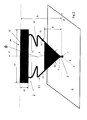
- the broadband monopole antenna in its flat designed basic version in Fig. 2 is essentially formed of a subband monopole 2 for covering the sub-band with a required antenna height 9 in combination with a top band monopole 1 with the top band monopole 8 with a common antenna connection point 3.
- a subband monopole 2 for covering the sub-band with a required antenna height 9 in combination with a top band monopole 1 with the top band monopole 8 with a common antenna connection point 3.
- To avoid an excessive effective antenna height 9 in the frequency range of the upper band of the lower band monopole 2 is designed in the frequency range of the upper band inductively high impedance conductor strips 15 with narrow stripline width 14 in conjunction with a roofing capacity 10.
- the latter is essentially embodied as a flat rectangular structure 16 and designed with a large horizontal extension 23 compared to the vertical extension 22.
- the monopole antenna according to the invention is made, for example, from an electrically conductive foil 33 (FIG. Fig. 16 ) designed as a contiguous, electrically conductive structure extending in a plane substantially perpendicular to the conductive base 6 level extending.
- an electrically conductive foil 33 (FIG. Fig. 16 ) designed as a contiguous, electrically conductive structure extending in a plane substantially perpendicular to the conductive base 6 level extending.
- the self-supporting, electrically conductive structure which is in particular integrally formed to use electrically conductive sheet or a self-supporting electrically conductive foil, resulting in the entire broadband monopole antenna 0 produce a mechanically self-supporting structure leaves.
- This structure can be exemplified by a punching operation or by a controlled cutting operation, for example produced by controlled laser cutting.
- a punching tool will prove to be economically advantageous in particularly large numbers, because the monopole antenna can be multiplied by automated punching operations extremely cost.
- the computer-controlled laser cutting can be more economical.
- Fabrication of the broadband monopole antenna 0 of sheet metal offers the particular advantage of metallic rigidity, which is of particular importance for use as a vehicle antenna.
- a particular advantage of this flat design structure is their negligible wind resistance to call, if it is designed to extend in an advantageous manner in a plane whose normal is oriented perpendicular to the direction of travel of the vehicle.
- the electrically conductive structure can be selected by the metallic coating of a dielectric plate, that is to say a printed circuit board.
- a dielectric plate that is to say a printed circuit board.
- the invention can be provided to print the structure of the broadband monopole antenna 0 on the circuit board in a known per se, but these for example, according to the contours of the broadband monopole antenna 0 with slight protrusion to keep the course of electric field lines in the lossy dielectric plate as small as possible.
- the trimming of the dielectric plate along the dot-dashed lines 34 is shown in FIG Fig. 16 shown. This form of representation is particularly advantageous in complicated geometric structure of the broadband monopole antenna 0, because the cutting lines 34 can be made less finely following the geometric structure and therefore require a less expensive punching tool.
- This value can in principle be achieved in an antenna according to the invention in its complete embodiment at the antenna connection point 3 with an antenna height 9 of 6 cm.
- the properties of the sub-band monopole 2 are essentially determined by its antenna height 9 and the size of the flat roof capacity 10, the horizontal extent 23 with about 6cm much larger, that is designed at least three times larger than the vertical extent 22. A much larger Although the vertical extent 22 increases the capacitance value of the roof capacitance 10, it reduces the effective height of the subband monopole 2, which, in contrast to the capacitance value, squares into the formation of the frequency bandwidth of the subband monopole 2.
- the formation of the upper band monopole 1 is essentially given by the flat triangular structure 4, provided that the inductive effect of the conductor strips 15 with narrow stripline width 14 for the separation of radio signals in the upper band of the roof capacity 10 is sufficiently large. This is usually given with a stripline width of less than or equal to 7 mm. To increase this separating effect can be inventively provided to provide the conductor strips 15 with meandering shapes 24.
- the functional division of the wideband monopole antenna 0 into the subband monopole 2 and the top band monopole 1 is not strictly seen. Rather, the transition between the effects is fluent and the subdivision is to be understood as a description of the main effects in the two frequency ranges.
- the mode of action of the upper band monopole 1 located above the conductive base surface 6 is essentially given by the design of the flat triangular structure 4.
- an apex triangular structure 4 with a triangular opening angle 12 is provided in this embodiment, the tip of which is connected to the antenna connection point 5.
- the antenna connection point 3 for the broadband monopole antenna 0 is formed.
- the height of the baseline of the flat triangular structure 4 above the conductive base 6 essentially forms the effective upper band monopole height 8, by which the frequency response of the upper band monopole 1 is substantially determined.
- the upper band monopole height 8 at the upper frequency limit of the upper band should not be greater than about 1/3 of the free space wavelength at this frequency.
- values between 30 and 90 degrees have proved favorable.
- the resulting wideband triangular structure allows it to meet the often-demanded impedance matching requirement at the VSWR ⁇ 2.5 in the upper band frequency range.
- a frame structure 11 is designed to achieve a particular rigidity.
- the electrically conductive structure consists of a material of particular rigidity, for example, thin sheet metal.
- the broadband monopole antenna 0 can be used with only one conductor strip 15, as in FIG Fig. 8 represented, designed. In the interest of mechanical stability for this, however, then to provide a larger stripline width 14. In order to design a sufficiently large inductive effect of the conductor strip 15, a plurality of meander-shaped expression 24 is generally necessary.
- a switching element with the operation of a parallel resonant circuit 28 in the conductor strips 15.
- This parallel resonant circuit is used to support the frequency-selective separation of the sub-band monopole 2 of signals in the upper band.
- the parallel resonant circuit 28 as in FIG Fig. 4
- a parallel capacitance 27 designed as an interdigital structure 26 and a parallel inductance 28 embodied as a strip conductor can also be included.
- This switching element can also be punched or cut from sheet metal into the design of the mechanically self-supporting broadband monopole antenna 0 via the conductor strips 15.
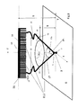
- the frequency bandwidth of the upper band monopole 1 is provided in an advantageous embodiment of the invention for this a three-dimensional structure, which is formed from the two-dimensional structure in such a way that instead of the flat triangular structure 4, an approximately conical structure is sought.
- the form of such a monopoly is in Fig. 9 indicated by the conical monopole 18 with electrically conductive lateral surfaces.
- the economically advantageous manufacturability of punched or cut sheet should be maintained.
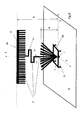
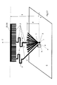
- the flat triangular structure 4 by in the lower triangular tip fan-like running together strip-shaped fins 20, as in Fig. 5 shown to execute.
- Fig. 10 By diffusing the slats 20 so that they lie on the lateral surface of a cone standing on the top, these become conical slats 30 and the conical monopole 18 in Fig. 9 is modeled in terms of its effect as a high band monopoly 1.
- Fig. 10 detailed represented and also according to the section AA 'in Fig. 11 seen as a plan view.
- Fig. 11 is the in Fig. 10 indicated cone cross section elliptical and thus the cone opening angle 17a ( Figure 10 ) in the x direction due to the requirements with respect to the aerodynamic properties of the antenna chosen smaller than the cone opening angle 17 in the direction of travel of the vehicle (y-direction).
- a ring-shaped satellite receiving antenna 25 is disposed concentrically with the antenna junction 3 of a broadband monopole antenna 0.
- the result in Fig. 6a illustrated azimuthal variations in the antenna gain of the satellite receiving antenna 25 at about 2.3 GHz.
- the design of the triangular structure 4 is made up of lamellae 20 that converge at the top in a fan-like manner, as in FIG Fig. 5 , more favorable than a closed flat triangular structure 4 according to Fig. 3 ,
- This advantage of slight influence on the radiation properties of the satellite receiving antenna 25 is particularly pronounced in the design of the upper band monopoly 1 of cone blades 30. This is an example of the in Fig.
- this according to the invention substantially vertically vertically separated from each other running, but at its upper end over a remaining strip 31 related strip-shaped roof blades 19, as in the Fig. 7 . 8th and 9 shown, executed.
- the strip width 21 should not be greater than 1/8 of the free space wavelength of the highest frequency in the upper band.
- FIG. Fig. 13 with view across the direction of travel (x-direction) and in Fig. 14 with view in direction of travel (y-direction) is shown.
- FIG. 14 visible extension of the cover 32 transversely to the direction of travel the possibility of further spatial design of the originally areal manufactured broadband monopole antenna 0 with the advantages of increasing the bandwidths of both monopolies 1 and 2.
- This is expressed by a better configurability of the antenna impedance with respect to the VSWR Value at the antenna connection point 3 off. This gives the possibility to be able to largely do without a matching network.
- the strip-shaped roof louvers 19 of the roofing capacity 10 which are connected at their upper end over a remaining strip, can be selected in such a way that they are arranged in the projection on a plane lying transversely to the direction of travel , These are alternately the in Fig. 13 black-filled marked roof slats 19a in the x direction and the white filled filled roof slats 19b deflected in the opposite direction in the negative x-direction, so that in the projection in Fig. 13 visible V-shaped structure is given.
- the capacity value of the roofing capacity 10 is greater. This leads to an increase in the bandwidth of the subband monopole 2 and facilitates compliance with the impedance matching condition at the VSWR value to be maintained.
- the lamellae 20, 20a, 20b about the inner boundary of the cover 32 following be understoodknelt following. That is, the strip-shaped fins 20, 20a, 20b of the upper band monopole 1 converging in the lower triangular tip become successively out of the plane of the triangular flat structure 4 in the manner bent, that they are arranged in the projection on a plane transverse to the direction of travel about V-shaped.
- the slats 20 are in such a way dignified that the in Fig. 13 fills 20 a marked in black in the x direction and the lamellae 20 b marked filled in white are deflected in opposite directions in the negative x direction, so that the fins projected in the projection in FIG Fig. 14 visible V-shaped structure is given.
- this measure serves to increase the frequency bandwidth of the upper band monopole 1 with the associated advantage in the realization of the impedance matching in the antenna base.
- antennas as in the Fig. 13 .
- the conductor strips can thus be shaped so that they extend as far as possible along the inner wall of the cover 32.
- the spatial design according to the invention starting from the described two-dimensional design of the monopole antenna 0 according to the invention, is additionally advantageous with respect to the problem of impedance matching over large frequency ranges.
- the special advantage associated with the present invention is that this spatially designed antenna can be punched or cut from a sheet-like electrically conductive structure (sheet or foil) and designed by simple subsequent bending as described above.
- two broadband monopole antennas 0 and 0a according to the invention under a cover 32 in the direction of travel behind each other, as in Fig. 15 to install. It has been found that the annular satellite antennas 25 at the base of a broadband monopole antenna 0 by the presence of other broadband monopole antenna 0a undergoes no disturbing influence on their radiation properties. Conversely, this also applies with regard to the effect of the broadband monopole antenna 0 on the satellite antennas 25a at the base of the broadband monopole antenna 0a.
- a broadband monopole antenna 0 in a further advantageous application of a broadband monopole antenna 0 according to the invention, this is supplemented by a further, same to this same broadband monopole antenna in a known per se to a dipole.
- the mirror image of the broadband monopole antenna 0 is replaced at the conductive base 6 with their omission by this further broadband monopole antenna in such a way that a symmetrical to the plane of the conductive surface 6 dipole is given.
- the symmetrical antenna connection point of this dipole is formed between the antenna connection point 5 of the broadband monopole antenna 0 and the antenna connection point 5 which is mirrored to the conductive base 6.
- a broadband monopole antenna 0 is in support of the impedance matching at the lower frequency end of the lower band connected at its upper end with the roof capacity 10 and the conductive base 6 extending towards coupling ladder 35 is present, which at its lower end with the conductive base 6 is coupled.
- This coupling conductor 35 is in Fig. 17 illustrates and supplements the subband monopole 2 in such a way that it is possible to improve the impedance matching at the antenna connection point 3, at the lower frequency end of the subband.
- the coupling conductor width 37 or by partially meandering expression 24 of the coupling conductor 35 its inductive effect can be suitably adjusted to the requirements for the impedance matching (eg VSWR ⁇ 3). With sufficient inductively high-impedance design of the Koppleiters 35 this is ineffective in the frequency range of the upper band monopoly 1 in such a way that its radiation properties are not affected.
- the impedance matching can be further improved in that this coupling of the coupling conductor 35 with the conductive base 6 via a two-pole coupling network 36, consisting of reactive elements occurs.
Landscapes
- Engineering & Computer Science (AREA)
- Remote Sensing (AREA)
- Details Of Aerials (AREA)
- Waveguide Aerials (AREA)
- Variable-Direction Aerials And Aerial Arrays (AREA)
Applications Claiming Priority (1)
| Application Number | Priority Date | Filing Date | Title |
|---|---|---|---|
| DE102013005001.4A DE102013005001A1 (de) | 2013-03-24 | 2013-03-24 | Breitband-Monopolantenne für zwei durch eine Frequenzlücke getrennte Frequenzbänder im Dezimeterwellenbereich für Fahrzeuge |
Publications (3)
| Publication Number | Publication Date |
|---|---|
| EP2784874A2 true EP2784874A2 (fr) | 2014-10-01 |
| EP2784874A3 EP2784874A3 (fr) | 2014-12-03 |
| EP2784874B1 EP2784874B1 (fr) | 2016-07-20 |
Family
ID=50276966
Family Applications (1)
| Application Number | Title | Priority Date | Filing Date |
|---|---|---|---|
| EP14159092.7A Active EP2784874B1 (fr) | 2013-03-24 | 2014-03-12 | Antenne monopôle à large bande pour deux bandes de fréquences séparées par un écart de fréquence dans la plage d'ondes décimétriques pour des véhicules |
Country Status (3)
| Country | Link |
|---|---|
| US (1) | US20140285387A1 (fr) |
| EP (1) | EP2784874B1 (fr) |
| DE (1) | DE102013005001A1 (fr) |
Cited By (4)
| Publication number | Priority date | Publication date | Assignee | Title |
|---|---|---|---|---|
| CN104810611A (zh) * | 2015-04-28 | 2015-07-29 | 邝嘉豪 | 设有第一矩形过孔的单极性天线 |
| CN104810610A (zh) * | 2015-04-28 | 2015-07-29 | 邝嘉豪 | 设有隔离带的双极性振子 |
| CN104882665A (zh) * | 2015-04-28 | 2015-09-02 | 邝嘉豪 | 一种高增益具有第二辐射片的单极性振子 |
| DE102022001407A1 (de) | 2022-04-25 | 2023-10-26 | Heinz Lindenmeier | Kombinationsantenne für Mobilfunk und Satellitenempfang |
Families Citing this family (10)
| Publication number | Priority date | Publication date | Assignee | Title |
|---|---|---|---|---|
| FR3025611B1 (fr) * | 2014-09-05 | 2019-04-19 | Centre National D'etudes Spatiales | Procede d'authentification de signaux recus d'une constellation de satellites |
| DE102016010200A1 (de) * | 2016-05-04 | 2017-11-09 | Heinz Lindenmeier | Antenne unter einer schalenförmigen Antennenschutzhaube für Fahrzeuge |
| DE102016005556A1 (de) | 2016-05-06 | 2017-11-09 | Heinz Lindenmeier | Satellitenempfangsantenne unter einer Antennenschutzhaube |
| CN110034400A (zh) | 2018-01-05 | 2019-07-19 | 台达电子工业股份有限公司 | 天线装置和天线系统 |
| CN211295369U (zh) * | 2018-09-28 | 2020-08-18 | 株式会社友华 | 车载天线装置 |
| WO2020240916A1 (fr) * | 2019-05-29 | 2020-12-03 | パナソニックIpマネジメント株式会社 | Antenne multibande |
| CN113109757A (zh) * | 2021-04-21 | 2021-07-13 | 广东圣大电子有限公司 | 一种基于干涉仪的测向微波信道组件 |
| JP7836247B2 (ja) * | 2021-08-26 | 2026-03-26 | セントラル硝子プロダクツ株式会社 | アンテナ装置及び窓ガラス |
| CN114899593B (zh) * | 2022-05-25 | 2024-09-20 | 陕西北斗科技开发应用有限公司 | 一款适用于北斗与wlan系统互补结构加载微带天线 |
| US12322884B2 (en) * | 2023-04-12 | 2025-06-03 | Raytheon Company | Nested wire monopole HF antenna |
Family Cites Families (20)
| Publication number | Priority date | Publication date | Assignee | Title |
|---|---|---|---|---|
| FR2634068B1 (fr) * | 1988-07-08 | 1990-09-14 | Thomson Csf | Antenne de reception a large bande |
| JPH10513329A (ja) * | 1995-02-06 | 1998-12-15 | メガウエイブ コーポレーション | 窓ガラスアンテナ |
| US5872546A (en) * | 1995-09-27 | 1999-02-16 | Ntt Mobile Communications Network Inc. | Broadband antenna using a semicircular radiator |
| JP3213564B2 (ja) | 1997-02-26 | 2001-10-02 | 日本アンテナ株式会社 | 多共振アンテナ |
| EP1223637B1 (fr) * | 1999-09-20 | 2005-03-30 | Fractus, S.A. | Antennes multiniveau |
| WO2002001668A2 (fr) * | 2000-06-28 | 2002-01-03 | The Penn State Research Foundation | Antennes fractales bande large conformees miniatures sur substrats a constante dielectrique elevee et sur couches chirales |
| US6693600B1 (en) * | 2000-11-24 | 2004-02-17 | Paul G. Elliot | Ultra-broadband antenna achieved by combining a monocone with other antennas |
| US6677915B1 (en) * | 2001-02-12 | 2004-01-13 | Ethertronics, Inc. | Shielded spiral sheet antenna structure and method |
| US6567053B1 (en) * | 2001-02-12 | 2003-05-20 | Eli Yablonovitch | Magnetic dipole antenna structure and method |
| US6486849B2 (en) * | 2001-02-14 | 2002-11-26 | Raytheon Company | Small L-band antenna |
| CN100382385C (zh) * | 2001-10-16 | 2008-04-16 | 弗拉克托斯股份有限公司 | 加载天线 |
| US9755314B2 (en) * | 2001-10-16 | 2017-09-05 | Fractus S.A. | Loaded antenna |
| US6917341B2 (en) * | 2002-06-11 | 2005-07-12 | Matsushita Electric Industrial Co., Ltd. | Top-loading monopole antenna apparatus with short-circuit conductor connected between top-loading electrode and grounding conductor |
| JP2005057438A (ja) * | 2003-08-01 | 2005-03-03 | Sony Corp | アンテナ装置 |
| US7245263B2 (en) * | 2005-02-18 | 2007-07-17 | Ricoh Company, Ltd. | Antenna |
| US7248223B2 (en) * | 2005-12-05 | 2007-07-24 | Elta Systems Ltd | Fractal monopole antenna |
| US7973731B2 (en) * | 2008-05-23 | 2011-07-05 | Harris Corporation | Folded conical antenna and associated methods |
| JP2010021856A (ja) * | 2008-07-11 | 2010-01-28 | Nippon Antenna Co Ltd | アンテナ装置 |
| KR101192298B1 (ko) * | 2011-01-25 | 2012-10-17 | 인팩일렉스 주식회사 | 샤크핀 통합형 안테나 |
| DE102012003460A1 (de) * | 2011-03-15 | 2012-09-20 | Heinz Lindenmeier | Multiband-Empfangsantenne für den kombinierten Empfang von Satellitensignalen und terrestrisch ausgestrahlten Rundfunksignalen |
-
2013
- 2013-03-24 DE DE102013005001.4A patent/DE102013005001A1/de not_active Withdrawn
-
2014
- 2014-03-12 EP EP14159092.7A patent/EP2784874B1/fr active Active
- 2014-03-21 US US14/221,669 patent/US20140285387A1/en not_active Abandoned
Non-Patent Citations (1)
| Title |
|---|
| None |
Cited By (6)
| Publication number | Priority date | Publication date | Assignee | Title |
|---|---|---|---|---|
| CN104810611A (zh) * | 2015-04-28 | 2015-07-29 | 邝嘉豪 | 设有第一矩形过孔的单极性天线 |
| CN104810610A (zh) * | 2015-04-28 | 2015-07-29 | 邝嘉豪 | 设有隔离带的双极性振子 |
| CN104882665A (zh) * | 2015-04-28 | 2015-09-02 | 邝嘉豪 | 一种高增益具有第二辐射片的单极性振子 |
| DE102022001407A1 (de) | 2022-04-25 | 2023-10-26 | Heinz Lindenmeier | Kombinationsantenne für Mobilfunk und Satellitenempfang |
| EP4270647A1 (fr) | 2022-04-25 | 2023-11-01 | Fuba Automotive Electronics GmbH | Antenne combinée pour la réception radio mobile et satellite |
| US12278432B2 (en) | 2022-04-25 | 2025-04-15 | Fuba Automotive Electronics Gmbh | Combination antenna for mobile communications and satellite reception |
Also Published As
| Publication number | Publication date |
|---|---|
| DE102013005001A1 (de) | 2014-09-25 |
| EP2784874A3 (fr) | 2014-12-03 |
| EP2784874B1 (fr) | 2016-07-20 |
| US20140285387A1 (en) | 2014-09-25 |
Similar Documents
| Publication | Publication Date | Title |
|---|---|---|
| EP2784874B1 (fr) | Antenne monopôle à large bande pour deux bandes de fréquences séparées par un écart de fréquence dans la plage d'ondes décimétriques pour des véhicules | |
| EP3178129B1 (fr) | Antenne unipolaire à bande large à structure multiple pour deux bandes de fréquence séparées par un espace blanc dans la plage d'ondes décimétriques, destinée à des véhicules | |
| EP0841715B1 (fr) | Antenne plate | |
| DE102012003460A1 (de) | Multiband-Empfangsantenne für den kombinierten Empfang von Satellitensignalen und terrestrisch ausgestrahlten Rundfunksignalen | |
| EP2693565B1 (fr) | Emetteur électrique pour signaux radio polarisés verticalement | |
| DE102016204868B4 (de) | Antennenvorrichtung | |
| EP1344277A1 (fr) | Antenne, en particulier antenne radio mobile | |
| DE102016011890A1 (de) | Mobilfunk-Antenne | |
| DE29925006U1 (de) | Mehrebenenantenne | |
| EP3474374B1 (fr) | Dispositif d'antenne pour signaux satellites polarisés circulairement sur un véhicule | |
| DE69925985T2 (de) | Antenne | |
| DE112013002000T5 (de) | Antennenvorrichtung | |
| EP3734755B1 (fr) | Antenne combinée pour services de communication mobiles pour véhicules | |
| DE102014115054A1 (de) | Gedruckte Dualband-Monopolantenne | |
| WO2002001674A1 (fr) | Antenne fendue | |
| DE102013201222A1 (de) | Antennenvorrichtung | |
| DE102006006144A1 (de) | Dipolantenne | |
| WO2007048258A1 (fr) | Configuration d’antenne avec antenne monopole large bande | |
| EP4270647B1 (fr) | Antenne combinée pour radio mobile et la réception satellite | |
| DE102018116631A1 (de) | Spiralantennensystem | |
| EP2756550B1 (fr) | Antenne multibande pour véhicule automobile | |
| DE102005018531B4 (de) | Gefaltete Monopolantenne | |
| DE102018008276A1 (de) | Antenne | |
| DE102007061740A1 (de) | Mehrbereichsantenne sowie Verfahren | |
| DE102016005556A1 (de) | Satellitenempfangsantenne unter einer Antennenschutzhaube |
Legal Events
| Date | Code | Title | Description |
|---|---|---|---|
| 17P | Request for examination filed |
Effective date: 20140312 |
|
| AK | Designated contracting states |
Kind code of ref document: A2 Designated state(s): AL AT BE BG CH CY CZ DE DK EE ES FI FR GB GR HR HU IE IS IT LI LT LU LV MC MK MT NL NO PL PT RO RS SE SI SK SM TR |
|
| AX | Request for extension of the european patent |
Extension state: BA ME |
|
| PUAI | Public reference made under article 153(3) epc to a published international application that has entered the european phase |
Free format text: ORIGINAL CODE: 0009012 |
|
| PUAL | Search report despatched |
Free format text: ORIGINAL CODE: 0009013 |
|
| AK | Designated contracting states |
Kind code of ref document: A3 Designated state(s): AL AT BE BG CH CY CZ DE DK EE ES FI FR GB GR HR HU IE IS IT LI LT LU LV MC MK MT NL NO PL PT RO RS SE SI SK SM TR |
|
| AX | Request for extension of the european patent |
Extension state: BA ME |
|
| RIC1 | Information provided on ipc code assigned before grant |
Ipc: H01Q 5/00 20060101ALI20141028BHEP Ipc: H01Q 9/36 20060101ALI20141028BHEP Ipc: H01Q 1/32 20060101AFI20141028BHEP Ipc: H01Q 9/40 20060101ALI20141028BHEP |
|
| R17P | Request for examination filed (corrected) |
Effective date: 20150602 |
|
| RBV | Designated contracting states (corrected) |
Designated state(s): AL AT BE BG CH CY CZ DE DK EE ES FI FR GB GR HR HU IE IS IT LI LT LU LV MC MK MT NL NO PL PT RO RS SE SI SK SM TR |
|
| GRAP | Despatch of communication of intention to grant a patent |
Free format text: ORIGINAL CODE: EPIDOSNIGR1 |
|
| INTG | Intention to grant announced |
Effective date: 20160128 |
|
| GRAS | Grant fee paid |
Free format text: ORIGINAL CODE: EPIDOSNIGR3 |
|
| GRAA | (expected) grant |
Free format text: ORIGINAL CODE: 0009210 |
|
| AK | Designated contracting states |
Kind code of ref document: B1 Designated state(s): AL AT BE BG CH CY CZ DE DK EE ES FI FR GB GR HR HU IE IS IT LI LT LU LV MC MK MT NL NO PL PT RO RS SE SI SK SM TR |
|
| REG | Reference to a national code |
Ref country code: GB Ref legal event code: FG4D Free format text: NOT ENGLISH |
|
| REG | Reference to a national code |
Ref country code: CH Ref legal event code: EP |
|
| REG | Reference to a national code |
Ref country code: IE Ref legal event code: FG4D Free format text: LANGUAGE OF EP DOCUMENT: GERMAN |
|
| REG | Reference to a national code |
Ref country code: AT Ref legal event code: REF Ref document number: 814739 Country of ref document: AT Kind code of ref document: T Effective date: 20160815 |
|
| REG | Reference to a national code |
Ref country code: DE Ref legal event code: R096 Ref document number: 502014001130 Country of ref document: DE |
|
| REG | Reference to a national code |
Ref country code: LT Ref legal event code: MG4D |
|
| REG | Reference to a national code |
Ref country code: NL Ref legal event code: MP Effective date: 20160720 |
|
| PG25 | Lapsed in a contracting state [announced via postgrant information from national office to epo] |
Ref country code: IS Free format text: LAPSE BECAUSE OF FAILURE TO SUBMIT A TRANSLATION OF THE DESCRIPTION OR TO PAY THE FEE WITHIN THE PRESCRIBED TIME-LIMIT Effective date: 20161120 Ref country code: HR Free format text: LAPSE BECAUSE OF FAILURE TO SUBMIT A TRANSLATION OF THE DESCRIPTION OR TO PAY THE FEE WITHIN THE PRESCRIBED TIME-LIMIT Effective date: 20160720 Ref country code: LT Free format text: LAPSE BECAUSE OF FAILURE TO SUBMIT A TRANSLATION OF THE DESCRIPTION OR TO PAY THE FEE WITHIN THE PRESCRIBED TIME-LIMIT Effective date: 20160720 Ref country code: FI Free format text: LAPSE BECAUSE OF FAILURE TO SUBMIT A TRANSLATION OF THE DESCRIPTION OR TO PAY THE FEE WITHIN THE PRESCRIBED TIME-LIMIT Effective date: 20160720 Ref country code: NO Free format text: LAPSE BECAUSE OF FAILURE TO SUBMIT A TRANSLATION OF THE DESCRIPTION OR TO PAY THE FEE WITHIN THE PRESCRIBED TIME-LIMIT Effective date: 20161020 Ref country code: RS Free format text: LAPSE BECAUSE OF FAILURE TO SUBMIT A TRANSLATION OF THE DESCRIPTION OR TO PAY THE FEE WITHIN THE PRESCRIBED TIME-LIMIT Effective date: 20160720 Ref country code: NL Free format text: LAPSE BECAUSE OF FAILURE TO SUBMIT A TRANSLATION OF THE DESCRIPTION OR TO PAY THE FEE WITHIN THE PRESCRIBED TIME-LIMIT Effective date: 20160720 |
|
| PG25 | Lapsed in a contracting state [announced via postgrant information from national office to epo] |
Ref country code: GR Free format text: LAPSE BECAUSE OF FAILURE TO SUBMIT A TRANSLATION OF THE DESCRIPTION OR TO PAY THE FEE WITHIN THE PRESCRIBED TIME-LIMIT Effective date: 20161021 Ref country code: LV Free format text: LAPSE BECAUSE OF FAILURE TO SUBMIT A TRANSLATION OF THE DESCRIPTION OR TO PAY THE FEE WITHIN THE PRESCRIBED TIME-LIMIT Effective date: 20160720 Ref country code: PT Free format text: LAPSE BECAUSE OF FAILURE TO SUBMIT A TRANSLATION OF THE DESCRIPTION OR TO PAY THE FEE WITHIN THE PRESCRIBED TIME-LIMIT Effective date: 20161121 Ref country code: SE Free format text: LAPSE BECAUSE OF FAILURE TO SUBMIT A TRANSLATION OF THE DESCRIPTION OR TO PAY THE FEE WITHIN THE PRESCRIBED TIME-LIMIT Effective date: 20160720 Ref country code: ES Free format text: LAPSE BECAUSE OF FAILURE TO SUBMIT A TRANSLATION OF THE DESCRIPTION OR TO PAY THE FEE WITHIN THE PRESCRIBED TIME-LIMIT Effective date: 20160720 Ref country code: PL Free format text: LAPSE BECAUSE OF FAILURE TO SUBMIT A TRANSLATION OF THE DESCRIPTION OR TO PAY THE FEE WITHIN THE PRESCRIBED TIME-LIMIT Effective date: 20160720 |
|
| REG | Reference to a national code |
Ref country code: FR Ref legal event code: PLFP Year of fee payment: 4 |
|
| REG | Reference to a national code |
Ref country code: DE Ref legal event code: R097 Ref document number: 502014001130 Country of ref document: DE |
|
| PG25 | Lapsed in a contracting state [announced via postgrant information from national office to epo] |
Ref country code: RO Free format text: LAPSE BECAUSE OF FAILURE TO SUBMIT A TRANSLATION OF THE DESCRIPTION OR TO PAY THE FEE WITHIN THE PRESCRIBED TIME-LIMIT Effective date: 20160720 Ref country code: EE Free format text: LAPSE BECAUSE OF FAILURE TO SUBMIT A TRANSLATION OF THE DESCRIPTION OR TO PAY THE FEE WITHIN THE PRESCRIBED TIME-LIMIT Effective date: 20160720 |
|
| PLBE | No opposition filed within time limit |
Free format text: ORIGINAL CODE: 0009261 |
|
| STAA | Information on the status of an ep patent application or granted ep patent |
Free format text: STATUS: NO OPPOSITION FILED WITHIN TIME LIMIT |
|
| PG25 | Lapsed in a contracting state [announced via postgrant information from national office to epo] |
Ref country code: CZ Free format text: LAPSE BECAUSE OF FAILURE TO SUBMIT A TRANSLATION OF THE DESCRIPTION OR TO PAY THE FEE WITHIN THE PRESCRIBED TIME-LIMIT Effective date: 20160720 Ref country code: DK Free format text: LAPSE BECAUSE OF FAILURE TO SUBMIT A TRANSLATION OF THE DESCRIPTION OR TO PAY THE FEE WITHIN THE PRESCRIBED TIME-LIMIT Effective date: 20160720 Ref country code: SK Free format text: LAPSE BECAUSE OF FAILURE TO SUBMIT A TRANSLATION OF THE DESCRIPTION OR TO PAY THE FEE WITHIN THE PRESCRIBED TIME-LIMIT Effective date: 20160720 Ref country code: SM Free format text: LAPSE BECAUSE OF FAILURE TO SUBMIT A TRANSLATION OF THE DESCRIPTION OR TO PAY THE FEE WITHIN THE PRESCRIBED TIME-LIMIT Effective date: 20160720 Ref country code: BG Free format text: LAPSE BECAUSE OF FAILURE TO SUBMIT A TRANSLATION OF THE DESCRIPTION OR TO PAY THE FEE WITHIN THE PRESCRIBED TIME-LIMIT Effective date: 20161020 |
|
| 26N | No opposition filed |
Effective date: 20170421 |
|
| PG25 | Lapsed in a contracting state [announced via postgrant information from national office to epo] |
Ref country code: SI Free format text: LAPSE BECAUSE OF FAILURE TO SUBMIT A TRANSLATION OF THE DESCRIPTION OR TO PAY THE FEE WITHIN THE PRESCRIBED TIME-LIMIT Effective date: 20160720 |
|
| REG | Reference to a national code |
Ref country code: CH Ref legal event code: PL |
|
| PG25 | Lapsed in a contracting state [announced via postgrant information from national office to epo] |
Ref country code: MC Free format text: LAPSE BECAUSE OF FAILURE TO SUBMIT A TRANSLATION OF THE DESCRIPTION OR TO PAY THE FEE WITHIN THE PRESCRIBED TIME-LIMIT Effective date: 20160720 |
|
| REG | Reference to a national code |
Ref country code: IE Ref legal event code: MM4A |
|
| PG25 | Lapsed in a contracting state [announced via postgrant information from national office to epo] |
Ref country code: LU Free format text: LAPSE BECAUSE OF NON-PAYMENT OF DUE FEES Effective date: 20170312 |
|
| PG25 | Lapsed in a contracting state [announced via postgrant information from national office to epo] |
Ref country code: LI Free format text: LAPSE BECAUSE OF NON-PAYMENT OF DUE FEES Effective date: 20170331 Ref country code: CH Free format text: LAPSE BECAUSE OF NON-PAYMENT OF DUE FEES Effective date: 20170331 Ref country code: IE Free format text: LAPSE BECAUSE OF NON-PAYMENT OF DUE FEES Effective date: 20170312 |
|
| REG | Reference to a national code |
Ref country code: BE Ref legal event code: MM Effective date: 20170331 |
|
| REG | Reference to a national code |
Ref country code: FR Ref legal event code: PLFP Year of fee payment: 5 |
|
| PG25 | Lapsed in a contracting state [announced via postgrant information from national office to epo] |
Ref country code: BE Free format text: LAPSE BECAUSE OF NON-PAYMENT OF DUE FEES Effective date: 20170331 |
|
| PG25 | Lapsed in a contracting state [announced via postgrant information from national office to epo] |
Ref country code: MT Free format text: LAPSE BECAUSE OF FAILURE TO SUBMIT A TRANSLATION OF THE DESCRIPTION OR TO PAY THE FEE WITHIN THE PRESCRIBED TIME-LIMIT Effective date: 20160720 |
|
| PG25 | Lapsed in a contracting state [announced via postgrant information from national office to epo] |
Ref country code: AL Free format text: LAPSE BECAUSE OF FAILURE TO SUBMIT A TRANSLATION OF THE DESCRIPTION OR TO PAY THE FEE WITHIN THE PRESCRIBED TIME-LIMIT Effective date: 20160720 |
|
| PG25 | Lapsed in a contracting state [announced via postgrant information from national office to epo] |
Ref country code: HU Free format text: LAPSE BECAUSE OF FAILURE TO SUBMIT A TRANSLATION OF THE DESCRIPTION OR TO PAY THE FEE WITHIN THE PRESCRIBED TIME-LIMIT; INVALID AB INITIO Effective date: 20140312 |
|
| PG25 | Lapsed in a contracting state [announced via postgrant information from national office to epo] |
Ref country code: CY Free format text: LAPSE BECAUSE OF FAILURE TO SUBMIT A TRANSLATION OF THE DESCRIPTION OR TO PAY THE FEE WITHIN THE PRESCRIBED TIME-LIMIT Effective date: 20160720 |
|
| PG25 | Lapsed in a contracting state [announced via postgrant information from national office to epo] |
Ref country code: MK Free format text: LAPSE BECAUSE OF FAILURE TO SUBMIT A TRANSLATION OF THE DESCRIPTION OR TO PAY THE FEE WITHIN THE PRESCRIBED TIME-LIMIT Effective date: 20160720 |
|
| PG25 | Lapsed in a contracting state [announced via postgrant information from national office to epo] |
Ref country code: TR Free format text: LAPSE BECAUSE OF FAILURE TO SUBMIT A TRANSLATION OF THE DESCRIPTION OR TO PAY THE FEE WITHIN THE PRESCRIBED TIME-LIMIT Effective date: 20160720 |
|
| PGFP | Annual fee paid to national office [announced via postgrant information from national office to epo] |
Ref country code: GB Payment date: 20200323 Year of fee payment: 7 |
|
| REG | Reference to a national code |
Ref country code: AT Ref legal event code: MM01 Ref document number: 814739 Country of ref document: AT Kind code of ref document: T Effective date: 20190312 |
|
| PG25 | Lapsed in a contracting state [announced via postgrant information from national office to epo] |
Ref country code: AT Free format text: LAPSE BECAUSE OF NON-PAYMENT OF DUE FEES Effective date: 20190312 |
|
| GBPC | Gb: european patent ceased through non-payment of renewal fee |
Effective date: 20210312 |
|
| PG25 | Lapsed in a contracting state [announced via postgrant information from national office to epo] |
Ref country code: GB Free format text: LAPSE BECAUSE OF NON-PAYMENT OF DUE FEES Effective date: 20210312 |
|
| PGFP | Annual fee paid to national office [announced via postgrant information from national office to epo] |
Ref country code: FR Payment date: 20230324 Year of fee payment: 10 |
|
| PGFP | Annual fee paid to national office [announced via postgrant information from national office to epo] |
Ref country code: IT Payment date: 20230328 Year of fee payment: 10 |
|
| PG25 | Lapsed in a contracting state [announced via postgrant information from national office to epo] |
Ref country code: FR Free format text: LAPSE BECAUSE OF NON-PAYMENT OF DUE FEES Effective date: 20240331 |
|
| PG25 | Lapsed in a contracting state [announced via postgrant information from national office to epo] |
Ref country code: FR Free format text: LAPSE BECAUSE OF NON-PAYMENT OF DUE FEES Effective date: 20240331 |
|
| PG25 | Lapsed in a contracting state [announced via postgrant information from national office to epo] |
Ref country code: IT Free format text: LAPSE BECAUSE OF NON-PAYMENT OF DUE FEES Effective date: 20240312 |
|
| PGFP | Annual fee paid to national office [announced via postgrant information from national office to epo] |
Ref country code: DE Payment date: 20250527 Year of fee payment: 12 |