EP2784894A1 - Störsignalschutz in einem Leistungssteuerungssystem - Google Patents
Störsignalschutz in einem Leistungssteuerungssystem Download PDFInfo
- Publication number
- EP2784894A1 EP2784894A1 EP20130161586 EP13161586A EP2784894A1 EP 2784894 A1 EP2784894 A1 EP 2784894A1 EP 20130161586 EP20130161586 EP 20130161586 EP 13161586 A EP13161586 A EP 13161586A EP 2784894 A1 EP2784894 A1 EP 2784894A1
- Authority
- EP
- European Patent Office
- Prior art keywords
- magnetisation
- switching
- load
- alternating current
- control
- Prior art date
- Legal status (The legal status is an assumption and is not a legal conclusion. Google has not performed a legal analysis and makes no representation as to the accuracy of the status listed.)
- Withdrawn
Links
Images


Classifications
-
- H—ELECTRICITY
- H02—GENERATION; CONVERSION OR DISTRIBUTION OF ELECTRIC POWER
- H02H—EMERGENCY PROTECTIVE CIRCUIT ARRANGEMENTS
- H02H9/00—Emergency protective circuit arrangements for limiting excess current or voltage without disconnection
- H02H9/001—Emergency protective circuit arrangements for limiting excess current or voltage without disconnection limiting speed of change of electric quantities, e.g. soft switching on or off
- H02H9/002—Emergency protective circuit arrangements for limiting excess current or voltage without disconnection limiting speed of change of electric quantities, e.g. soft switching on or off limiting inrush current on switching on of inductive loads subjected to remanence, e.g. transformers
-
- H—ELECTRICITY
- H04—ELECTRIC COMMUNICATION TECHNIQUE
- H04B—TRANSMISSION
- H04B3/00—Line transmission systems
- H04B3/54—Systems for transmission via power distribution lines
Definitions
- This invention relates to protecting against transients and inrush currents in a power control system, for example in a subsea fluid production well power control system.
- the present invention removes the need for a separate DC power supply to achieve the same pre-magnetisation.
- a system for providing alternating current to at least one inductive load including at least one switching means for switching power to said at least one load on and off, control means adapted for controlling said at least one switching means and a pre-magnetisation means, wherein the pre-magnetisation means is configured to generate pulses which cause the switching means to pre-magnetise the inductive load.
- a method for providing alternating current to at least one inductive load comprising the steps of:
- the control means could comprise a zero voltage crossing comparator and phase control logic, and the output of said comparator could be used by the phase control logic to control the switching means to switch power to said at least one load on and off in phase with an input alternating current at a positive going crossing point of the alternating current waveform.
- the pre-magnetisation means could comprise a pre-magnetisation pulse generator.
- the pre-magnetisation means could comprise pre-magnetisation control logic configured to control the pre-magnetisation pulse generator to generate a train of pulses, wherein each pulse controls the switching means to switch power to said at least one load on prior to a negative going crossing point of the alternating current waveform.
- the alternating current waveform could comprise a sine wave.
- the at least one inductive load could comprise a winding of a transformer.
- a system according to the invention typically comprises a power control system for a subsea well and a method according to the invention typically is performed in such a system.
- Fig. 1 shows a typical electronic power control system which employs a SCR power switch as the semiconductor switching device.
- the load is a subsea electronics module (SEM) which is part of a subsea fluid (e.g. hydrocarbon) production well control system.
- SEM subsea electronics module
- the present invention may be applied to any transformer fed system.
- the power control system 1 conventionally consists of a zero voltage crossing comparator 2, feeding phase control logic 3, which ensures that, under controlled conditions the switching on and off of a SCR power switch 4 occurs when the AC supply voltage is at the zero voltage crossing point.
- the switched power from the SCR power switch 4 feeds a transformer 5, the output of which feeds an AC to DC converter 6, which in turn supplies power to a DC load 7 (in this case, a SEM).
- the embodiment of the present invention is a modification to this arrangement, specifically including the addition of transformer pre-magnetisation logic 8, controlling a pulse generator 9, which produces pre-magnetisation DC power generation by the SCR power switch 4 to the transformer 5.
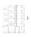
- Fig. 2 illustrates switching on of the supply to the transformer 5 after the transformer has been switched off with a significant magnetic remanance in its core with the phase control logic 3 and the pre-magnetisation control logic 8 disabled, such that the SCR power switch 4 is switched on at the positive going zero crossing point of the input sine waveform.
- channel 1 the input voltage rises but soon results in transformer core saturation, which results in a very large inrush current (see channel 4) which further results in serious distortion of the input supply voltage waveform and consequential voltage transients which can damage the supply load.
- the effect can also be seen to persist over several cycles of the supply voltage.
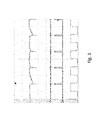
- Fig. 3 illustrates the operation of the pre-magnetisation modification of the SCR power switch 4 control circuitry, in accordance with the embodiment of the present invention.
- the AC supply causes the pre-magnetisation logic 8 to instruct the pre-magnetisation pulse generator 9 output a train of short duration SCR switching on pulses (see channel 3) to turn on the SCR power switch 4 just before the previous input voltage negative half sine wave reaches the zero voltage crossing point, which results in the SCR power switch 4 switching off. Note that this occurs on the negative half sine wave only.
- the correct switching on point is triggered by the pre-magnetisation logic 8 from the zero crossing point detector 2 (see channel 2).
- This train of short SCR switching on pulses on the negative half sine wave cycles only results in a small negative DC supply voltage being applied to the transformer, which ensures that the remanance in its core is small and slightly negative relative to the next turn on cycle, i.e. set to prevent transformer core saturation when the next positive sine wave supply voltage is applied at switching on.
- the train of pre-magnetisation pulses is switched off after a few cycles, whereupon the phased controlled switching on process by phase control logic 3 is allowed to initiate the switching on cycle.
- Fig. 4 shows the resultant oscilloscope trace of the four channels referred to previously when pre-magnetisation has been applied prior to the phase controlled switching on process.
- the input current surge on channel 4 and the input supply waveform distortion on channel 1 are drastically reduced compared to Fig. 2 .
- These traces were recorded after the transformer 5 had been deliberately set to have a high core remanance and connected to the system.
- Transformers supplying the electronics of subsea fluid extraction wells must be relied upon not to be the source of damaging voltage transients as they are located subsea, often beneath many kilometres of sea water. Consequently, they are very expensive to recover and repair.
- the present invention enables a substantial reduction of the risk of such damaging transients and thus potentially saves well operators major operating costs.
Landscapes
- Engineering & Computer Science (AREA)
- Power Engineering (AREA)
- Computer Networks & Wireless Communication (AREA)
- Signal Processing (AREA)
- Protection Of Transformers (AREA)
- Control Of Electrical Variables (AREA)
- Keying Circuit Devices (AREA)
- Direct Current Feeding And Distribution (AREA)
- Dc-Dc Converters (AREA)
Priority Applications (8)
| Application Number | Priority Date | Filing Date | Title |
|---|---|---|---|
| EP20130161586 EP2784894A1 (de) | 2013-03-28 | 2013-03-28 | Störsignalschutz in einem Leistungssteuerungssystem |
| AU2014201699A AU2014201699B9 (en) | 2013-03-28 | 2014-03-21 | Protecting against transients in a power control system |
| SG10201707961XA SG10201707961XA (en) | 2013-03-28 | 2014-03-24 | Protecting against transients in a power control system |
| SG10201400906RA SG10201400906RA (en) | 2013-03-28 | 2014-03-24 | Protecting against transients in a power control system |
| US14/227,199 US20140293488A1 (en) | 2013-03-28 | 2014-03-27 | Protecting against transients in a power control system |
| BR102014007390A BR102014007390A2 (pt) | 2013-03-28 | 2014-03-27 | sistema e método para fornecer corrente alternada |
| CN201410121535.4A CN104078917A (zh) | 2013-03-28 | 2014-03-28 | 功率控制系统中对瞬变的防护 |
| US16/440,649 US20210296886A1 (en) | 2013-03-28 | 2019-06-13 | Protecting against transients in a power control system |
Applications Claiming Priority (1)
| Application Number | Priority Date | Filing Date | Title |
|---|---|---|---|
| EP20130161586 EP2784894A1 (de) | 2013-03-28 | 2013-03-28 | Störsignalschutz in einem Leistungssteuerungssystem |
Publications (1)
| Publication Number | Publication Date |
|---|---|
| EP2784894A1 true EP2784894A1 (de) | 2014-10-01 |
Family
ID=48049793
Family Applications (1)
| Application Number | Title | Priority Date | Filing Date |
|---|---|---|---|
| EP20130161586 Withdrawn EP2784894A1 (de) | 2013-03-28 | 2013-03-28 | Störsignalschutz in einem Leistungssteuerungssystem |
Country Status (6)
| Country | Link |
|---|---|
| US (2) | US20140293488A1 (de) |
| EP (1) | EP2784894A1 (de) |
| CN (1) | CN104078917A (de) |
| AU (1) | AU2014201699B9 (de) |
| BR (1) | BR102014007390A2 (de) |
| SG (2) | SG10201707961XA (de) |
Cited By (1)
| Publication number | Priority date | Publication date | Assignee | Title |
|---|---|---|---|---|
| CN104538222A (zh) * | 2014-12-27 | 2015-04-22 | 中国西电电气股份有限公司 | 基于人工神经网络的高压开关选相控制器及方法 |
Families Citing this family (1)
| Publication number | Priority date | Publication date | Assignee | Title |
|---|---|---|---|---|
| FR3147669A1 (fr) * | 2023-04-05 | 2024-10-11 | Soreel Societe De Realisation D'equipements Electriques | Equipement électrique de puissance pour la connexion électrique d’une charge inductive multiphase à un réseau électrique de puissance |
Citations (8)
| Publication number | Priority date | Publication date | Assignee | Title |
|---|---|---|---|---|
| US4745515A (en) | 1986-05-30 | 1988-05-17 | Robertshaw Controls Company | Electrically operated control device and system for an appliance and method of operating the same |
| US5345359A (en) * | 1991-12-21 | 1994-09-06 | Fraunhofer-Gesellschaft Zur Forderung Der Angewandten | Process for the reduction of the switch-on surge in current during the operation of an inductive load |
| US5517380A (en) * | 1992-05-29 | 1996-05-14 | Fraunhofer Gesellschaft Zur Forderung Der Angewandten | Method and apparatus for avoiding power-up current surge |
| US5563459A (en) | 1989-11-15 | 1996-10-08 | Hitachi, Ltd. | Apparatus for controlling opening and closing timings of a switching device in an electric power system |
| WO2001003323A1 (en) | 1999-07-01 | 2001-01-11 | The Autonomous Well Company Limited | Power line communication system |
| EP1119436A1 (de) | 1998-10-07 | 2001-08-01 | Fraunhofer-Gesellschaft zur Förderung der angewandten Forschung e.V. | Verfahren zur materialbearbeitung mit plasma induzierender hochenergiestrahlung |
| DE10016999A1 (de) * | 2000-04-05 | 2001-10-18 | Siemens Ag | Verfahren und Schaltungsanordnung zum Anschalten einer reaktiven Last an eine Wechselstromquelle |
| US20060262881A1 (en) | 2005-05-20 | 2006-11-23 | Yehuda Cern | Power line communications interface and surge protector |
Family Cites Families (4)
| Publication number | Priority date | Publication date | Assignee | Title |
|---|---|---|---|---|
| CN86107818A (zh) * | 1986-11-14 | 1988-05-25 | 通用电气环境服务公司 | 电容性负载脉冲发生电路中开关器件的保护装置 |
| CN1009979B (zh) * | 1987-10-03 | 1990-10-10 | 金恩光 | 可控硅控制方法和设备 |
| US7511934B2 (en) * | 2005-12-02 | 2009-03-31 | Electronic Systems Protection, Inc. | System and method for conditioning a power supply transmission for supply to a load circuit |
| EP2673868B1 (de) * | 2011-02-10 | 2015-05-20 | PAI Capital LLC | Formung des eingangsstroms für einen leistungswandler im übergangs- und diskontinuierlichen betriebsmodus |
-
2013
- 2013-03-28 EP EP20130161586 patent/EP2784894A1/de not_active Withdrawn
-
2014
- 2014-03-21 AU AU2014201699A patent/AU2014201699B9/en not_active Ceased
- 2014-03-24 SG SG10201707961XA patent/SG10201707961XA/en unknown
- 2014-03-24 SG SG10201400906RA patent/SG10201400906RA/en unknown
- 2014-03-27 US US14/227,199 patent/US20140293488A1/en not_active Abandoned
- 2014-03-27 BR BR102014007390A patent/BR102014007390A2/pt not_active Application Discontinuation
- 2014-03-28 CN CN201410121535.4A patent/CN104078917A/zh active Pending
-
2019
- 2019-06-13 US US16/440,649 patent/US20210296886A1/en not_active Abandoned
Patent Citations (8)
| Publication number | Priority date | Publication date | Assignee | Title |
|---|---|---|---|---|
| US4745515A (en) | 1986-05-30 | 1988-05-17 | Robertshaw Controls Company | Electrically operated control device and system for an appliance and method of operating the same |
| US5563459A (en) | 1989-11-15 | 1996-10-08 | Hitachi, Ltd. | Apparatus for controlling opening and closing timings of a switching device in an electric power system |
| US5345359A (en) * | 1991-12-21 | 1994-09-06 | Fraunhofer-Gesellschaft Zur Forderung Der Angewandten | Process for the reduction of the switch-on surge in current during the operation of an inductive load |
| US5517380A (en) * | 1992-05-29 | 1996-05-14 | Fraunhofer Gesellschaft Zur Forderung Der Angewandten | Method and apparatus for avoiding power-up current surge |
| EP1119436A1 (de) | 1998-10-07 | 2001-08-01 | Fraunhofer-Gesellschaft zur Förderung der angewandten Forschung e.V. | Verfahren zur materialbearbeitung mit plasma induzierender hochenergiestrahlung |
| WO2001003323A1 (en) | 1999-07-01 | 2001-01-11 | The Autonomous Well Company Limited | Power line communication system |
| DE10016999A1 (de) * | 2000-04-05 | 2001-10-18 | Siemens Ag | Verfahren und Schaltungsanordnung zum Anschalten einer reaktiven Last an eine Wechselstromquelle |
| US20060262881A1 (en) | 2005-05-20 | 2006-11-23 | Yehuda Cern | Power line communications interface and surge protector |
Cited By (2)
| Publication number | Priority date | Publication date | Assignee | Title |
|---|---|---|---|---|
| CN104538222A (zh) * | 2014-12-27 | 2015-04-22 | 中国西电电气股份有限公司 | 基于人工神经网络的高压开关选相控制器及方法 |
| CN104538222B (zh) * | 2014-12-27 | 2016-09-28 | 中国西电电气股份有限公司 | 基于人工神经网络的高压开关选相控制器及方法 |
Also Published As
| Publication number | Publication date |
|---|---|
| SG10201707961XA (en) | 2017-11-29 |
| BR102014007390A2 (pt) | 2015-12-01 |
| CN104078917A (zh) | 2014-10-01 |
| US20210296886A1 (en) | 2021-09-23 |
| AU2014201699B2 (en) | 2017-09-07 |
| SG10201400906RA (en) | 2014-10-30 |
| AU2014201699A1 (en) | 2014-10-16 |
| US20140293488A1 (en) | 2014-10-02 |
| AU2014201699B9 (en) | 2017-09-28 |
Similar Documents
| Publication | Publication Date | Title |
|---|---|---|
| CN105531896B (zh) | 故障电流限制装置、用于限制故障电流的方法和系统 | |
| US10135372B2 (en) | Methods and apparatus for soft operation of transformers using auxiliary winding excitation | |
| US10763742B2 (en) | Control of voltage source converters | |
| US11848550B2 (en) | Semiconductor circuit breaker and circuit breaking device | |
| US20210296886A1 (en) | Protecting against transients in a power control system | |
| US9520714B2 (en) | Protecting an operation control unit connected to an electric machine via a long cable | |
| AU2015365660B2 (en) | A circuit for a voltage power optimiser | |
| US9130372B2 (en) | Protecting against transients in a communication system | |
| US20140346857A1 (en) | Protecting against transients in a communication system | |
| CA2930066A1 (en) | Device and method for reducing a magnetic unidirectional flux component in the core of a three-phase transformer | |
| CN111740397B (zh) | 用于操作配电系统的方法和设备 | |
| EP3261243A1 (de) | Stromumwandlungsvorrichtung und erstladungsverfahren dafür | |
| EP3396687A1 (de) | Antriebsverfahren eines transformators und verbindungsanordnung für transformator | |
| US20180123468A1 (en) | Switch systems for controlling conduction of multi-phase current | |
| US20240039420A1 (en) | Method for controlling a frequency converter configured to drive an inductive load | |
| RU2658346C1 (ru) | Способ коммутации управляемого шунтирующего реактора | |
| Lazarev et al. | Controlled switching of transformers | |
| CN104808032A (zh) | 用于消除启动停止时交流磁场中电流波畸变的装置 |
Legal Events
| Date | Code | Title | Description |
|---|---|---|---|
| 17P | Request for examination filed |
Effective date: 20130328 |
|
| AK | Designated contracting states |
Kind code of ref document: A1 Designated state(s): AL AT BE BG CH CY CZ DE DK EE ES FI FR GB GR HR HU IE IS IT LI LT LU LV MC MK MT NL NO PL PT RO RS SE SI SK SM TR |
|
| AX | Request for extension of the european patent |
Extension state: BA ME |
|
| PUAI | Public reference made under article 153(3) epc to a published international application that has entered the european phase |
Free format text: ORIGINAL CODE: 0009012 |
|
| R17P | Request for examination filed (corrected) |
Effective date: 20150402 |
|
| RBV | Designated contracting states (corrected) |
Designated state(s): AL AT BE BG CH CY CZ DE DK EE ES FI FR GB GR HR HU IE IS IT LI LT LU LV MC MK MT NL NO PL PT RO RS SE SI SK SM TR |
|
| RAP1 | Party data changed (applicant data changed or rights of an application transferred) |
Owner name: GE OIL & GAS UK LIMITED |
|
| 17Q | First examination report despatched |
Effective date: 20151126 |
|
| STAA | Information on the status of an ep patent application or granted ep patent |
Free format text: STATUS: EXAMINATION IS IN PROGRESS |
|
| RAP3 | Party data changed (applicant data changed or rights of an application transferred) |
Owner name: BAKER HUGHES ENERGY TECHNOLOGY UK LIMITED |
|
| GRAP | Despatch of communication of intention to grant a patent |
Free format text: ORIGINAL CODE: EPIDOSNIGR1 |
|
| STAA | Information on the status of an ep patent application or granted ep patent |
Free format text: STATUS: GRANT OF PATENT IS INTENDED |
|
| INTG | Intention to grant announced |
Effective date: 20230425 |
|
| P01 | Opt-out of the competence of the unified patent court (upc) registered |
Effective date: 20230526 |
|
| STAA | Information on the status of an ep patent application or granted ep patent |
Free format text: STATUS: THE APPLICATION IS DEEMED TO BE WITHDRAWN |
|
| 18D | Application deemed to be withdrawn |
Effective date: 20230906 |