EP2784902A1 - Gleichstrommikrogitter-Lade-/Entladesystem für reihengeschaltete Sekundärbatterien - Google Patents
Gleichstrommikrogitter-Lade-/Entladesystem für reihengeschaltete Sekundärbatterien Download PDFInfo
- Publication number
- EP2784902A1 EP2784902A1 EP14161787.8A EP14161787A EP2784902A1 EP 2784902 A1 EP2784902 A1 EP 2784902A1 EP 14161787 A EP14161787 A EP 14161787A EP 2784902 A1 EP2784902 A1 EP 2784902A1
- Authority
- EP
- European Patent Office
- Prior art keywords
- charge
- batteries
- secondary batteries
- discharge system
- charging
- Prior art date
- Legal status (The legal status is an assumption and is not a legal conclusion. Google has not performed a legal analysis and makes no representation as to the accuracy of the status listed.)
- Withdrawn
Links
Images


Classifications
-
- H—ELECTRICITY
- H02—GENERATION; CONVERSION OR DISTRIBUTION OF ELECTRIC POWER
- H02J—ELECTRIC POWER NETWORKS; CIRCUIT ARRANGEMENTS OR SYSTEMS FOR SUPPLYING OR DISTRIBUTING ELECTRIC POWER; SYSTEMS FOR STORING ELECTRIC ENERGY
- H02J7/00—Circuit arrangements for charging or discharging batteries or for supplying loads from batteries
-
- H—ELECTRICITY
- H02—GENERATION; CONVERSION OR DISTRIBUTION OF ELECTRIC POWER
- H02J—ELECTRIC POWER NETWORKS; CIRCUIT ARRANGEMENTS OR SYSTEMS FOR SUPPLYING OR DISTRIBUTING ELECTRIC POWER; SYSTEMS FOR STORING ELECTRIC ENERGY
- H02J7/00—Circuit arrangements for charging or discharging batteries or for supplying loads from batteries
- H02J7/14—Circuit arrangements for charging or discharging batteries or for supplying loads from batteries for charging batteries from dynamo-electric generators driven at varying speed, e.g. on vehicle
- H02J7/1423—Circuit arrangements for charging or discharging batteries or for supplying loads from batteries for charging batteries from dynamo-electric generators driven at varying speed, e.g. on vehicle with multiple batteries
-
- H—ELECTRICITY
- H02—GENERATION; CONVERSION OR DISTRIBUTION OF ELECTRIC POWER
- H02J—ELECTRIC POWER NETWORKS; CIRCUIT ARRANGEMENTS OR SYSTEMS FOR SUPPLYING OR DISTRIBUTING ELECTRIC POWER; SYSTEMS FOR STORING ELECTRIC ENERGY
- H02J7/00—Circuit arrangements for charging or discharging batteries or for supplying loads from batteries
- H02J7/34—Parallel operation in networks using both storage and other DC sources, e.g. providing buffering
- H02J7/345—Parallel operation in networks using both storage and other DC sources, e.g. providing buffering using capacitors as storage or buffering devices
-
- H—ELECTRICITY
- H02—GENERATION; CONVERSION OR DISTRIBUTION OF ELECTRIC POWER
- H02J—ELECTRIC POWER NETWORKS; CIRCUIT ARRANGEMENTS OR SYSTEMS FOR SUPPLYING OR DISTRIBUTING ELECTRIC POWER; SYSTEMS FOR STORING ELECTRIC ENERGY
- H02J7/00—Circuit arrangements for charging or discharging batteries or for supplying loads from batteries
- H02J7/50—Circuit arrangements for charging or discharging batteries or for supplying loads from batteries acting upon multiple batteries simultaneously or sequentially
- H02J7/52—Circuit arrangements for charging or discharging batteries or for supplying loads from batteries acting upon multiple batteries simultaneously or sequentially for charge balancing, e.g. equalisation of charge between batteries
-
- B—PERFORMING OPERATIONS; TRANSPORTING
- B60—VEHICLES IN GENERAL
- B60L—PROPULSION OF ELECTRICALLY-PROPELLED VEHICLES; SUPPLYING ELECTRIC POWER FOR AUXILIARY EQUIPMENT OF ELECTRICALLY-PROPELLED VEHICLES; ELECTRODYNAMIC BRAKE SYSTEMS FOR VEHICLES IN GENERAL; MAGNETIC SUSPENSION OR LEVITATION FOR VEHICLES; MONITORING OPERATING VARIABLES OF ELECTRICALLY-PROPELLED VEHICLES; ELECTRIC SAFETY DEVICES FOR ELECTRICALLY-PROPELLED VEHICLES
- B60L53/00—Methods of charging batteries, specially adapted for electric vehicles; Charging stations or on-board charging equipment therefor; Exchange of energy storage elements in electric vehicles
- B60L53/20—Methods of charging batteries, specially adapted for electric vehicles; Charging stations or on-board charging equipment therefor; Exchange of energy storage elements in electric vehicles characterised by converters located in the vehicle
-
- B—PERFORMING OPERATIONS; TRANSPORTING
- B60—VEHICLES IN GENERAL
- B60L—PROPULSION OF ELECTRICALLY-PROPELLED VEHICLES; SUPPLYING ELECTRIC POWER FOR AUXILIARY EQUIPMENT OF ELECTRICALLY-PROPELLED VEHICLES; ELECTRODYNAMIC BRAKE SYSTEMS FOR VEHICLES IN GENERAL; MAGNETIC SUSPENSION OR LEVITATION FOR VEHICLES; MONITORING OPERATING VARIABLES OF ELECTRICALLY-PROPELLED VEHICLES; ELECTRIC SAFETY DEVICES FOR ELECTRICALLY-PROPELLED VEHICLES
- B60L58/00—Methods or circuit arrangements for monitoring or controlling batteries or fuel cells, specially adapted for electric vehicles
- B60L58/10—Methods or circuit arrangements for monitoring or controlling batteries or fuel cells, specially adapted for electric vehicles for monitoring or controlling batteries
- B60L58/18—Methods or circuit arrangements for monitoring or controlling batteries or fuel cells, specially adapted for electric vehicles for monitoring or controlling batteries of two or more battery modules
- B60L58/19—Switching between serial connection and parallel connection of battery modules
-
- B—PERFORMING OPERATIONS; TRANSPORTING
- B60—VEHICLES IN GENERAL
- B60L—PROPULSION OF ELECTRICALLY-PROPELLED VEHICLES; SUPPLYING ELECTRIC POWER FOR AUXILIARY EQUIPMENT OF ELECTRICALLY-PROPELLED VEHICLES; ELECTRODYNAMIC BRAKE SYSTEMS FOR VEHICLES IN GENERAL; MAGNETIC SUSPENSION OR LEVITATION FOR VEHICLES; MONITORING OPERATING VARIABLES OF ELECTRICALLY-PROPELLED VEHICLES; ELECTRIC SAFETY DEVICES FOR ELECTRICALLY-PROPELLED VEHICLES
- B60L58/00—Methods or circuit arrangements for monitoring or controlling batteries or fuel cells, specially adapted for electric vehicles
- B60L58/10—Methods or circuit arrangements for monitoring or controlling batteries or fuel cells, specially adapted for electric vehicles for monitoring or controlling batteries
- B60L58/18—Methods or circuit arrangements for monitoring or controlling batteries or fuel cells, specially adapted for electric vehicles for monitoring or controlling batteries of two or more battery modules
- B60L58/22—Balancing the charge of battery modules
-
- Y—GENERAL TAGGING OF NEW TECHNOLOGICAL DEVELOPMENTS; GENERAL TAGGING OF CROSS-SECTIONAL TECHNOLOGIES SPANNING OVER SEVERAL SECTIONS OF THE IPC; TECHNICAL SUBJECTS COVERED BY FORMER USPC CROSS-REFERENCE ART COLLECTIONS [XRACs] AND DIGESTS
- Y02—TECHNOLOGIES OR APPLICATIONS FOR MITIGATION OR ADAPTATION AGAINST CLIMATE CHANGE
- Y02P—CLIMATE CHANGE MITIGATION TECHNOLOGIES IN THE PRODUCTION OR PROCESSING OF GOODS
- Y02P80/00—Climate change mitigation technologies for sector-wide applications
- Y02P80/10—Efficient use of energy, e.g. using compressed air or pressurized fluid as energy carrier
- Y02P80/14—District level solutions, i.e. local energy networks
-
- Y—GENERAL TAGGING OF NEW TECHNOLOGICAL DEVELOPMENTS; GENERAL TAGGING OF CROSS-SECTIONAL TECHNOLOGIES SPANNING OVER SEVERAL SECTIONS OF THE IPC; TECHNICAL SUBJECTS COVERED BY FORMER USPC CROSS-REFERENCE ART COLLECTIONS [XRACs] AND DIGESTS
- Y02—TECHNOLOGIES OR APPLICATIONS FOR MITIGATION OR ADAPTATION AGAINST CLIMATE CHANGE
- Y02T—CLIMATE CHANGE MITIGATION TECHNOLOGIES RELATED TO TRANSPORTATION
- Y02T10/00—Road transport of goods or passengers
- Y02T10/60—Other road transportation technologies with climate change mitigation effect
- Y02T10/70—Energy storage systems for electromobility, e.g. batteries
-
- Y—GENERAL TAGGING OF NEW TECHNOLOGICAL DEVELOPMENTS; GENERAL TAGGING OF CROSS-SECTIONAL TECHNOLOGIES SPANNING OVER SEVERAL SECTIONS OF THE IPC; TECHNICAL SUBJECTS COVERED BY FORMER USPC CROSS-REFERENCE ART COLLECTIONS [XRACs] AND DIGESTS
- Y02—TECHNOLOGIES OR APPLICATIONS FOR MITIGATION OR ADAPTATION AGAINST CLIMATE CHANGE
- Y02T—CLIMATE CHANGE MITIGATION TECHNOLOGIES RELATED TO TRANSPORTATION
- Y02T10/00—Road transport of goods or passengers
- Y02T10/60—Other road transportation technologies with climate change mitigation effect
- Y02T10/7072—Electromobility specific charging systems or methods for batteries, ultracapacitors, supercapacitors or double-layer capacitors
-
- Y—GENERAL TAGGING OF NEW TECHNOLOGICAL DEVELOPMENTS; GENERAL TAGGING OF CROSS-SECTIONAL TECHNOLOGIES SPANNING OVER SEVERAL SECTIONS OF THE IPC; TECHNICAL SUBJECTS COVERED BY FORMER USPC CROSS-REFERENCE ART COLLECTIONS [XRACs] AND DIGESTS
- Y02—TECHNOLOGIES OR APPLICATIONS FOR MITIGATION OR ADAPTATION AGAINST CLIMATE CHANGE
- Y02T—CLIMATE CHANGE MITIGATION TECHNOLOGIES RELATED TO TRANSPORTATION
- Y02T10/00—Road transport of goods or passengers
- Y02T10/80—Technologies aiming to reduce greenhouse gasses emissions common to all road transportation technologies
- Y02T10/92—Energy efficient charging or discharging systems for batteries, ultracapacitors, supercapacitors or double-layer capacitors specially adapted for vehicles
-
- Y—GENERAL TAGGING OF NEW TECHNOLOGICAL DEVELOPMENTS; GENERAL TAGGING OF CROSS-SECTIONAL TECHNOLOGIES SPANNING OVER SEVERAL SECTIONS OF THE IPC; TECHNICAL SUBJECTS COVERED BY FORMER USPC CROSS-REFERENCE ART COLLECTIONS [XRACs] AND DIGESTS
- Y02—TECHNOLOGIES OR APPLICATIONS FOR MITIGATION OR ADAPTATION AGAINST CLIMATE CHANGE
- Y02T—CLIMATE CHANGE MITIGATION TECHNOLOGIES RELATED TO TRANSPORTATION
- Y02T90/00—Enabling technologies or technologies with a potential or indirect contribution to GHG emissions mitigation
- Y02T90/10—Technologies relating to charging of electric vehicles
- Y02T90/12—Electric charging stations
-
- Y—GENERAL TAGGING OF NEW TECHNOLOGICAL DEVELOPMENTS; GENERAL TAGGING OF CROSS-SECTIONAL TECHNOLOGIES SPANNING OVER SEVERAL SECTIONS OF THE IPC; TECHNICAL SUBJECTS COVERED BY FORMER USPC CROSS-REFERENCE ART COLLECTIONS [XRACs] AND DIGESTS
- Y02—TECHNOLOGIES OR APPLICATIONS FOR MITIGATION OR ADAPTATION AGAINST CLIMATE CHANGE
- Y02T—CLIMATE CHANGE MITIGATION TECHNOLOGIES RELATED TO TRANSPORTATION
- Y02T90/00—Enabling technologies or technologies with a potential or indirect contribution to GHG emissions mitigation
- Y02T90/10—Technologies relating to charging of electric vehicles
- Y02T90/14—Plug-in electric vehicles
Definitions
- the present invention relates to an algorithm and a direct current (DC) microgrid charge/discharge system with the algorithm that noticeably increases charge/discharge voltage during charging and discharging by connecting a plurality of secondary batteries in series, compared to a single battery, that increases power conversion efficiency of a DC-to-DC (DC/DC) converter for charge/discharge power control by setting an appropriate voltage of a DC microgrid that directly uses discharged electricity in a DC state to perform charging to be about twice a maximum voltage of a battery group, that increases power conversion efficiency of the DC microgrid charge/discharge system by configuring a DC energy storage system (ESS) with a combination of a typical electrolytic condenser and a super condenser or a group of the secondary batteries, and that simplifies the DC microgrid charge/discharge system.
- DC energy storage system ESS
- a microgrid refers to a localized power supply system.
- Li-capacity lithium secondary batteries used in electric vehicles each have a relatively low operating voltage, for example, a voltage of about 2 volts (V) to about 4.7 V, and a relatively high operating current, for example, a current of about 25 amperes (A) to about 50 A.
- a battery of a unit module (for example, a single battery, or a few batteries are connected in parallel or in series) needs to be charged and discharged at a maximum capacity.
- AC alternating current
- a single lithium secondary battery with an operating voltage of about 2 V to about 4.7 V may be discharged. Electricity obtained by the discharging needs to be regenerated in a nationwide AC grid by consuming the electricity as heat, or by converting the electricity to AC electricity.
- a direct current (DC)-to-AC (DC/AC) converter used to regenerate power may have extremely low conversion efficiency, for example typically 40%, since a voltage of a single battery is considerably lower than a voltage of a commercial AC grid (for example, 220 V or 380 V). During conversion, remaining energy may be consumed as heat in the DC/AC converter.
- DC/AC direct current
- a constant current (CC) scheme In a typical apparatus for charging/discharging a battery, a constant current (CC) scheme, a constant voltage (CV) scheme, or a constant power scheme may be performed.
- the CC scheme In a large-capacity battery, the CC scheme may be mainly used.
- a secondary battery charging and discharging system for enabling AC regeneration and DC regeneration in charging and discharging of a secondary battery, and an operation method thereof are disclosed in Korean Patent Publication No. 10-2012-0103337 as a related art.
- a plurality of secondary batteries may be connected in series, and power conversion efficiency may be increased using a bidirectional DC/DC converter and a constant current source.
- a charge/discharge system may be miniaturized, and charging and discharging may be performed regardless of the number of batteries connected in series.
- Korean Patent Publication No. 10-2012-0103337 is significantly different from the present invention.
- Korean Patent Publication No. 10-2010-0119574 A technical configuration for enhancing accuracy of charging control of a secondary battery with a less change in a terminal voltage based on a change in a state of charge (SOC) is disclosed in Korean Patent Publication No. 10-2010-0119574 as a related art.
- a plurality of secondary batteries may be connected in series, and power conversion efficiency may be increased using a DC/DC converter and a constant current source.
- a charge/discharge system may be miniaturized, and charging and discharging may be performed regardless of the number of batteries connected in series.
- Korean Patent Publication No. 10-2010-0119574 is significantly different from the present invention.
- each of the secondary batteries includes a separate discharge resistor and a switching element to form a discharge route circuit, power consumption, and manufacturing costs may increase.
- An aspect of the present invention is to increase power conversion efficiency of a direct current (DC)-to-DC (DC/DC) converter by connecting, in series, large-capacity lithium secondary batteries used in an electric vehicle, and to perform charging and discharging, because each of the large-capacity lithium secondary batteries may have a relatively low operating voltage, for example, a voltage of about 2 V to about 4.7 V, and a relatively high current, for example, a current of about 25 A to about 50 A, and because when the large-capacity lithium secondary batteries are charged and discharged individually or in parallel, power conversion efficiency may be greatly reduced due to a low voltage compared to a voltage of a commercial nationwide grid.
- DC direct current
- DC/DC direct current converter
- Another aspect of the present invention is to increase a conversion resolution and energy conversion efficiency during power control by setting an appropriate voltage of a DC microgrid charge/discharge system to be twice a maximum voltage of both ends of a battery group including batteries connected in series, and to enable the DC microgrid charge/discharge system to stably operate by configuring a DC energy storage system (ESS) with a combination of a typical electrolytic condenser and a super condenser or a group of the secondary batteries.
- ESS DC energy storage system
- Still another aspect of the present invention is to reduce a size and a weight of a whole system for charging and discharging, to reduce manufacturing costs, and to minimize installation space, by configuring a constant current power supply as a power source for charging, and by enabling a single power supply to stably operate regardless of a number of batteries for charging and discharging, based on a change in a load, that is, a frequent change in a configuration of a battery group to be charged.
- Yet another aspect of the present invention is to allow a discharged DC source to be used to perform charging without a change, to dramatically reduce power waste caused by discharging, and to enable a factory to be operated in connection with a DC ESS despite power outage for a predetermined period of time.
- a DC microgrid charge/discharge system for simultaneously charging and discharging a plurality of secondary batteries connected in series, as a constant current source through a single bidirectional DC/DC converter, using electric energy that is supplied from a commercial power source and is stored in an ESS through a bidirectional DC-to-alternating current (AC) (DC/AC) converter in an apparatus for charging and discharging a battery group including the plurality of secondary batteries.
- the ESS may be configured to store and supply the electric energy.
- a DC microgrid charge/discharge system for storing power with a DC state in a DC ESS despite charging and discharging not being simultaneously performed, and for enabling the stored power to be used in a bidirectional DC/DC converter in the DC state, and for preventing a loss caused by power conversion, because electricity obtained by discharging may be used in a DC charging circuit without a change when charging and discharging are simultaneously performed in a system employing a DC microgrid scheme using the bidirectional DC/DC converter.
- a DC microgrid charge/discharge system for setting an appropriate voltage of the DC microgrid charge/discharge system to be about twice a maximum voltage of both ends of a battery group in which batteries are connected in series, to achieve optimum energy conversion efficiency, and for increasing power conversion efficiency of a DC/DC converter including an electronic circuit and a typical semiconductor, because power is converted at a charge/discharge voltage that is considerably higher than a voltage of a single battery (for example, a voltage of 2 V to 4.7 V). For example, when 25 batteries are connected in series, the total voltage of 50 V to 117.5 V may be measured.
- each of the large-capacity lithium secondary batteries may have a relatively low operating voltage, for example, a voltage of about 2 V to about 4.7 V, and a relatively high current, for example, a current of about 25 A to about 50 A, and because when the large-capacity lithium secondary batteries are charged and discharged individually or in parallel, power conversion efficiency may be greatly reduced due to a low voltage.
- an appropriate voltage of a DC microgrid charge/discharge system to be twice a maximum voltage of a battery group including batteries connected in series, to configure a DC energy storage system (ESS) with a combination of a typical electrolytic condenser and a super condenser or a group of the secondary batteries, and to enable the DC microgrid charge/discharge system to stably operate.
- ESS DC energy storage system
- the present invention relates to a direct current (DC) microgrid charge/discharge system for charging and discharging each of a plurality of lithium secondary batteries that are connected in series in a battery group.
- the DC microgrid charge/discharge system may increase power conversion efficiency by converting a voltage increased by connecting in series tens to hundreds of batteries, each having a relatively low voltage (for example, a voltage of 2 volts (V) to 4.7 V), using a bidirectional DC-to-DC (DC/DC) converter.
- the DC microgrid charge/discharge system may set a voltage of a DC microgrid to be about twice a maximum voltage of the battery group, and may achieve optimum energy conversion efficiency.
- the DC microgrid charge/discharge system may recycle power of a discharged battery so that the recycled power may be used to perform charging without a loss.
- a DC microgrid scheme when charging and discharging are simultaneously performed in a predetermined system, may enable electricity discharged from a discharger to be used in a charging circuit while maintaining a DC state, and may prevent a loss caused by converting the electricity to an alternating current (AC) power source.
- AC alternating current
- charging and discharging may be simultaneously performed in the same factory.
- an area of an operating voltage of an appropriate DC microgrid system may need to be determined. It is obvious that power conversion efficiency increases, compared to using a single battery, when an operating voltage is increased by connecting a plurality of batteries in series.
- ESS DC energy storage system
- DC microgrid charge/discharge system By adding a DC energy storage system (ESS), and the like to a DC microgrid charge/discharge system according to embodiments of the present invention, power may be stored in a DC state, and may be used in the DC state, despite charging and discharging not being necessarily performed at the same time.
- ESS DC energy storage system
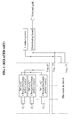
- FIG. 1 illustrates a charge/discharge system according to a related art.
- FIG. 2 illustrates a DC microgrid charge/discharge system according to an embodiment of the present invention.
- the DC microgrid charge/discharge system of FIG. 2 may refer to a single charge/discharge power supply with a large capacity.
- the charge/discharge system of FIG. 1 may require the same number of bidirectional DC-AC charge/discharge power sources as the number of batteries.
- manufacturing costs of the DC microgrid charge/discharge system of FIG. 2 may be reduced, and the DC microgrid charge/discharge system of FIG. 2 may have a significantly low weight and an extremely small size, and may also occupy an extremely small space during installation.
- lithium secondary battery lithium secondary battery
- secondary battery secondary battery
- battery battery
- a commercial power source may be input through a distributing board.
- the commercial power source supplied through the distributing board may be stored in a DC ESS through a bidirectional AC-to-DC (AC/DC) converter.
- AC/DC AC-to-DC
- the DC ESS may connect electrolytic condensers and/or super condensers in series or in parallel, and may have a required voltage and capacity.
- Each of the electrolytic condensers and/or super condensers may have a capacity of hundreds of faraday (F).
- power may be stored in the ESS in a DC state during discharging, despite charging and discharging not being necessarily performed at the same time.
- the power stored in the DC state may be directly used to perform charging, without a loss of conversion.
- the DC microgrid charge/discharge system may be configured to charge and discharge a battery group in which a large number of lithium secondary batteries are connected in series on tens to hundreds of trays, using a single ESS and a control apparatus.
- a power source output through a DC ESS 11 may be generated as a constant current source in a linear current source 13 through a bidirectional DC/DC converter 12, so that each battery may be charged and discharged.
- the bidirectional DC/DC converter 12 may be installed in each of trays.
- the bidirectional DC/DC converter 12 employed in the DC microgrid charge/discharge system may be designed and manufactured according to embodiments of the present invention.
- the bidirectional DC/DC converter 12 may be configured to simultaneously charge and discharge a plurality of batteries connected in series, based on a change in a load.
- the linear current source 13 may be a constant current source to further stabilize charge/discharge current, and to more stably control and supply current despite a change in a load in a final power source supplied to charge and discharge a plurality of batteries connected in series. Accordingly, by adding the linear current source 13, it is advantageously possible to increase accuracy and stability during controlling of charging and discharging of a battery, compared to an apparatus employing only the bidirectional DC/DC converter 12.
- the DC ESS 11 may function to stably supply electricity to the bidirectional DC/DC converter 12. Additionally, during power outage for a predetermined period of time, the DC ESS 11 may enable charging and discharging to be continuously performed, by stably supplying electricity to the bidirectional DC/DC converter 12.
- the DC ESS 11 may include, for example, an apparatus capable of supplying required power to the bidirectional DC/DC converter 12 in real time, while storing power received from the commercial power source in real time.
- the bidirectional DC/DC converter 12 and the linear current source 13 may be installed in each of the trays, so that each of a plurality of batteries 24 connected in series may be charged and discharged.
- Charging and discharging may be performed using the linear current source 13 and accordingly, it is possible to stably perform charging and discharging, regardless of the number of the batteries 24. Thus, it is possible to efficiently charge and discharge tens to hundreds of batteries, regardless of a change in voltage based on the number of batteries that are connected in series.
- a voltage may be increased by the number of batteries that are connected in series and accordingly, power conversion efficiency of the bidirectional DC/DC converter 12 may be remarkably increased.
- power may be converted by increasing a voltage of both ends of a battery group by connecting plurality of batteries in series and accordingly, energy efficiency may be increased over 80 %.
- energy efficiency may be increased over 80 %.
- a DC microgrid system may be desirably configured to set an appropriate voltage of the DC microgrid system to be about twice a maximum voltage of both ends of a battery group including batteries connected in series.
- the appropriate voltage may be changed.
- FIG. 3 illustrates an example of one of the trays of FIG. 2 .
- a single tray may include a controller 17, and a microprocessor, for example, a central processing unit (CPU) 15.
- the controller 17 may control charging and discharging of each of the batteries 24 connected in series.
- the CPU 15 may be connected to the controller 17 and a communication unit 16, and may control the controller 17.
- the controller 17 may be installed in each of the batteries 24 as shown in FIG. 3 , however, this is merely an example to facilitate understanding of the present invention. In FIG. 3 , equally assigning a number of "1" may indicate identical controllers.
- a sensor including a thermometer, a voltmeter, and an ammeter may be installed in a required position, and the controller 17 may be configured to receive, from the sensor, a measured temperature and a measured voltage of a battery, for example an open circuit voltage (OCV), and a current, a voltage and the like of a circuit.
- OCV open circuit voltage
- the controller 17 may control charging and discharging to be stably and quickly performed based on the current, the temperature, the voltage, and the like that are received from the sensor.
- V b , i b, i bb 1 to i bb 45 , a voltage between both ends of a battery, a temperature of a battery, and the like may be to be measured.
- Each of the batteries 24 may include an isolated battery management system (BMS) configured to precisely measure a voltage, a current, a temperature, and the like that indicate a state of each of the batteries 24 when the batteries 24 are isolated from each other.
- BMS battery management system
- a control program may be loaded in a memory of the controller 17.
- the control program may include a unit that is designed and manufactured according to embodiments of the present invention and that is configured to efficiently, simultaneously charge and discharge the batteries 24 with different capacities, using the linear current source 13.
- the CPU 15 installed in each of the trays may be connected to the control apparatus of FIG. 2 , for example, a host personal computer (PC) 14, and may be configured to exchange signals with the host PC 14 using a wired or wireless communication unit.
- PC personal computer
- a main circuit used to perform charging and discharging may be represented by a bold black line of FIG. 2 , and it may be easily understood that charging and discharging are performed while a constant current supplied from a linear current source passes through each of batteries connected in series.
- the batteries 24 may have different capacities and different charge/discharge characteristics for each manufacturer. Also, batteries manufactured by the same manufacturer may have different capacities and different characteristics.
- a temperature of each of the secondary batteries may be measured using a temperature sensor, a voltage between both ends of each of the secondary batteries (for example, a real-time voltage, or an OCV) may be measured, and the measured temperature and the measured voltage may be transmitted to a controller.
- the controller may control a relay to be turned on or off, or may allow an active balancing circuit to perform controlling.
- the controller 17 may control charging and discharging based on a capacity, and a characteristic including an internal resistance value of each of the batteries.
- a relay may control charging and discharging.
- an active balancing circuit 18 of FIG. 3 may operate to control charging and discharging.
- the active balancing circuit 18 may control a current i bb 1 between both ends of a relay by turning on or off a switching element of the active balancing circuit 18, and may control a value of a current i c 1 flowing to a 1 st battery.
- PWM pulse width modulation
- the active balancing circuit 18 may open and close a charging current of each of the secondary batteries based on a PWM signal output from the controller 17, or may compute the PWM signal to a DC, and may consume or bypass a part of the charging current.
- a protection circuit may be installed between both ends of a relay.
- the protection circuit may prevent a current flow from being interrupted due to opening of a circuit when a relay moves from a contact to another contact, may prevent a contact from being damaged by a spark generated when the contact is open, may increase durability of the relay, and may induce a stable operation of the circuit.
- the protection circuit may prevent opening of the circuit and damage of the contact by bypassing a current immediately when the relay is open, so that the circuit may stably operate and the durability of the relay may increase.
- the protection circuit may include a diode or a bidirectional zener diode with a large capacity, a condenser, a resistor, and the like.
- a relay controller 20 may be installed in each of the batteries 24, and may control a current flowing to each of the batteries 24 by opening or closing the relay based on a control signal of the controller 17.
- a terminal connection unit 23 may correspond to a terminal connected to charge and discharge each of batteries connected in series.
- the relay and the active balancing circuit 18 may be used as important technical components in embodiments of the present invention. Using the relay and the active balancing circuit 18, charging of secondary batteries having different capacities and different characteristics including internal resistance may be completed at the maximum voltage in a charging completion current state that is set in advance.
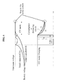
- FIG. 4 illustrates a technical configuration of charging tens to hundreds of secondary batteries in a single tray in an optimum state at the same time by a control program loaded in a controller according to an embodiment of the present invention.
- the "charging of the secondary batteries in the single tray in the optimum state” may indicate repeating charging and discharging of each of batteries connected in series at a maximum voltage by turning on or off a relay in a constant current (CC) mode until a battery with a largest capacity among the batteries lastly reaches the maximum voltage.
- CC constant current
- a CV mode may be performed.
- charging may be completed.
- the above control may be performed under a control of the controller based on a value measured by the above-described sensor, by a control program loaded in a memory of the controller.
- two batteries are assumed to have different capacities, and the same internal resistance.
- the two batteries may be controlled in the CC mode until a large-capacity battery reaches a maximum voltage.
- the other battery that is, a small-capacity battery may reach the maximum voltage, earlier than the large-capacity battery.
- charging and discharging may continue to be performed by turning on or off a relay.
- the large-capacity battery When reaching the maximum voltage, the large-capacity battery may operate in the CV mode, and a duty ratio of an active balancing circuit may be controlled so that a voltage of the small-capacity battery may not exceed a set maximum voltage value.
- a charging completion value indicating that currents input to all the batteries are set to be identical to each other at the maximum voltage, charging may be completed.
- the above-described controlling may be performed under the control of the controller.
- the controller may measure a voltage of both ends of each of batteries during charging. When the measured voltage reaches a maximum voltage, the controller may turn off the relay and may prevent a current from flowing to a corresponding battery, so that the charging may not be performed.
- An operation of charging a battery by turning on a relay when a voltage of the battery continuous to be measured and is determined to be reduced to a set voltage may be repeated until a point in time at which a last battery among a plurality of batteries connected in series in a single tray reaches a maximum voltage.
- Controlling may be performed by switching to the CV mode after the point in time.
- the CV mode may be enabled in a set maximum voltage area of FIG. 4 .
- controlling may be performed by the active balancing circuit 18 of FIG. 3 , and the value of the current i c 1 flowing to the 1 st battery may be obtained by subtracting a value of the current i bb 1 from a value of a current i b.
- a value of a current i c 2 flowing to a 2 nd battery may be obtained by subtracting a value of a current i bb 2 from the value of the current i b
- a value of a current i c 45 flowing to a 45 th battery may be obtained by subtracting a value of a current i bb 45 from the value of the current i b.
- a current may flow directly to a battery disposed in a lower side of the corresponding battery.
- the active balancing circuit 18 of FIG. 3 may include a control element, for example, a switching element, a plurality of circuit elements, and the like, may operate under the control of the controller 17, and may be controlled by several methods that will be described below.
- a control element for example, a switching element, a plurality of circuit elements, and the like
- an active balancing circuit may turn on and off a gate (that is, a base), and may control a current flowing in both ends of a corresponding battery (for example, currents i bb 1 to i bb 45 ).
- an active balancing circuit may control a current control circuit to convert a PWM signal output from a controller to a current that is in proportion to a duty ratio, and to directly supply the current, and an equal effect may be generated.
- the above method may have an advantageous effect of preventing electric noise from being generated when the active balancing circuit operates.
- the controller 17 may control a duty ratio and a frequency of a PWM signal, may supply the PWM signal, and may control a current flowing in both ends of each of the batteries 24 (for example, the currents i bb 1 to i bb 45 ).
- the currents i bb 1 to i bb 45 When currents flowing to all batteries connected in series in a single tray (for example, the currents i c 1 to i c 45 ) have the save values as the preset charging completion current value, charging may be completed.
- a DC microgrid charge/discharge system may be connected to a host PC, for example the control apparatus of FIG. 2 , and may simultaneously control tens or hundreds of trays. In each of the trays, a plurality of batteries may be connected in series, as described above. Additionally, charging and discharging may be performed by a single bidirectional DC/DC converter, a single linear current source, a relay, and an active balancing circuit.
- the above-described relay may be replaced by a switching circuit or a switching element having an equal function.
- the above-described technical configuration according to embodiments of the present invention may have an effect of noticeably increasing an operating voltage by connecting a plurality of predetermined secondary batteries in series, of performing charging and discharging using a single bidirectional DC/DC converter and a linear current source (that is, a constant current source), and of dramatically increasing power efficiency by directly using discharged electricity in a DC form in a charging apparatus, unlike a conventional method of charging and discharging each of secondary batteries with relatively low voltages, for example, voltages of 2 V to 4.7 V.
- the same number of power supplies for charging and discharging as the number of batteries is used.
- a single bidirectional DC/DC converter with a large capacity, and a single linear current source may be used and thus, it is possible to manufacture a compact and lightweight apparatus, and possible to reduce manufacturing costs and installation space.
- a single large-capacity power supply for charging and discharging may require an extremely small size and weight, and may be installed in extremely small space, compared to a related art requiring the same number of power supplies for charging and discharging as the number of batteries.
- charging and discharging of a plurality of batteries connected in series may be controlled by a single bidirectional DC/DC converter and a single linear current source, regardless of the number of the batteries.
- a single bidirectional DC/DC converter and a single linear current source regardless of the number of the batteries.
- Embodiments of the present invention may provide an algorithm and a DC microgrid charge/discharge system with the algorithm that noticeably increases charge/discharge voltage by connecting a plurality of secondary batteries in series, compared to a single battery, that increases power conversion efficiency of a bidirectional DC/DC converter, that achieves optimum energy conversion efficiency by setting an appropriate voltage of a DC microgrid that directly uses discharged DC electricity to perform charging to be about twice a maximum voltage of a battery group, that increases power conversion efficiency of the DC microgrid charge/discharge system by configuring a DC ESS used for charge/discharge with a combination of a typical electrolytic condenser and a super condenser or a group of the secondary batteries, and that simplifies the DC microgrid charge/discharge system.
- a DC ESS used for charge/discharge with a combination of a typical electrolytic condenser and a super condenser or a group of the secondary batteries
Landscapes
- Engineering & Computer Science (AREA)
- Power Engineering (AREA)
- Transportation (AREA)
- Mechanical Engineering (AREA)
- Life Sciences & Earth Sciences (AREA)
- Sustainable Development (AREA)
- Sustainable Energy (AREA)
- Charge And Discharge Circuits For Batteries Or The Like (AREA)
- Secondary Cells (AREA)
Applications Claiming Priority (1)
| Application Number | Priority Date | Filing Date | Title |
|---|---|---|---|
| KR1020130032882A KR101451009B1 (ko) | 2013-03-27 | 2013-03-27 | 직렬 연결된 다수 개의 전지 직류 마이크로그리드 충방전 시스템 |
Publications (1)
| Publication Number | Publication Date |
|---|---|
| EP2784902A1 true EP2784902A1 (de) | 2014-10-01 |
Family
ID=50442345
Family Applications (1)
| Application Number | Title | Priority Date | Filing Date |
|---|---|---|---|
| EP14161787.8A Withdrawn EP2784902A1 (de) | 2013-03-27 | 2014-03-26 | Gleichstrommikrogitter-Lade-/Entladesystem für reihengeschaltete Sekundärbatterien |
Country Status (5)
| Country | Link |
|---|---|
| US (1) | US9455578B2 (de) |
| EP (1) | EP2784902A1 (de) |
| JP (1) | JP5959561B2 (de) |
| KR (1) | KR101451009B1 (de) |
| CN (1) | CN104079056B (de) |
Cited By (2)
| Publication number | Priority date | Publication date | Assignee | Title |
|---|---|---|---|---|
| EP2808689A2 (de) * | 2013-05-15 | 2014-12-03 | LG CNS Co., Ltd. | Überwachung für Batteriekontaktpunkt in Lade-/Entladesystem mit in Reihe geschalteten Batterien |
| EP2804286A3 (de) * | 2013-05-15 | 2015-01-07 | LG CNS Co., Ltd. | Vorrichtung und Verfahren mit aktiver Ausgleichsschaltung und aktivem Ausgleichsalgorithmus zum Laden und Entladen von in Reihe geschalteten Sekundärbatterien |
Families Citing this family (39)
| Publication number | Priority date | Publication date | Assignee | Title |
|---|---|---|---|---|
| US9401501B2 (en) | 2012-05-18 | 2016-07-26 | 24M Technologies, Inc. | Electrochemical cells and methods of manufacturing the same |
| US9312699B2 (en) | 2012-10-11 | 2016-04-12 | Flexgen Power Systems, Inc. | Island grid power supply apparatus and methods using energy storage for transient stabilization |
| US10289080B2 (en) | 2012-10-11 | 2019-05-14 | Flexgen Power Systems, Inc. | Multi-generator applications using variable speed and solid state generators for efficiency and frequency stabilization |
| US9553517B2 (en) | 2013-03-01 | 2017-01-24 | Fllexgen Power Systems, Inc. | Hybrid energy storage system and methods |
| DE102013204885A1 (de) * | 2013-03-20 | 2014-09-25 | Robert Bosch Gmbh | Verfahren zur Reduzierung des Gesamtladungsverlusts von Batterien |
| DE102013204888A1 (de) * | 2013-03-20 | 2014-09-25 | Robert Bosch Gmbh | Verfahren zum Ausgleich unterschiedlicher Ladungszustände von Batterien |
| DE102014200858A1 (de) * | 2014-01-17 | 2015-07-23 | TRUMPF Hüttinger GmbH + Co. KG | Energiespeichersystem und Verfahren zum Steigern der Effizienz eines Energiespeichersystems |
| JP2017531983A (ja) | 2014-10-13 | 2017-10-26 | 24エム・テクノロジーズ・インコーポレイテッド24M Technologies, Inc. | 直列電池充電及び形成用のシステム及び方法 |
| CN107112444B (zh) | 2014-11-05 | 2021-01-26 | 24M技术公司 | 具有半固体电极的电化学电池及其制造方法 |
| US9812863B2 (en) * | 2014-12-18 | 2017-11-07 | Solantro Semiconductor Corp. | Distributed electrical microgrid control |
| US10574055B2 (en) | 2014-12-30 | 2020-02-25 | Flexgen Power Systems, Inc. | Transient power stabilization device with active and reactive power control |
| CA2969135C (en) | 2015-06-18 | 2026-03-17 | Kyocera Corporation | Single pouch battery cells and methods of manufacture |
| KR101698831B1 (ko) * | 2015-10-06 | 2017-02-13 | 한국에너지기술연구원 | 정전시 가동을 유지하기 위한 전력 안전 공급 장치 및 이의 제어 방법 |
| US11031792B2 (en) * | 2016-08-05 | 2021-06-08 | Ge Energy Power Conversion Technology Ltd | Battery charging control system and method of operation thereof |
| WO2018107065A1 (en) * | 2016-12-11 | 2018-06-14 | Sandeep Agarwal | Smart energy storage system |
| CN107370171B (zh) * | 2017-07-13 | 2021-07-06 | 北京索英电气技术有限公司 | 一种独立微网中大规模储能优化配置与协调控制方法 |
| CN109755972A (zh) * | 2017-11-01 | 2019-05-14 | 北京德意新能电气有限公司 | 一种储能电池串并联均衡控制策略 |
| US10444295B2 (en) * | 2017-12-20 | 2019-10-15 | National Chung Shan Institute Of Science And Technology | Battery balance management circuit |
| US11594883B2 (en) * | 2018-01-23 | 2023-02-28 | Tdk Corporation | Direct current power supplying system |
| CN109193881A (zh) * | 2018-11-23 | 2019-01-11 | 北斗航天汽车(北京)有限公司 | 带有快速充电功能的电池包及快速充电方法 |
| CN110588438B (zh) * | 2019-09-18 | 2024-04-30 | 深圳市科列技术股份有限公司 | 汽车电池管理系统主动均衡矩阵开关的供电及驱动电路 |
| CN110994743A (zh) * | 2019-12-27 | 2020-04-10 | 北京兴达智联科技有限公司 | 一种受控型电池组装置及其充放电控制方法 |
| US11742525B2 (en) | 2020-02-07 | 2023-08-29 | 24M Technologies, Inc. | Divided energy electrochemical cell systems and methods of producing the same |
| US11404887B2 (en) * | 2020-02-14 | 2022-08-02 | Techtronic Cordless Gp | Battery charging and discharging using a battery bank during battery manufacture |
| KR102448544B1 (ko) * | 2020-04-09 | 2022-09-29 | 주식회사 원익피앤이 | 모듈화 형태의 고정밀 충방전기 서브렉 조립구조 |
| US12381277B2 (en) | 2020-06-17 | 2025-08-05 | 24M Technologies, Inc. | Electrochemical cells with flame retardant mechanism and methods of producing the same |
| KR102654847B1 (ko) * | 2020-06-23 | 2024-04-05 | 현대자동차주식회사 | 배터리 밸런싱 장치 및 방법 |
| KR102654899B1 (ko) * | 2020-11-13 | 2024-04-03 | 주식회사 엘지에너지솔루션 | 배터리 활성화를 위한 직류 배전 기반의 충방전 시스템 |
| CN112467839B (zh) | 2020-11-23 | 2023-09-29 | 阳光电源股份有限公司 | 一种电池簇管理装置及电池储能系统 |
| KR102262789B1 (ko) | 2020-12-29 | 2021-06-09 | (주)한빛레이저 | 전류의 단속이 없는 직렬형충방전 장치 |
| WO2022145581A1 (ko) | 2020-12-29 | 2022-07-07 | 주식회사 한빛레이저 | 전류의 단속이 없는 직렬형충방전 장치 및 방법 |
| KR102299482B1 (ko) | 2021-02-22 | 2021-09-07 | (주)한빛레이저 | 전류의 단속이 없는 직렬형충방전 방법 |
| JP7371643B2 (ja) * | 2021-01-06 | 2023-10-31 | トヨタ自動車株式会社 | 制御装置、制御プログラム及び制御システム |
| CN113306450A (zh) * | 2021-06-25 | 2021-08-27 | 深圳市瑞能实业股份有限公司 | 一种串联化成恒压充电电路 |
| WO2023153843A1 (ko) | 2022-02-11 | 2023-08-17 | 주식회사 엘지에너지솔루션 | 배터리 셀 충전 방법 및 충전 시스템 |
| KR102429765B1 (ko) | 2022-02-11 | 2022-08-05 | 주식회사 원익피앤이 | 배터리 충방전 장치 |
| KR20230121538A (ko) | 2022-02-11 | 2023-08-18 | 주식회사 엘지에너지솔루션 | 배터리 셀 충전 방법 및 충전 시스템 |
| US12418179B2 (en) * | 2022-06-02 | 2025-09-16 | Honeywell International Inc. | System and apparatus for the control of battery energy storage systems |
| US20250196717A1 (en) * | 2023-12-19 | 2025-06-19 | GM Global Technology Operations LLC | Active battery state-of-charge balancing |
Citations (10)
| Publication number | Priority date | Publication date | Assignee | Title |
|---|---|---|---|---|
| DE10035959A1 (de) * | 1999-07-30 | 2001-04-26 | Sanyo Electric Co | Verfahren zum Entladen einer Vielzahl von wiederaufladbaren Batterien und Batteriebaugruppe |
| WO2004030177A1 (en) * | 2002-09-26 | 2004-04-08 | Eaton Power Quality Limited | Modular battery management apparatus with cell sensing and energy redistribution capabilities |
| US20060261783A1 (en) * | 2005-05-23 | 2006-11-23 | Paul Gamboa | Electronic battery module (EBM) with bidirectional DC-DC converter |
| WO2009131336A2 (en) * | 2008-04-22 | 2009-10-29 | Sk Energy Co., Ltd. | Two-stage charge equalization method and apparatus for series-connected battery string |
| WO2010084494A1 (en) * | 2009-01-22 | 2010-07-29 | Techtium Ltd. | Intelligent battery powered charging system |
| WO2010087608A2 (en) * | 2009-01-30 | 2010-08-05 | Sk Energy Co., Ltd. | Charge equalization apparatus and method for series-connected battery string |
| KR20100119574A (ko) | 2008-02-18 | 2010-11-09 | 파나소닉 주식회사 | 충전 제어 회로, 및 이것을 구비하는 충전 장치, 전지 팩 |
| KR20100122911A (ko) | 2008-02-25 | 2010-11-23 | 이와사키 덴끼 가부시키가이샤 | 충전 장치 및 충전 방법 |
| US20110140513A1 (en) * | 2009-12-15 | 2011-06-16 | Messier-Dowty Inc. | Electric accumulator utilizing an ultra-capacitor array |
| KR20120103337A (ko) | 2011-03-10 | 2012-09-19 | 삼성에스디아이 주식회사 | 2차 전지 충방전 시스템 및 그 구동 방법 |
Family Cites Families (20)
| Publication number | Priority date | Publication date | Assignee | Title |
|---|---|---|---|---|
| JP3002623B2 (ja) * | 1993-12-03 | 2000-01-24 | 富士電気化学株式会社 | 直列電池の過放電防止回路、過充電防止回路および充放電制御回路 |
| JPH08265987A (ja) * | 1995-03-20 | 1996-10-11 | Integuran Kk | 直列電池の充電電圧分配装置 |
| JPH1155866A (ja) * | 1997-08-04 | 1999-02-26 | Denso Corp | バッテリの充電装置 |
| JP2000312442A (ja) * | 1999-04-23 | 2000-11-07 | Hitachi Ltd | 直列電池充放電装置 |
| US7557538B2 (en) * | 2001-09-03 | 2009-07-07 | Gpe International Limited | Intelligent serial battery charger |
| JP4126167B2 (ja) | 2001-09-13 | 2008-07-30 | 三菱重工業株式会社 | 直列接続の電池群の充放電回路 |
| KR20060078967A (ko) * | 2004-12-31 | 2006-07-05 | 주식회사 엠피에스 | 직렬 연결된 2차 조합전지의 밸런스 충전 제어 방법 |
| US8519671B2 (en) * | 2008-09-15 | 2013-08-27 | Blackberry Limited | Power supply circuit and method for providing output voltage to charge a battery |
| KR101093597B1 (ko) | 2009-01-30 | 2011-12-15 | 한국과학기술원 | 정전압원을 이용한 자동전하균일 장치 |
| US9397502B2 (en) * | 2009-03-02 | 2016-07-19 | Volterra Semiconductor LLC | System and method for proportioned power distribution in power converter arrays |
| KR20100101994A (ko) * | 2009-03-10 | 2010-09-20 | 엘에스산전 주식회사 | 전기자동차용 충전시스템 |
| US8139384B2 (en) * | 2009-06-02 | 2012-03-20 | Power Integrations, Inc. | Method and apparatus for input charge control of a power supply |
| CN102460198B (zh) * | 2009-06-24 | 2014-09-10 | 日本碍子株式会社 | 电池控制装置和电池控制方法 |
| US8159178B2 (en) * | 2009-08-21 | 2012-04-17 | Xantrex Technology Inc. | AC connected modules with line frequency or voltage variation pattern for energy control |
| EP2325970A3 (de) | 2009-11-19 | 2015-01-21 | Samsung SDI Co., Ltd. | Energieverwaltungssystem und netzgebundenes Energiespeichersystem mit dem Energieverwaltungssystem |
| SG186432A1 (en) * | 2010-06-21 | 2013-01-30 | Univ Singapore | Energy storage system |
| US8436582B2 (en) * | 2010-07-09 | 2013-05-07 | Freescale Semiconductor, Inc. | Battery cell equalizer system |
| JP2013116006A (ja) * | 2011-11-30 | 2013-06-10 | Toyota Industries Corp | 電池均等化装置および方法 |
| WO2014076832A1 (ja) * | 2012-11-19 | 2014-05-22 | 株式会社日立製作所 | 蓄電池制御装置及び蓄電地制御方法 |
| KR101397887B1 (ko) * | 2013-05-15 | 2014-05-20 | 주식회사 엘지씨엔에스 | 다수의 전지를 직렬 연결한 충방전 시스템에서의 전지접촉부 감시 장치 및 방법 |
-
2013
- 2013-03-27 KR KR1020130032882A patent/KR101451009B1/ko active Active
-
2014
- 2014-03-26 EP EP14161787.8A patent/EP2784902A1/de not_active Withdrawn
- 2014-03-26 CN CN201410116756.2A patent/CN104079056B/zh active Active
- 2014-03-26 US US14/226,412 patent/US9455578B2/en active Active
- 2014-03-26 JP JP2014063031A patent/JP5959561B2/ja active Active
Patent Citations (10)
| Publication number | Priority date | Publication date | Assignee | Title |
|---|---|---|---|---|
| DE10035959A1 (de) * | 1999-07-30 | 2001-04-26 | Sanyo Electric Co | Verfahren zum Entladen einer Vielzahl von wiederaufladbaren Batterien und Batteriebaugruppe |
| WO2004030177A1 (en) * | 2002-09-26 | 2004-04-08 | Eaton Power Quality Limited | Modular battery management apparatus with cell sensing and energy redistribution capabilities |
| US20060261783A1 (en) * | 2005-05-23 | 2006-11-23 | Paul Gamboa | Electronic battery module (EBM) with bidirectional DC-DC converter |
| KR20100119574A (ko) | 2008-02-18 | 2010-11-09 | 파나소닉 주식회사 | 충전 제어 회로, 및 이것을 구비하는 충전 장치, 전지 팩 |
| KR20100122911A (ko) | 2008-02-25 | 2010-11-23 | 이와사키 덴끼 가부시키가이샤 | 충전 장치 및 충전 방법 |
| WO2009131336A2 (en) * | 2008-04-22 | 2009-10-29 | Sk Energy Co., Ltd. | Two-stage charge equalization method and apparatus for series-connected battery string |
| WO2010084494A1 (en) * | 2009-01-22 | 2010-07-29 | Techtium Ltd. | Intelligent battery powered charging system |
| WO2010087608A2 (en) * | 2009-01-30 | 2010-08-05 | Sk Energy Co., Ltd. | Charge equalization apparatus and method for series-connected battery string |
| US20110140513A1 (en) * | 2009-12-15 | 2011-06-16 | Messier-Dowty Inc. | Electric accumulator utilizing an ultra-capacitor array |
| KR20120103337A (ko) | 2011-03-10 | 2012-09-19 | 삼성에스디아이 주식회사 | 2차 전지 충방전 시스템 및 그 구동 방법 |
Cited By (3)
| Publication number | Priority date | Publication date | Assignee | Title |
|---|---|---|---|---|
| EP2808689A2 (de) * | 2013-05-15 | 2014-12-03 | LG CNS Co., Ltd. | Überwachung für Batteriekontaktpunkt in Lade-/Entladesystem mit in Reihe geschalteten Batterien |
| EP2804286A3 (de) * | 2013-05-15 | 2015-01-07 | LG CNS Co., Ltd. | Vorrichtung und Verfahren mit aktiver Ausgleichsschaltung und aktivem Ausgleichsalgorithmus zum Laden und Entladen von in Reihe geschalteten Sekundärbatterien |
| US9559528B2 (en) | 2013-05-15 | 2017-01-31 | Hbl Corporation | Apparatus and method with active balancing circuit and active balancing algorithm for charging and discharging secondary batteries connected in series |
Also Published As
| Publication number | Publication date |
|---|---|
| US20140292259A1 (en) | 2014-10-02 |
| JP2014193111A (ja) | 2014-10-06 |
| JP5959561B2 (ja) | 2016-08-02 |
| KR20140117923A (ko) | 2014-10-08 |
| KR101451009B1 (ko) | 2014-10-15 |
| US9455578B2 (en) | 2016-09-27 |
| CN104079056A (zh) | 2014-10-01 |
| CN104079056B (zh) | 2017-03-01 |
Similar Documents
| Publication | Publication Date | Title |
|---|---|---|
| US9455578B2 (en) | Direct current (DC) microgrid charge/discharge system for secondary batteries connected in series | |
| US9559528B2 (en) | Apparatus and method with active balancing circuit and active balancing algorithm for charging and discharging secondary batteries connected in series | |
| KR102379377B1 (ko) | 전기 화학 임피던스 분광을 위한 전기 아키텍처 | |
| EP3259152B1 (de) | Stromverteilungssystem für ein elektrofahrzeug | |
| CN102655342B (zh) | 电源系统 | |
| US10629961B2 (en) | Cell balancing system and control method | |
| US11146094B2 (en) | Electrical apparatus | |
| JPWO2020022344A1 (ja) | 電源システム、及び管理装置 | |
| US11159031B2 (en) | Electrical machinery and apparatus | |
| US12589674B2 (en) | Power supply system | |
| US20230163374A1 (en) | Charge and discharge control device and charge and discharge control method | |
| CN204928206U (zh) | 针对多个电池/电池备用单元匹配寿命终止的系统 | |
| JP2022066025A (ja) | 蓄電装置、その充電方法、および、その充電制御プログラム | |
| KR102945610B1 (ko) | 배터리 충방전 시험 장치 및 이를 이용한 충방전 시험 방법 | |
| US9443684B2 (en) | Charging and discharging control apparatus of DC link capacitor in electric power steering relay and method thereof | |
| KR20230047575A (ko) | 배터리 모듈 밸런싱 장치 및 방법 | |
| KR20230056120A (ko) | 연료전지 시스템 및 그의 전압 밸런싱 제어 방법 |
Legal Events
| Date | Code | Title | Description |
|---|---|---|---|
| 17P | Request for examination filed |
Effective date: 20140326 |
|
| AK | Designated contracting states |
Kind code of ref document: A1 Designated state(s): AL AT BE BG CH CY CZ DE DK EE ES FI FR GB GR HR HU IE IS IT LI LT LU LV MC MK MT NL NO PL PT RO RS SE SI SK SM TR |
|
| AX | Request for extension of the european patent |
Extension state: BA ME |
|
| PUAI | Public reference made under article 153(3) epc to a published international application that has entered the european phase |
Free format text: ORIGINAL CODE: 0009012 |
|
| RBV | Designated contracting states (corrected) |
Designated state(s): AL AT BE BG CH CY CZ DE DK EE ES FI FR GB GR HR HU IE IS IT LI LT LU LV MC MK MT NL NO PL PT RO RS SE SI SK SM TR |
|
| 17Q | First examination report despatched |
Effective date: 20170127 |
|
| STAA | Information on the status of an ep patent application or granted ep patent |
Free format text: STATUS: THE APPLICATION IS DEEMED TO BE WITHDRAWN |
|
| 18D | Application deemed to be withdrawn |
Effective date: 20180328 |