EP2785092A1 - Système de communication sans fil - Google Patents
Système de communication sans fil Download PDFInfo
- Publication number
- EP2785092A1 EP2785092A1 EP13161686.4A EP13161686A EP2785092A1 EP 2785092 A1 EP2785092 A1 EP 2785092A1 EP 13161686 A EP13161686 A EP 13161686A EP 2785092 A1 EP2785092 A1 EP 2785092A1
- Authority
- EP
- European Patent Office
- Prior art keywords
- coverage
- terminals
- base station
- terminal
- wireless communication
- Prior art date
- Legal status (The legal status is an assumption and is not a legal conclusion. Google has not performed a legal analysis and makes no representation as to the accuracy of the status listed.)
- Granted
Links
Images



Classifications
-
- H—ELECTRICITY
- H04—ELECTRIC COMMUNICATION TECHNIQUE
- H04W—WIRELESS COMMUNICATION NETWORKS
- H04W16/00—Network planning, e.g. coverage or traffic planning tools; Network deployment, e.g. resource partitioning or cells structures
- H04W16/02—Resource partitioning among network components, e.g. reuse partitioning
- H04W16/06—Hybrid resource partitioning, e.g. channel borrowing
-
- H—ELECTRICITY
- H04—ELECTRIC COMMUNICATION TECHNIQUE
- H04W—WIRELESS COMMUNICATION NETWORKS
- H04W16/00—Network planning, e.g. coverage or traffic planning tools; Network deployment, e.g. resource partitioning or cells structures
-
- H—ELECTRICITY
- H04—ELECTRIC COMMUNICATION TECHNIQUE
- H04W—WIRELESS COMMUNICATION NETWORKS
- H04W16/00—Network planning, e.g. coverage or traffic planning tools; Network deployment, e.g. resource partitioning or cells structures
- H04W16/02—Resource partitioning among network components, e.g. reuse partitioning
- H04W16/06—Hybrid resource partitioning, e.g. channel borrowing
- H04W16/08—Load shedding arrangements
-
- H—ELECTRICITY
- H04—ELECTRIC COMMUNICATION TECHNIQUE
- H04W—WIRELESS COMMUNICATION NETWORKS
- H04W36/00—Hand-off or reselection arrangements
- H04W36/0005—Control or signalling for completing the hand-off
- H04W36/0055—Transmission or use of information for re-establishing the radio link
- H04W36/0061—Transmission or use of information for re-establishing the radio link of neighbour cell information
-
- H—ELECTRICITY
- H04—ELECTRIC COMMUNICATION TECHNIQUE
- H04W—WIRELESS COMMUNICATION NETWORKS
- H04W72/00—Local resource management
- H04W72/50—Allocation or scheduling criteria for wireless resources
- H04W72/51—Allocation or scheduling criteria for wireless resources based on terminal or device properties
-
- H—ELECTRICITY
- H04—ELECTRIC COMMUNICATION TECHNIQUE
- H04W—WIRELESS COMMUNICATION NETWORKS
- H04W76/00—Connection management
- H04W76/10—Connection setup
- H04W76/14—Direct-mode setup
-
- H—ELECTRICITY
- H04—ELECTRIC COMMUNICATION TECHNIQUE
- H04W—WIRELESS COMMUNICATION NETWORKS
- H04W88/00—Devices specially adapted for wireless communication networks, e.g. terminals, base stations or access point devices
- H04W88/02—Terminal devices
- H04W88/04—Terminal devices adapted for relaying to or from another terminal or user
Definitions
- Embodiments of the present application relate generally to wireless communication systems and in particular, but not exclusively, to managing coverage provided by base stations of such wireless communication systems.
- Wireless communication systems are widely known in which base stations (or access points) communicate wirelessly with terminals (also called user equipments, mobile stations or subscriber stations) within range of the base stations.
- the geographical area covered by a base station is generally referred to as a cell, and typically many base stations are provided in appropriate locations so as to cover a wider geographical area more or less seamlessly with adjacent and/or overlapping cells.
- the size of a cell can be influenced by a number of factors including transmission power, pathloss, interference, and the like.
- a terminal may be in range of (i.e. be able to directly communicate with) several base stations at the same time, but in the simplest case the terminal communicates with one 'serving' base station.
- a method of operating a wireless communication system comprising one or more base stations each configured to provide a corresponding coverage in use, a particular one of the base stations providing coverage to one or more in-coverage terminals, there being one or more out-of-coverage terminals outside the coverage provided by the particular base station, the method comprising determining whether a condition related to direct device-to-device wireless communication between the in-coverage terminals and the out-of-coverage terminals is satisfied; and if the condition is satisfied, changing at least one of the coverage of the particular base station and the coverage of another one of the base stations, so as to provide coverage to one or more of the out-of-coverage terminals.
- the wireless communication system may comprise infrastructure resources of multiple wireless communication systems (or networks).
- the wireless communication system may comprise a mix of LTE cellular base stations and WiFi base stations (access points).
- the term “coverage” or “coverage area” is used herein to denote a communication capability between a base station and a terminal, whether direct or via a relay terminal.
- the communication capability may be specified, for example, in terms of satisfying a required channel quality metric such as Signal to Interference and Noise Ratio, SINR, or the like.
- SINR Signal to Interference and Noise Ratio
- the capacity of the base station is changed, i.e. the number of active terminals changes, for example when terminals which were not previously served are admitted.
- the terms “coverage” and “capacity” may be used interchangeably where appropriate.
- the condition may comprise one or more of: a number of requests for device-to-device communication received by the in-coverage terminals from the out-of-coverage terminals, a number of the in-coverage terminals that are configured and/or enabled to support direct device-to-device wireless communication, and a number of the in-coverage terminals that have available resources to serve as relays between the particular base station and the out-of-coverage terminals.
- the condition can therefore serve as an indicator for how to change the coverage.
- the number can be one or more than one.
- the method further comprises the particular base station receiving information about the out-of-coverage terminals from the in-coverage terminals. This enables a more informed decision to be made as to how to serve the out-of-coverage terminals.
- Changing the coverage may comprise extending the coverage of the serving base station.
- the coverage of the serving base station can be extended by changing an operating parameter of the serving base station to allow the serving base station to directly communicate with at least one of the out-of-coverage terminals.
- the coverage of the serving base station can be extended by selecting at least one of the in-coverage terminals to serve as a relay between the serving base station and at least one of the out-of-coverage terminals.
- a base station may therefore serve the out-of-coverage terminal either directly, through a communication path without an intermediary, or indirectly, through a communication path that includes a direct device-to-device communication link.
- changing the coverage comprises at least one of: provisioning of a new radio resource to the out-of-coverage terminals, provisioning of an existing radio resource to the out-of-coverage terminals, and using a first radio resource for direct base station to terminal communication and a second radio resource for indirect base station to terminal communication.
- changing the coverage comprises admitting at least one of the out-of-coverage terminals to the system.
- changing the coverage comprises handing off at least one of the out-of-coverage terminals to the particular base station from one of the base stations that neighbours the particular base station. Such a neighbouring base station may turn off, or place on stand-by, one or more resources. This allows reduced power consumption by the base station.
- the particular base station and the neighbouring base station may share information about the out-of-coverage terminals (which may be in-coverage terminals with respect to the neighbouring base station).
- the base stations can therefore coordinate in order to ensure that there is no or minimal loss of coverage.
- changing the coverage comprises activating the other base station to provide coverage to at least one of the out-of-coverage terminals.
- the activated base station may be used to fill coverage gaps of the base station.
- the base station may be activated in response to a request or an instruction from at least one of the in-coverage terminals.
- the method further comprises at least one of the in-coverage terminals transmitting a discovery signal indicating that it can serve as a relay between the particular base station and out-of-coverage terminals. This provides a mechanism for in-coverage terminals to advertise their capability to act as relays to out-of-coverage terminals.
- the method may further comprise the serving base station scheduling the in-coverage terminal to transmit the discovery signal. This allows the base station retain a degree of control over the transmission of discovery signals.
- the in-coverage terminals which transmit the discovery signal may be selected by the serving base station based on a throughput criterion.
- the throughput criterion can include, for example, one or more of a fill level of a buffer, a SNR, a battery level, and a mobility of the in-coverage terminal.
- An in-coverage terminal that meets one or more throughput criterion for example has a low buffer fill level, a high SNR, a high battery level, and/or is substantially stationary, is more likely to be suitable to act as relays for an out-of-coverage terminal.
- the discovery signal is transmitted by the in-coverage terminal using a frequency hopping scheme. This increases the chance of discovery by out-of-coverage terminals that are configured to support relatively narrow and different discovery bandwidths.
- the discovery signal can be transmitted at configurable time intervals, for example at periodic time interval set by the serving base station.
- the length of the periodic time interval is set according to a transmission condition, the transmission condition comprising one or more of: the in-coverage terminal has recently been scheduled to transmit the discovery signal, and an estimated channel quality of the in-coverage terminal is greater than a predetermined threshold. For example, longer time intervals can be set if the in-coverage terminal has recently been scheduled to transmit the discovery signal and/or if the estimated channel quality is greater than the predetermined threshold. In this way, the communication resources can be sparingly used.
- the discovery signal transmitted by the in-coverage terminal indicates a value of a communication parameter offered thereby. This allows an out-of-coverage terminal to judge whether an in-coverage terminal is suitable for its needs.
- the discovery signal is a reference signal. This could be an uplink reference signal such as a sounding reference signal.
- the discovery signal according to embodiments may be interspersed with regular reference signals such as regular sounding reference signals that are used for channel estimation by the serving base station.
- a wireless communication system comprising one or more base stations each configured to provide a corresponding coverage in use, at least one of the base stations configured to: determine whether a condition related to direct device-to-device wireless communication between one or more in-coverage terminals that are within the coverage of the base station and one or more out-of-coverage terminals that are outside the coverage of the base station is satisfied, and change the coverage if the condition is satisfied so as to provide coverage to one or more of the out-of-coverage terminals.
- a base station for use in a wireless communication system, comprising a communication unit configured to provide coverage to one or more in-coverage terminals; and a controller configured to determine whether a condition related to direct device-to-device wireless communication between the in-coverage terminals and one or more out-of-coverage terminals that are outside of its coverage is satisfied, and to control the communication unit to change the coverage if the condition is satisfied.
- a terminal for use in a wireless communication system comprising one or more base stations each configured to provide a corresponding coverage in use, the terminal comprising a communication unit; and a controller configured to, when the terminal is in the coverage provided by a particular base station, control the communication unit to transmit to the particular base station information about one or more out-of-coverage terminals that is outside the coverage provided by the particular base station
- a method of advertising a relaying capability in a communication system comprising one or more base stations each configured to provide a corresponding coverage in use, a particular one of the base stations providing coverage to one or more in-coverage terminals, there being one or more out-of-coverage terminals outside the coverage provided by the particular base station, the method comprising at least one of the in-coverage terminals transmitting a signal indicating that it can serve as a relay between the serving base station and an out-of-coverage terminal.
- One embodiment provides a computer program product comprising computer executable instructions which, when executed by a computer, cause the computer to perform a method as set out above.
- the computer program product may be embodied in a carrier medium, which may be a storage medium or a signal medium.
- a storage medium may include optical storage means, or magnetic storage means, or electronic storage means.
- Embodiments may be incorporated into a specific hardware device, a general purpose device configured by suitable software, or a combination of both. Aspects can be embodied in a software product, either as a complete software implementation, or as an add-on component for modification or enhancement of existing software (such as a plug in). Such a software product could be embodied in a carrier medium, such as a storage medium (e.g. an optical disk or a mass storage memory such as a FLASH memory) or a signal medium (such as a download).
- Specific hardware devices suitable for the embodiment could include an application specific device such as an ASIC, an FPGA or a DSP, or other dedicated functional hardware means.
- Embodiments can be applied, for example, to wireless communication systems based on the Third Generation Partnership Project (3GPP) Long Term Evolution (LTE) standard, in which base stations are called eNodeBs (eNBs) and terminals are called user equipments (UEs).
- 3GPP Third Generation Partnership Project
- eNBs base stations
- UEs user equipments
- LTE Long Term Evolution
- a brief description of a wireless communication system in accordance with the Third Generation Partnership Project (3GPP) Long Term Evolution (LTE) standard is therefore provided below with reference to Figure 1 .
- the terms “wireless communication system”, “base station” and “terminal” used herein are not limited to 3GPP LTE systems, eNBs and UEs.
- a system 100 in accordance with the 3GPP LTE standard is functionally split between an evolved Universal Terrestrial Radio Access (E-UTRAN) network 105 and an Evolved Packet Core (EPC) 106, which together constitute the Evolved Packet System.
- E-UTRAN evolved Universal Terrestrial Radio Access
- EPC Evolved Packet Core
- the E-UTRAN network 105 comprises eNBs 102-1, 102-2 interconnected to each other by means of an X2 interface.
- the eNBs 102-1, 102-2 are also connected to the EPC by means of S1 interfaces.
- the EPC 106 includes (not shown) the Serving Gateway, the Mobility Management Entity, the Packet Data Network Gateway, and the Policy Charging Rules Function.
- the eNBs 102-1, 102-2 provide the radio interface toward UEs 108-1, 108-2 in the respective coverages 104-1, 104-2.
- the coverages are represented as circles, though it will be appreciated that in practice the coverage typically does not have a regular shape (whether circular, hexagonal, or otherwise).
- UEs 108-1, 108-2 communicate with each other they do so via their serving eNB 102-1, 102-2.
- 3GPP has recently started studying the use of licensed spectrum for direct, peer-to-peer communication between UEs.
- Discovery and communications between UEs that are in proximity is studied under the general umbrella of Proximity Services, also often referred to as device-to-device (D2D) communication.
- D2D device-to-device
- proximity is determined (“A UE is in proximity of another UE") when a proximity criterion or criteria are fulfilled.
- Proximity criteria can be different for discovery and communication. Examples of the criteria include, for example, communication range, channel conditions, and achievable QoS.
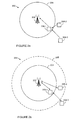
- Figures 2a and 2b schematically show how coverage of a base station can be changed, according to an embodiment.
- a wireless communication system 200 comprises base station 202 with coverage 204.
- coverage (or “coverage area”) herein denotes a communication capability between a base station and a terminal. For convenience, the term coverage will simply be used.
- terminal 208-1 is within the coverage 204 of the base station 202 and will therefore be referred to as an in-coverage terminal, while terminals 208-2, 208-3 are outside the coverage 204 of the base station 202 and will therefore be referred to as out-of-coverage terminals.
- the terminal 208-1 is located at the edge of the coverage 204 provided by base station 202.
- Each of the terminals 208-2, 208-3 is assumed to be in proximity of terminal 208-1.
- the ways in which the UEs can discover that they are in proximity may be conventional and will therefore not be discussed here.
- proximity may defined in terms of, for example, a geographical location, a communication range, a channel condition, or an achievable QoS.
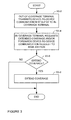
- FIG. 3 is a flow chart showing steps of a method of changing coverage of a base station.
- the method begins with the out-of-coverage terminal transmitting a request to establish a D2D link to the in-coverage terminal (e.g., terminal 208-1) (step S3-2). Such a request can be made, for example, when an out-of-coverage terminal has data to be transmitted or requires a service.
- the in-coverage terminal requests its serving base station (e.g., base station 202) for extended coverage and/or forwards the received D2D request to the base station (step S3-4).
- the base station decides whether or not to extend the coverage (step S3-6) and, if the decision is affirmative, extends the coverage (step S3-8).
- the decision to extend the coverage may be based, for example, on a number of D2D requests exceeding a certain threshold.
- the number of D2D requests may therefore relate to a total number of requests, a total number of requests received from a particular in-coverage terminal (which may indicate that a number of out-of-coverage terminals are located in a particular area), and so on.
- the out-of-coverage and/or in-coverage terminals may provide information such as channel measurements, buffer status, and QoS requirements.
- the coverage may be extended by the use of in-coverage terminals as relay terminals and/or by changing an operating parameter of the base station to extend the coverage within which a direct communication path between the base station and terminal can be established.
- in-coverage terminals as relay terminals will be discussed in more detail later, though it is briefly mentioned that terminals which can support higher throughput are generally more suitable to serve as relay terminals.
- operating parameter refers to any parameter that can be set by the base station in order to affect its coverage, whether hardware, firmware, software, or any combination thereof.
- changing an operating parameter of the base station may include, for example:
- the coverage depicted by a dashed line represents the extended coverage within which a direct communication path between the base station and terminal can be established.
- the extended coverage provided by the use of relay terminals is not depicted.
- the coverage depicted by the solid and dashed lines are shown as omnidirectional coverage, though it will be understood that either or both of the coverage could alternatively be directional, e.g. subdivided into different sectors (sectorized). This means that the coverage of one or more sectors can be selectively extended, for example to provide coverage for a number of out-of-coverage terminals are located in a particular area.
- terminal 208-3 may communicate with base station 202 via a D2D link to (relay) terminal 208-1, while terminal 208-2 becomes a "regular" terminal served by the base station 202 within the extended coverage 205.
- terminal 208-2 may communicate with base station 202 via a D2D link to terminal 208-1.
- embodiments may make use of mechanisms such as advertising and establishing the D2D link. These mechanisms by themselves may be conventional, except as described herein, and are therefore not described in more detail herein except as may be necessary or helpful in understanding the embodiments. (However, one embodiment which will be described in more detail later proposes a design for how D2D-capable devices (which can act as relays for out-of-coverage devices) can advertise this capability, for example by the use of a beacon-like signal.) Further, the skilled person will be aware of how the spectrum (time and frequency) resources may be shared between the D2D links and "regular" (terminal-to-access point) links within a single cell, and no further mention will be made.
- the principles described above can equally be applied to a wireless communication system having a plurality of neighbouring base stations.
- the terms "out-of-coverage terminal” and “in-coverage terminal” are generally defined with respect to one of the base stations, that is whether a terminal is outside of or within the coverage of that base station.
- the base station may be referred to as a "cell-site”
- the coverages of base stations may be referred to as “cells”
- a terminal at the edge of the coverage may be referred to as a "cell-edge terminal”.
- the decision to extend the coverage of a base station may take into account whether changing an operating parameter such as increasing transmission power would result in unacceptable interference to a neighbouring coverage and, if so, whether it is possible to extend the coverage by using an in-coverage terminal as a relay terminal instead.
- terminals served by a lightly-loaded base station are handed off to a neighbouring base station and the lightly-loaded base station is switched off, as described in more detail below.
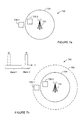
- FIG. 4a schematically shows a wireless cellular communication system 400 comprising a plurality of neighbouring base stations 402-1, 402-2, 402-3, each providing a respective coverage 404-1, 404-2, 404-3.
- three base stations are depicted in this example, it will be appreciated that the wireless communication system may have fewer or more than three base stations.
- the coverages 404-1, 404-2, 404-3 of the base stations 402-1, 402-2, 402-3 may overlap with one another.
- the base station 402-1 is a lightly-loaded base station and that the terminals 408-1, 408-2 are cell-edge terminals representing the vast majority, if not all, of the terminals served by the base station 402-1.
- the coverage of the wireless communication system 400 is changed by switching off the lightly-loaded base station 402-1 and extending the coverage of base stations 402-2, 404-3, to which the terminals 408-1, 408-2 are handed off.
- terminals 408-1, 408-2 report high availability of D2D-capable terminals 408-3, 408-4 within the coverage of the neighbouring base stations 404-2, 404-3 to base station 402-1 (step S5-2). Using these reports as a trigger the base station 402-1 is switched off (step S5-4), and the terminals 408-1, 408-2 handed off to the neighbouring base stations 404-2, 404-3 (step S5-6). The decision to switch off may be based on the number of reports exceeding a threshold. In some embodiments, the terminals 408-3, 408-4 are relied upon to act as relays between terminals 408-1, 408-2 and base stations 402-2, 402-3, respectively.
- the coverage of the base stations 402-2, 402-3 may initially be extended by employing the terminals 408-3, 408-4 as relays, and thereafter one or both of the base stations 402-2, 402-3 may change an operating parameter to allow direct communication with the terminals 408-1, 408-2.
- terminals 408-1, 408-2 may be handed off to neighbouring base stations 404-2, 404-3 before, or substantially at the same time as, the base station 402-1 is switched off.
- steps S5-4 and S5-6 may be exchanged or combined.
- the decision to switch off the lightly-loaded base station 402-1 may involve coordination between the base stations 402-1, 402-2, 402-3.
- the reported information may be shared with the neighbouring base stations 402-2, 402-3, for example using the X2 interface (not shown). This may be used by the neighbouring base stations 402-2, 402-3, possibly in conjunction with additional information, to determine whether to switch off the lightly-loaded base station 402-1 and/or how best to serve the terminals 408-1, 408-2.
- the additional information can include, for example, the transmit power of the terminals 408-1, 408-2, traffic load of the neighbouring base stations 402-2, 402-3, whether frequency resources made available once the light-loaded base station 402-1 is switched off are "better" used for D2D communications or for extending the coverage, as well as whether some terminals are left out of coverage by this switch-off, which may be unacceptable.
- a base station is activated to fill coverage gaps identified by D2D requests made by out-of-coverage terminals.
- FIG. 6a schematically shows a wireless communication system 600 comprising a base station 602-1, with an in-coverage terminal 606-1 that is within the coverage 604-1 of the base station 602 and an out-of-coverage terminal 608-2 that is outside of the coverage 604 of the base station 602.
- the system 600 also comprises a femtocell base station 607.
- the term "wireless communication system” may therefore refer to infrastructure nodes of a plurality, and in some cases different types, of networks available to terminals, such as an eNB of a LTE cellular network and an access point of a WiFi network.
- the manner in which terminals served by different network operators may co-operate, for example by sharing a database to facilitate associating terminals with multiple networks, are not described in more detail herein.
- Terminal 608-2 which could be one of many out-of-coverage terminals, requests D2D communication with terminal 608-1, which similarly could be one of many in-coverage terminals.
- the terminal 608-2 activates femtocell base station 607, for example by instructing or requesting the femtocell base station 607 for radio resources for terminal 608-2.
- a decision to activate the femtocell base station 607 is based on the number of terminals requesting D2D communications that are located within the coverage 609 of the femtocell base station 607 once it is activated, as shown in Figure 6b .
- the coverage 609 may overlap with the coverage 604 of base station 602.
- a change in coverage includes coordinating the usage of radio resources amongst in-coverage and out-of-coverage terminals.
- this can include provisioning a new radio resource to out-of-coverage terminals and/or provisioning an existing radio resource to out-of-coverage terminals.
- An existing radio resource may be a radio resource that is provisioned for use by in-coverage terminals, such as an existing radio resource that is under-used or not used at all.
- the base station 702 when an in-coverage terminal 708-2 receives a D2D request from out-of-coverage terminal 708-1, the base station 702 can be informed accordingly, in a similar manner to that of the embodiment described with reference to Figures 2a and 2b .
- the base station 702 then provisions a radio resource to the out-of-coverage terminal 708-1.
- different radio resources may be provisioned for direct and indirect communications between base station 702 and terminals 708-1, 708-2.
- the coverage of a base station is extended by increasing the transmission bandwidth to serve coverage gaps identified by D2D requests, for example using LTE Advanced (LTE-A) carrier aggregation (CA), a brief description of which follows below.
- LTE-A LTE Advanced
- CA carrier aggregation
- CA increases the overall transmission bandwidth by utilising more than one carrier, and can be used for both frequency division duplex (FDD) and time division duplex (TDD).
- Each aggregated carrier is referred to as a component carrier.
- the component carrier can have a bandwidth of 1.4, 3, 5, 10, 15 or 20 MHz and a maximum of five component carriers can be aggregated. Hence the maximum bandwidth is 100 MHz.
- the number of aggregated carriers can be different in uplink (UL) and downlink (DL), however the number of UL component carriers is never larger than the number of DL component carriers.
- the individual component carriers can also be of different bandwidths.
- One way to arrange aggregation is to use contiguous component carriers within the same operating frequency band (as defined for LTE).
- intra-band contiguous This is referred to as intra-band contiguous.
- Another way to arrange aggregation is to use non-contiguous allocation, which can be either intra-band or it inter-band.
- intra-band the component carriers belong to the same operating frequency band, but are separated by a frequency gap.
- inter-band the component carriers belong to different operating frequency bands.
- the component carriers are referred to as the primary component carrier (PCC) (a downlink primary component carrier and an associated uplink primary component carrier, DL and UL PCC) and the secondary component carrier (SCC) (all other component carriers).
- PCC primary component carrier
- SCC secondary component carrier
- a cell served by the PCC is referred to as a primary service cell
- a cell served by the SCC is referred to as the secondary serving cell.
- the coverage of the primary and secondary serving cells may differ, both due component carrier frequencies but also from power planning.
- different terminals may use different carriers, with the configuration of the primary component carrier being terminal specific and determined according to the loading on the various carriers as well as other relevant parameters.
- the association between the downlink primary carrier and the corresponding uplink primary component carrier is cell specific.
- the coverage 704 defines a primary service cell and the extended coverage 705 defines a secondary service cell.
- Component carriers f1, f2 can be used to communicate with terminal 708-2, whereas terminal 708-1 is not within the coverage of component carrier f1, but is in the coverage of component carrier f2.
- terminal 708-1 can be excluded from using component carrier f1, so that the in-coverage and out-of-coverage terminals 708-1, 708-2 use separate component carriers.
- in-coverage terminals may be employed as relay terminals for out-of-coverage terminals.
- One embodiment provides a mechanism for enabling the in-coverage terminals to advertise their capability to serve as a relay terminal using D2D links.
- in-coverage terminals may use a beacon-like signal, such as a modified UL Sounding Reference Signals (SRS) of LTE-A.
- SRS Modifying UL Sounding Reference Signals
- 3GPP LTE provides two types of uplink reference signals.
- the first type of reference signal is the Demodulation Reference Signal (DM-RS), which is used for channel estimation in the eNB in order to demodulate control and data channels.
- the second type of reference signal is the SRS, which is primarily used to provide uplink channel quality information to enable scheduling decisions in the base station.
- the subframes in which SRSs are transmitted by any UE within a cell are indicated by cell-specific broadcast signalling: a 4-bit cell-specific 'srsSubframeConfiguration' parameter indicates 15 possible sets of subframes in which SRS may be transmitted within each radio frame.
- the SRS can be switched off completely in the cell.
- the SRS transmissions are in the last Single Carrier Frequency Division Multiple Access (SC-FDMA) symbol in the configured subframes.
- the eNB in LTE may either request an individual SRS transmission from a UE or configure a UE to transmit SRS periodically until terminated; a 1-bit UE-specific signalling parameter, 'duration', indicates whether the request SRS transmission is single or periodic.
- the periodicity may be any of 2, 5, 10, 20, 40, 80, 160 or 320 ms; the SRS subframe offset within the period in which the UE should transmit its SRS are configured by a 10-bit UE-specific dedicated signalling parameter called 'srs-ConfigIndex'.
- the above-described SRS signals will be referred to as the "normal" SRS signals.
- such terminals may also send a specially coded SRS every N (configurable) seconds to enable discovery by other terminals.
- the periodicity can be signalled by increasing the number of bits currently used for the srsSubframeConfiguration parameter in order to indicate that this is a special SRS for D2D-capable terminal discovery. It is also possible to keep the normal number of bits for the srsSubframeConfiguration parameter, but in this case it may be necessary to send multiple instances of the srsSubframeConfiguration parameter, e.g. the first instance indicating the periodicity of the normal SRS and the second instance indicating the periodicity of the special SRS.
- the parameter N can be made higher for recently scheduled terminals and/or those terminals whose channel does not vary significantly as the UL channel quality estimation does not need to be carried out frequently in those cases and therefore some SRS slots can be sacrificed for D2D capability advertising.
- This specifically coded SRS need not support high sounding bandwidth as it is not used (solely) for its primary purpose - but in that case the neighbouring devices in search of a D2D partner may need to know which frequencies to scan for this specially coded SRS.
- the bandwidth of the specially coded SRS could change in a frequency hopping manner to increase the changes of being received by a device wishing to establish a D2D connection and/or to spread the chances of discovery across a wide number of devices configured to support relatively narrow and different discovery bandwidths. If these devices however support a wide discovery bandwidth then the sub-band selected for the special SRS could indicate a value of a certain parameter, such as supported throughput on the D2D link, or the QoS that could be offered.
- a terminal that can support higher throughput may be selected if, for example, the terminal exhibits a low buffer level, a high signal-to-noise ratio (SNR), a high battery level, low mobility (i.e. is relatively stationary), or any combination thereof. These may be reported to a base station.
- SNR signal-to-noise ratio
- the modification of SRS is such that the eNB only configures this new SRS for those UEs which can exhibits one or more of these characteristics.
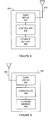
- FIG 8 is a block diagram illustrating an example of a base station 800 in accordance with an embodiment.
- the base station includes transmitter/receiver unit(s) 804 connected to at least one antenna 802 (together defining a communication unit) and a controller 804.
- the controller may be, for example, microprocessor, digital signal processor (DSP), ASIC, FPGA, or other logic circuitry programmed or otherwise configured to perform the various functions described above, such as changing an operating parameter of the base station 800.
- DSP digital signal processor
- ASIC application specific integrated circuitry
- FPGA field-programmable gate array
- FIG. 9 is a block diagram illustrating an example of a terminal 900 in accordance with an embodiment.
- the terminal 900 may include any type of device which may be used in a wireless communication system described above and may include cellular (or cell) phones (including smartphones), personal digital assistants (PDAs) with mobile communication capabilities, laptops or computer systems with mobile communication components, and/or any device that is operable to communicate wirelessly.
- the terminal 900 include transmitter/receiver unit(s) 904 connected to at least one antenna 802 (together defining a communication unit) and a controller 904.
- the controller may be, for example, microprocessor, digital signal processor (DSP), ASIC, FPGA, or other logic circuitry programmed or otherwise configured to perform the various functions described above, such as controlling the communication unit to transmit a SRS signal.
- DSP digital signal processor
- ASIC application specific integrated circuit
- FPGA field-programmable gate array
- Embodiments have been described in which a modified UL Sounding Reference Signals (SRS) of LTE-A is used to advertise a capability of terminal to serve as a relay terminal using D2D links.
- Other UL signalling could alternatively be used, such as a modified Random Access Channel (RACH), where either the first or subsequent messages contain coded information which relates to the indication that apply to that case the neighbouring devices can access this device via a D2D link.
- RACH behaviour could be modified such that, instead of conventional event triggered by RACH, the RACH is sent with a defined repetition frequency.
- a D2D-capable terminal is assigned a dedicated preamble to be used to indicate its D2D/relaying capability. This preamble is transmitted periodically in the Physical Random Access Channel (PRACH).
- PRACH Physical Random Access Channel
- a terminal needing a D2D connection monitors PRACH for the specific dedicated preamble(s) and then in a hand-shaking procedure replies using the same preamble.
- coverage is changed by switching off the base station.
- the base station may be placed on stand-by.
- one or more base station resources including hardware resources and radio resources (e.g. frequency and/or time resource), may be selectively switched off or placed on stand-by.
- Embodiments have been described in which the coverage is changed when an out-of-coverage terminal having data to be transmitted or requires a service. However, in other embodiments, the coverage may be changed when the system has data to transmit to an out-of-coverage terminal. In such embodiments, device-to-device communication between the in-coverage and out-of-coverage terminals can be used to page an out-of-coverage terminal.
- base stations with coverages of various orders of magnitude may be employed, including macrocell base stations, microcell base stations, picocell base stations, femtocell base stations, or any combinations thereof. Examples include, for example, eNBs, Home eNBs and Wi-Fi access points.
- the coverage of the base station may be larger than the coverage of the activated base station, which may be used to fill coverage gaps.
- the base station could be a macrocell base station and the activated base station could be a femtocell base station.
Landscapes
- Engineering & Computer Science (AREA)
- Computer Networks & Wireless Communication (AREA)
- Signal Processing (AREA)
- Mobile Radio Communication Systems (AREA)
Priority Applications (4)
| Application Number | Priority Date | Filing Date | Title |
|---|---|---|---|
| EP13161686.4A EP2785092B1 (fr) | 2013-03-28 | 2013-03-28 | Système de communication sans fil |
| US14/205,701 US9363678B2 (en) | 2013-03-28 | 2014-03-12 | Wireless communication system |
| CN201410102704.XA CN104080097A (zh) | 2013-03-28 | 2014-03-19 | 无线通信系统 |
| JP2014057919A JP2014195249A (ja) | 2013-03-28 | 2014-03-20 | 動作方法、無線通信システム、基地局及び端末 |
Applications Claiming Priority (1)
| Application Number | Priority Date | Filing Date | Title |
|---|---|---|---|
| EP13161686.4A EP2785092B1 (fr) | 2013-03-28 | 2013-03-28 | Système de communication sans fil |
Publications (2)
| Publication Number | Publication Date |
|---|---|
| EP2785092A1 true EP2785092A1 (fr) | 2014-10-01 |
| EP2785092B1 EP2785092B1 (fr) | 2015-09-23 |
Family
ID=47997246
Family Applications (1)
| Application Number | Title | Priority Date | Filing Date |
|---|---|---|---|
| EP13161686.4A Not-in-force EP2785092B1 (fr) | 2013-03-28 | 2013-03-28 | Système de communication sans fil |
Country Status (4)
| Country | Link |
|---|---|
| US (1) | US9363678B2 (fr) |
| EP (1) | EP2785092B1 (fr) |
| JP (1) | JP2014195249A (fr) |
| CN (1) | CN104080097A (fr) |
Cited By (6)
| Publication number | Priority date | Publication date | Assignee | Title |
|---|---|---|---|---|
| WO2016041589A1 (fr) * | 2014-09-17 | 2016-03-24 | Nokia Solutions And Networks Oy | Communications dans un système sans fil |
| WO2016107205A1 (fr) * | 2015-01-04 | 2016-07-07 | 中兴通讯股份有限公司 | Procédé et dispositif pour une transmission de données dans des communications de relais |
| WO2016128213A1 (fr) * | 2015-02-11 | 2016-08-18 | Sony Corporation | Dispositif de communication, équipement d'infrastructure et procédés |
| WO2016187955A1 (fr) * | 2015-05-25 | 2016-12-01 | 宇龙计算机通信科技(深圳)有限公司 | Procédé de gestion de position de terminal, procédé, dispositif et terminal de radiomessagerie |
| EP3220672A4 (fr) * | 2014-11-14 | 2017-11-01 | KDDI Corporation | Dispositif de commande radio, dispositif terminal et procédé de communication |
| EP3282719A4 (fr) * | 2015-04-08 | 2018-03-21 | China Academy of Telecommunications Technology | Procédé et dispositif pour déterminer et utiliser un noeud de relais de dispositif à dispositif (d2d) |
Families Citing this family (34)
| Publication number | Priority date | Publication date | Assignee | Title |
|---|---|---|---|---|
| US9699767B2 (en) * | 2013-09-27 | 2017-07-04 | Kyocera Corporation | Communication control method |
| JP6343672B2 (ja) * | 2013-12-20 | 2018-06-13 | 京セラ株式会社 | 装置間通信リソースの管理 |
| WO2015170898A1 (fr) * | 2014-05-07 | 2015-11-12 | 엘지전자 주식회사 | Procédé exécuté par un terminal pour déterminer une couverture de cellule dans un système de communication sans fil, et terminal utilisant le procédé |
| EP3142433A4 (fr) * | 2014-05-08 | 2017-04-26 | Fujitsu Limited | Systeme de communication sans fil, terminal, station de base et procede de traitement |
| KR102029245B1 (ko) * | 2014-07-31 | 2019-11-08 | 엘지전자 주식회사 | 무선 통신 시스템에서 신호 전송 방법 및 장치 |
| JP2016096475A (ja) * | 2014-11-14 | 2016-05-26 | Kddi株式会社 | 無線制御装置、端末装置、および通信方法 |
| CN107079380A (zh) * | 2014-11-14 | 2017-08-18 | 株式会社Ntt都科摩 | 用户装置及d2d通信方法 |
| CN104486739B (zh) * | 2014-11-20 | 2019-03-22 | 南京酷派软件技术有限公司 | 确定辅助通信终端的方法及系统 |
| DE102014224781B3 (de) * | 2014-12-03 | 2016-04-14 | Robert Bosch Gmbh | Verfahren zur Konfiguration eines Funknetzwerks und Zentralstation für ein Funknetzwerk |
| EP3236596B1 (fr) * | 2014-12-16 | 2020-04-08 | Fujitsu Limited | Procédé et appareil d'estimation de canal de liaison descendante basés sur un signal de référence de sondage, et système de communication |
| CN106211027B (zh) * | 2014-12-25 | 2021-06-18 | 北京三星通信技术研究有限公司 | 一种实现d2d终端时频同步的方法和设备 |
| US9942944B2 (en) * | 2014-12-29 | 2018-04-10 | Intel IP Corporation | Network-initiated discovery and path selection procedures for multi-hop underlay networks |
| WO2016124750A1 (fr) * | 2015-02-06 | 2016-08-11 | Telefonaktiebolaget Lm Ericsson (Publ) | Recherche de cellule adaptative de dispositif à dispositif |
| KR102430341B1 (ko) * | 2015-02-11 | 2022-08-08 | 소니그룹주식회사 | 통신 디바이스, 인프라스트럭처 장비, 이동 통신 네트워크 및 방법들 |
| CN106034340B (zh) * | 2015-03-10 | 2020-12-04 | 中兴通讯股份有限公司 | 一种通信模式的控制方法、基站、用户终端及系统 |
| US9769862B2 (en) * | 2015-04-09 | 2017-09-19 | Sharp Laboratories Of America, Inc. | Method and apparatus for implementing partial coverage and out-of-coverage sidelink discovery resource pools for wireless communications |
| CN106211024A (zh) | 2015-04-10 | 2016-12-07 | 中兴通讯股份有限公司 | 信息处理方法及通信节点 |
| CN106162598B (zh) * | 2015-04-10 | 2019-09-17 | 电信科学技术研究院 | 一种用户设备到网络中继场景下的通信方法及装置 |
| CN107637162B (zh) * | 2015-05-14 | 2022-05-10 | 苹果公司 | Ue到网络中继发起和配置 |
| CN106303915B (zh) * | 2015-06-08 | 2021-05-28 | 索尼公司 | 无线通信设备和无线通信方法 |
| CN105208621A (zh) * | 2015-08-14 | 2015-12-30 | 宇龙计算机通信科技(深圳)有限公司 | 一种通信的方法、终端及基站 |
| US10362559B2 (en) * | 2015-09-07 | 2019-07-23 | Lg Electronics Inc. | Method for supporting device-to-device direct communication in wireless communication system, and apparatus therefor |
| US10524108B2 (en) * | 2015-10-19 | 2019-12-31 | Qualomm Incorporated | D2D communication for eMTC design considerations |
| CN105307234A (zh) * | 2015-11-05 | 2016-02-03 | 东莞酷派软件技术有限公司 | 远端终端的准入控制方法及装置、终端和基站 |
| EP3226472A1 (fr) * | 2016-04-01 | 2017-10-04 | Thomson Licensing | Procédé de prédiction d'un niveau de qualité d'expérience d'une application destinée à être exécutée sur un équipement d'utilisateur sans fil |
| CN107371119A (zh) * | 2016-05-13 | 2017-11-21 | 索尼公司 | 电子装置、信息处理设备和信息处理方法 |
| US10778387B2 (en) * | 2016-11-23 | 2020-09-15 | Huawei Technologies Co., Ltd. | System and method for group-assisted downlink transmission |
| CN110100480B (zh) * | 2017-01-18 | 2020-11-17 | 华为技术有限公司 | 在覆盖范围外区域中保持通信的无线电资源控制器 |
| CN109246774B (zh) | 2017-06-16 | 2021-01-05 | 华为技术有限公司 | 通信方法及装置 |
| KR102380185B1 (ko) * | 2017-09-18 | 2022-03-29 | 삼성전자주식회사 | 무선 통신 시스템에서 빔포밍을 운용하기 위한 장치 및 방법 |
| CN107862856B (zh) * | 2017-09-20 | 2020-05-08 | 华为技术有限公司 | 一种交通信息处理方法及装置 |
| US11716726B2 (en) * | 2020-08-07 | 2023-08-01 | Qualcomm Incorporated | Message handling for device-to-device coordination messages |
| CN112437486A (zh) * | 2020-11-20 | 2021-03-02 | 国网北京市电力公司 | 定位数据传输方法、装置及计算机可读存储介质 |
| CN113115227B (zh) * | 2021-04-21 | 2022-11-01 | 鹏城实验室 | 高空基站防止终端丢失覆盖的处理方法、装置及高空基站 |
Citations (4)
| Publication number | Priority date | Publication date | Assignee | Title |
|---|---|---|---|---|
| EP1729533A1 (fr) * | 2005-05-31 | 2006-12-06 | Samsung Electronics Co.,Ltd. | Procédé d'ordonnancement dans un système de radiocommunication avec des répéteurs, et système correspondant |
| WO2008090049A1 (fr) * | 2007-01-23 | 2008-07-31 | Nokia Siemens Networks Gmbh & Co. Kg | Distribution de charges entre des stations de base par modulation de la puissance de transmission |
| EP2018073A1 (fr) * | 2006-04-29 | 2009-01-21 | Alcatel Lucent | Station relais, station de base et procédé pour étendre une zone de couverture d'une station de base dans un réseau radio |
| US20120157146A1 (en) * | 2010-12-20 | 2012-06-21 | Motorola Solutions, Inc. | Method and apparatus for dynamically enabling a direct mode operation gateway |
Family Cites Families (19)
| Publication number | Priority date | Publication date | Assignee | Title |
|---|---|---|---|---|
| JP3622725B2 (ja) * | 2001-12-28 | 2005-02-23 | 日本電気株式会社 | 移動体通信システム及び移動体無線端末 |
| US7295544B2 (en) * | 2004-07-29 | 2007-11-13 | Motorola, Inc. | Routing protocol within hybrid-cellular networks |
| US20060246887A1 (en) * | 2005-05-02 | 2006-11-02 | Barclay Deborah L | Mapping of weak RF signal areas in a wireless telecommunication system using customers' mobile units |
| US7406060B2 (en) * | 2005-07-06 | 2008-07-29 | Nortel Networks Limited | Coverage improvement in wireless systems with fixed infrastructure based relays |
| CN101541106B (zh) * | 2008-03-17 | 2012-04-18 | 中兴通讯股份有限公司 | 一种无线通信系统中的中继方法 |
| KR101500025B1 (ko) * | 2008-04-21 | 2015-03-06 | 애플 인크. | 무선 중계 프레임 구조, 프로토콜, 및 오퍼레이션을 위한 시스템 및 방법 |
| US9037134B2 (en) * | 2008-06-13 | 2015-05-19 | Qualcomm Incorporated | Mobile devices with femto cell functionality |
| US8493887B2 (en) * | 2008-12-30 | 2013-07-23 | Qualcomm Incorporated | Centralized control of peer discovery pilot transmission |
| US8208891B2 (en) * | 2009-05-01 | 2012-06-26 | At&T Intellectual Property I, L.P. | Methods and systems for relaying out of range emergency information |
| WO2011109941A1 (fr) * | 2010-03-11 | 2011-09-15 | Nokia Corporation | Procédé et appareil pour l'établissement d'une communication de dispositif à dispositif |
| EP2509382A1 (fr) * | 2011-04-08 | 2012-10-10 | Telefonaktiebolaget LM Ericsson (publ) | Programmateur de relais vert |
| CN103650624B (zh) * | 2011-06-02 | 2018-04-24 | 安华高科技通用Ip(新加坡)公司 | 一种用于移动通信系统中的设备到设备通信路由建立的装置和方法 |
| GB2498395B (en) * | 2012-01-16 | 2014-10-08 | Broadcom Corp | A method and apparatus for modifying one or more cell reselection parameters |
| GB2498765A (en) * | 2012-01-27 | 2013-07-31 | Renesas Mobile Corp | Discovery signalling in a device-to-device communication system |
| CN103517371B (zh) * | 2012-06-18 | 2017-09-08 | 中国移动通信集团公司 | 一种设备到设备的通信方法、装置及系统 |
| EP2879414A4 (fr) * | 2012-07-27 | 2016-03-23 | Kyocera Corp | Système de communication mobile, station de base, dispositif utilisateur et processeur |
| US9036603B2 (en) * | 2012-08-03 | 2015-05-19 | Intel Corporation | Network assistance for device-to-device discovery |
| US8902907B2 (en) * | 2012-10-05 | 2014-12-02 | Futurewei Technologies, Inc. | Terminal based grouping virtual transmission and reception in wireless networks |
| US9420511B2 (en) * | 2012-11-01 | 2016-08-16 | Intel Corporation | Signaling QoS requirements and UE power preference in LTE-A networks |
-
2013
- 2013-03-28 EP EP13161686.4A patent/EP2785092B1/fr not_active Not-in-force
-
2014
- 2014-03-12 US US14/205,701 patent/US9363678B2/en not_active Expired - Fee Related
- 2014-03-19 CN CN201410102704.XA patent/CN104080097A/zh active Pending
- 2014-03-20 JP JP2014057919A patent/JP2014195249A/ja active Pending
Patent Citations (4)
| Publication number | Priority date | Publication date | Assignee | Title |
|---|---|---|---|---|
| EP1729533A1 (fr) * | 2005-05-31 | 2006-12-06 | Samsung Electronics Co.,Ltd. | Procédé d'ordonnancement dans un système de radiocommunication avec des répéteurs, et système correspondant |
| EP2018073A1 (fr) * | 2006-04-29 | 2009-01-21 | Alcatel Lucent | Station relais, station de base et procédé pour étendre une zone de couverture d'une station de base dans un réseau radio |
| WO2008090049A1 (fr) * | 2007-01-23 | 2008-07-31 | Nokia Siemens Networks Gmbh & Co. Kg | Distribution de charges entre des stations de base par modulation de la puissance de transmission |
| US20120157146A1 (en) * | 2010-12-20 | 2012-06-21 | Motorola Solutions, Inc. | Method and apparatus for dynamically enabling a direct mode operation gateway |
Cited By (13)
| Publication number | Priority date | Publication date | Assignee | Title |
|---|---|---|---|---|
| WO2016041589A1 (fr) * | 2014-09-17 | 2016-03-24 | Nokia Solutions And Networks Oy | Communications dans un système sans fil |
| US10531446B2 (en) | 2014-11-14 | 2020-01-07 | Kddi Corporation | Radio control device, terminal device, and communication method |
| EP3220672A4 (fr) * | 2014-11-14 | 2017-11-01 | KDDI Corporation | Dispositif de commande radio, dispositif terminal et procédé de communication |
| EP3496434A1 (fr) * | 2014-11-14 | 2019-06-12 | KDDI Corporation | Communication de terminal-à-terminal |
| EP3745751A1 (fr) * | 2014-11-14 | 2020-12-02 | KDDI Corporation | Communication de dispositif-terminal-à-dispositif-terminal impliquant un dispositif terminal de relais |
| WO2016107205A1 (fr) * | 2015-01-04 | 2016-07-07 | 中兴通讯股份有限公司 | Procédé et dispositif pour une transmission de données dans des communications de relais |
| WO2016128213A1 (fr) * | 2015-02-11 | 2016-08-18 | Sony Corporation | Dispositif de communication, équipement d'infrastructure et procédés |
| US10405257B2 (en) | 2015-02-11 | 2019-09-03 | Sony Corporation | Communications device, infrastructure equipment, and methods |
| US11140609B2 (en) | 2015-02-11 | 2021-10-05 | Sony Corporation | Communications device, infrastructure equipment, and methods |
| US11956707B2 (en) | 2015-02-11 | 2024-04-09 | Sony Group Corporation | Communications device, infrastructure equipment, and methods |
| EP3282719A4 (fr) * | 2015-04-08 | 2018-03-21 | China Academy of Telecommunications Technology | Procédé et dispositif pour déterminer et utiliser un noeud de relais de dispositif à dispositif (d2d) |
| US10420009B2 (en) | 2015-04-08 | 2019-09-17 | China Academy Of Telecommunications Technology | Methods and devices for determining and using Device-to-Device relay node |
| WO2016187955A1 (fr) * | 2015-05-25 | 2016-12-01 | 宇龙计算机通信科技(深圳)有限公司 | Procédé de gestion de position de terminal, procédé, dispositif et terminal de radiomessagerie |
Also Published As
| Publication number | Publication date |
|---|---|
| JP2014195249A (ja) | 2014-10-09 |
| US9363678B2 (en) | 2016-06-07 |
| CN104080097A (zh) | 2014-10-01 |
| US20140295827A1 (en) | 2014-10-02 |
| EP2785092B1 (fr) | 2015-09-23 |
Similar Documents
| Publication | Publication Date | Title |
|---|---|---|
| EP2785092B1 (fr) | Système de communication sans fil | |
| US11470611B2 (en) | Communications in a wireless network for carrier selection and switching | |
| KR102929800B1 (ko) | 트리거까지의 시간 및 조건부 핸드오버 향상 기술 | |
| EP2695480B1 (fr) | Agrégation de porteuses opportuniste utilisant des porteuses d'extension à courte portée | |
| EP3243358B1 (fr) | Noeud de réseau, dispositif sans fil et procédés intégrés de sélection d'un mode de communication dans un réseau de communication sans fil | |
| EP3721655B1 (fr) | Procédé de communication, dispositif et support de stockage lisible par ordinateur pour dispositif de relais | |
| CN103686858B (zh) | 上行控制信息的反馈方法、基站及用户设备 | |
| US11044639B2 (en) | Techniques for transmission control protocol aware handover type determination | |
| JP5636132B1 (ja) | 基地局、無線端末、及び方法 | |
| WO2016186742A1 (fr) | Gestion de couche autonome | |
| CN113170496A (zh) | 基于优先级的共存 | |
| JP2014168311A (ja) | 通信制御方法、基地局、及び無線端末 | |
| WO2022056810A1 (fr) | Sélection de cellule d'ancrage à double connectivité multi-rat | |
| CN115299137B (zh) | 在多无线电接入技术双连接中操作用户设备(ue)的功率高效的方式 | |
| US9577777B2 (en) | Method and apparatus for controlling inter-cellular interference in HetNet system | |
| KR102149889B1 (ko) | D2d를 위한 블랭크 서브프레임 사용 |
Legal Events
| Date | Code | Title | Description |
|---|---|---|---|
| 17P | Request for examination filed |
Effective date: 20140212 |
|
| AK | Designated contracting states |
Kind code of ref document: A1 Designated state(s): AL AT BE BG CH CY CZ DE DK EE ES FI FR GB GR HR HU IE IS IT LI LT LU LV MC MK MT NL NO PL PT RO RS SE SI SK SM TR |
|
| AX | Request for extension of the european patent |
Extension state: BA ME |
|
| PUAI | Public reference made under article 153(3) epc to a published international application that has entered the european phase |
Free format text: ORIGINAL CODE: 0009012 |
|
| GRAP | Despatch of communication of intention to grant a patent |
Free format text: ORIGINAL CODE: EPIDOSNIGR1 |
|
| RIC1 | Information provided on ipc code assigned before grant |
Ipc: H04W 16/00 20090101ALI20150326BHEP Ipc: H04W 16/08 20090101AFI20150326BHEP Ipc: H04W 88/04 20090101ALI20150326BHEP |
|
| INTG | Intention to grant announced |
Effective date: 20150416 |
|
| GRAS | Grant fee paid |
Free format text: ORIGINAL CODE: EPIDOSNIGR3 |
|
| GRAA | (expected) grant |
Free format text: ORIGINAL CODE: 0009210 |
|
| AK | Designated contracting states |
Kind code of ref document: B1 Designated state(s): AL AT BE BG CH CY CZ DE DK EE ES FI FR GB GR HR HU IE IS IT LI LT LU LV MC MK MT NL NO PL PT RO RS SE SI SK SM TR |
|
| REG | Reference to a national code |
Ref country code: GB Ref legal event code: FG4D |
|
| REG | Reference to a national code |
Ref country code: CH Ref legal event code: EP |
|
| REG | Reference to a national code |
Ref country code: AT Ref legal event code: REF Ref document number: 751789 Country of ref document: AT Kind code of ref document: T Effective date: 20151015 |
|
| REG | Reference to a national code |
Ref country code: IE Ref legal event code: FG4D |
|
| REG | Reference to a national code |
Ref country code: DE Ref legal event code: R096 Ref document number: 602013003181 Country of ref document: DE |
|
| REG | Reference to a national code |
Ref country code: NL Ref legal event code: MP Effective date: 20150923 |
|
| PG25 | Lapsed in a contracting state [announced via postgrant information from national office to epo] |
Ref country code: LT Free format text: LAPSE BECAUSE OF FAILURE TO SUBMIT A TRANSLATION OF THE DESCRIPTION OR TO PAY THE FEE WITHIN THE PRESCRIBED TIME-LIMIT Effective date: 20150923 Ref country code: FI Free format text: LAPSE BECAUSE OF FAILURE TO SUBMIT A TRANSLATION OF THE DESCRIPTION OR TO PAY THE FEE WITHIN THE PRESCRIBED TIME-LIMIT Effective date: 20150923 Ref country code: NO Free format text: LAPSE BECAUSE OF FAILURE TO SUBMIT A TRANSLATION OF THE DESCRIPTION OR TO PAY THE FEE WITHIN THE PRESCRIBED TIME-LIMIT Effective date: 20151223 Ref country code: LV Free format text: LAPSE BECAUSE OF FAILURE TO SUBMIT A TRANSLATION OF THE DESCRIPTION OR TO PAY THE FEE WITHIN THE PRESCRIBED TIME-LIMIT Effective date: 20150923 Ref country code: GR Free format text: LAPSE BECAUSE OF FAILURE TO SUBMIT A TRANSLATION OF THE DESCRIPTION OR TO PAY THE FEE WITHIN THE PRESCRIBED TIME-LIMIT Effective date: 20151224 |
|
| REG | Reference to a national code |
Ref country code: LT Ref legal event code: MG4D Ref country code: FR Ref legal event code: PLFP Year of fee payment: 4 |
|
| REG | Reference to a national code |
Ref country code: AT Ref legal event code: MK05 Ref document number: 751789 Country of ref document: AT Kind code of ref document: T Effective date: 20150923 |
|
| PG25 | Lapsed in a contracting state [announced via postgrant information from national office to epo] |
Ref country code: SE Free format text: LAPSE BECAUSE OF FAILURE TO SUBMIT A TRANSLATION OF THE DESCRIPTION OR TO PAY THE FEE WITHIN THE PRESCRIBED TIME-LIMIT Effective date: 20150923 Ref country code: HR Free format text: LAPSE BECAUSE OF FAILURE TO SUBMIT A TRANSLATION OF THE DESCRIPTION OR TO PAY THE FEE WITHIN THE PRESCRIBED TIME-LIMIT Effective date: 20150923 Ref country code: RS Free format text: LAPSE BECAUSE OF FAILURE TO SUBMIT A TRANSLATION OF THE DESCRIPTION OR TO PAY THE FEE WITHIN THE PRESCRIBED TIME-LIMIT Effective date: 20150923 |
|
| PG25 | Lapsed in a contracting state [announced via postgrant information from national office to epo] |
Ref country code: NL Free format text: LAPSE BECAUSE OF FAILURE TO SUBMIT A TRANSLATION OF THE DESCRIPTION OR TO PAY THE FEE WITHIN THE PRESCRIBED TIME-LIMIT Effective date: 20150923 |
|
| PG25 | Lapsed in a contracting state [announced via postgrant information from national office to epo] |
Ref country code: SK Free format text: LAPSE BECAUSE OF FAILURE TO SUBMIT A TRANSLATION OF THE DESCRIPTION OR TO PAY THE FEE WITHIN THE PRESCRIBED TIME-LIMIT Effective date: 20150923 Ref country code: IT Free format text: LAPSE BECAUSE OF FAILURE TO SUBMIT A TRANSLATION OF THE DESCRIPTION OR TO PAY THE FEE WITHIN THE PRESCRIBED TIME-LIMIT Effective date: 20150923 Ref country code: ES Free format text: LAPSE BECAUSE OF FAILURE TO SUBMIT A TRANSLATION OF THE DESCRIPTION OR TO PAY THE FEE WITHIN THE PRESCRIBED TIME-LIMIT Effective date: 20150923 Ref country code: EE Free format text: LAPSE BECAUSE OF FAILURE TO SUBMIT A TRANSLATION OF THE DESCRIPTION OR TO PAY THE FEE WITHIN THE PRESCRIBED TIME-LIMIT Effective date: 20150923 Ref country code: CZ Free format text: LAPSE BECAUSE OF FAILURE TO SUBMIT A TRANSLATION OF THE DESCRIPTION OR TO PAY THE FEE WITHIN THE PRESCRIBED TIME-LIMIT Effective date: 20150923 Ref country code: IS Free format text: LAPSE BECAUSE OF FAILURE TO SUBMIT A TRANSLATION OF THE DESCRIPTION OR TO PAY THE FEE WITHIN THE PRESCRIBED TIME-LIMIT Effective date: 20160123 |
|
| PG25 | Lapsed in a contracting state [announced via postgrant information from national office to epo] |
Ref country code: AT Free format text: LAPSE BECAUSE OF FAILURE TO SUBMIT A TRANSLATION OF THE DESCRIPTION OR TO PAY THE FEE WITHIN THE PRESCRIBED TIME-LIMIT Effective date: 20150923 Ref country code: PL Free format text: LAPSE BECAUSE OF FAILURE TO SUBMIT A TRANSLATION OF THE DESCRIPTION OR TO PAY THE FEE WITHIN THE PRESCRIBED TIME-LIMIT Effective date: 20150923 Ref country code: RO Free format text: LAPSE BECAUSE OF FAILURE TO SUBMIT A TRANSLATION OF THE DESCRIPTION OR TO PAY THE FEE WITHIN THE PRESCRIBED TIME-LIMIT Effective date: 20150923 Ref country code: PT Free format text: LAPSE BECAUSE OF FAILURE TO SUBMIT A TRANSLATION OF THE DESCRIPTION OR TO PAY THE FEE WITHIN THE PRESCRIBED TIME-LIMIT Effective date: 20160125 |
|
| REG | Reference to a national code |
Ref country code: DE Ref legal event code: R097 Ref document number: 602013003181 Country of ref document: DE |
|
| PLBE | No opposition filed within time limit |
Free format text: ORIGINAL CODE: 0009261 |
|
| STAA | Information on the status of an ep patent application or granted ep patent |
Free format text: STATUS: NO OPPOSITION FILED WITHIN TIME LIMIT |
|
| 26N | No opposition filed |
Effective date: 20160624 |
|
| PG25 | Lapsed in a contracting state [announced via postgrant information from national office to epo] |
Ref country code: BE Free format text: LAPSE BECAUSE OF NON-PAYMENT OF DUE FEES Effective date: 20160331 Ref country code: DK Free format text: LAPSE BECAUSE OF FAILURE TO SUBMIT A TRANSLATION OF THE DESCRIPTION OR TO PAY THE FEE WITHIN THE PRESCRIBED TIME-LIMIT Effective date: 20150923 |
|
| PG25 | Lapsed in a contracting state [announced via postgrant information from national office to epo] |
Ref country code: MC Free format text: LAPSE BECAUSE OF FAILURE TO SUBMIT A TRANSLATION OF THE DESCRIPTION OR TO PAY THE FEE WITHIN THE PRESCRIBED TIME-LIMIT Effective date: 20150923 Ref country code: LU Free format text: LAPSE BECAUSE OF FAILURE TO SUBMIT A TRANSLATION OF THE DESCRIPTION OR TO PAY THE FEE WITHIN THE PRESCRIBED TIME-LIMIT Effective date: 20160328 |
|
| REG | Reference to a national code |
Ref country code: CH Ref legal event code: PL |
|
| PG25 | Lapsed in a contracting state [announced via postgrant information from national office to epo] |
Ref country code: SI Free format text: LAPSE BECAUSE OF FAILURE TO SUBMIT A TRANSLATION OF THE DESCRIPTION OR TO PAY THE FEE WITHIN THE PRESCRIBED TIME-LIMIT Effective date: 20150923 |
|
| REG | Reference to a national code |
Ref country code: IE Ref legal event code: MM4A |
|
| PG25 | Lapsed in a contracting state [announced via postgrant information from national office to epo] |
Ref country code: BE Free format text: LAPSE BECAUSE OF FAILURE TO SUBMIT A TRANSLATION OF THE DESCRIPTION OR TO PAY THE FEE WITHIN THE PRESCRIBED TIME-LIMIT Effective date: 20150923 |
|
| PG25 | Lapsed in a contracting state [announced via postgrant information from national office to epo] |
Ref country code: CH Free format text: LAPSE BECAUSE OF NON-PAYMENT OF DUE FEES Effective date: 20160331 Ref country code: LI Free format text: LAPSE BECAUSE OF NON-PAYMENT OF DUE FEES Effective date: 20160331 Ref country code: IE Free format text: LAPSE BECAUSE OF NON-PAYMENT OF DUE FEES Effective date: 20160328 |
|
| REG | Reference to a national code |
Ref country code: FR Ref legal event code: PLFP Year of fee payment: 5 |
|
| PGFP | Annual fee paid to national office [announced via postgrant information from national office to epo] |
Ref country code: DE Payment date: 20170321 Year of fee payment: 5 Ref country code: FR Payment date: 20170213 Year of fee payment: 5 |
|
| PGFP | Annual fee paid to national office [announced via postgrant information from national office to epo] |
Ref country code: GB Payment date: 20170104 Year of fee payment: 5 |
|
| PG25 | Lapsed in a contracting state [announced via postgrant information from national office to epo] |
Ref country code: MT Free format text: LAPSE BECAUSE OF FAILURE TO SUBMIT A TRANSLATION OF THE DESCRIPTION OR TO PAY THE FEE WITHIN THE PRESCRIBED TIME-LIMIT Effective date: 20150923 |
|
| PG25 | Lapsed in a contracting state [announced via postgrant information from national office to epo] |
Ref country code: HU Free format text: LAPSE BECAUSE OF FAILURE TO SUBMIT A TRANSLATION OF THE DESCRIPTION OR TO PAY THE FEE WITHIN THE PRESCRIBED TIME-LIMIT; INVALID AB INITIO Effective date: 20130328 Ref country code: SM Free format text: LAPSE BECAUSE OF FAILURE TO SUBMIT A TRANSLATION OF THE DESCRIPTION OR TO PAY THE FEE WITHIN THE PRESCRIBED TIME-LIMIT Effective date: 20150923 |
|
| PG25 | Lapsed in a contracting state [announced via postgrant information from national office to epo] |
Ref country code: MT Free format text: LAPSE BECAUSE OF FAILURE TO SUBMIT A TRANSLATION OF THE DESCRIPTION OR TO PAY THE FEE WITHIN THE PRESCRIBED TIME-LIMIT Effective date: 20160331 Ref country code: MK Free format text: LAPSE BECAUSE OF FAILURE TO SUBMIT A TRANSLATION OF THE DESCRIPTION OR TO PAY THE FEE WITHIN THE PRESCRIBED TIME-LIMIT Effective date: 20150923 Ref country code: TR Free format text: LAPSE BECAUSE OF FAILURE TO SUBMIT A TRANSLATION OF THE DESCRIPTION OR TO PAY THE FEE WITHIN THE PRESCRIBED TIME-LIMIT Effective date: 20150923 Ref country code: CY Free format text: LAPSE BECAUSE OF FAILURE TO SUBMIT A TRANSLATION OF THE DESCRIPTION OR TO PAY THE FEE WITHIN THE PRESCRIBED TIME-LIMIT Effective date: 20150923 |
|
| PG25 | Lapsed in a contracting state [announced via postgrant information from national office to epo] |
Ref country code: BG Free format text: LAPSE BECAUSE OF FAILURE TO SUBMIT A TRANSLATION OF THE DESCRIPTION OR TO PAY THE FEE WITHIN THE PRESCRIBED TIME-LIMIT Effective date: 20150923 |
|
| REG | Reference to a national code |
Ref country code: DE Ref legal event code: R119 Ref document number: 602013003181 Country of ref document: DE |
|
| PG25 | Lapsed in a contracting state [announced via postgrant information from national office to epo] |
Ref country code: AL Free format text: LAPSE BECAUSE OF FAILURE TO SUBMIT A TRANSLATION OF THE DESCRIPTION OR TO PAY THE FEE WITHIN THE PRESCRIBED TIME-LIMIT Effective date: 20150923 |
|
| GBPC | Gb: european patent ceased through non-payment of renewal fee |
Effective date: 20180328 |
|
| PG25 | Lapsed in a contracting state [announced via postgrant information from national office to epo] |
Ref country code: DE Free format text: LAPSE BECAUSE OF NON-PAYMENT OF DUE FEES Effective date: 20181002 |
|
| PG25 | Lapsed in a contracting state [announced via postgrant information from national office to epo] |
Ref country code: GB Free format text: LAPSE BECAUSE OF NON-PAYMENT OF DUE FEES Effective date: 20180328 |
|
| PG25 | Lapsed in a contracting state [announced via postgrant information from national office to epo] |
Ref country code: FR Free format text: LAPSE BECAUSE OF NON-PAYMENT OF DUE FEES Effective date: 20180331 |