EP2785287B1 - Dispositif et système de prothèse - Google Patents
Dispositif et système de prothèse Download PDFInfo
- Publication number
- EP2785287B1 EP2785287B1 EP12797712.2A EP12797712A EP2785287B1 EP 2785287 B1 EP2785287 B1 EP 2785287B1 EP 12797712 A EP12797712 A EP 12797712A EP 2785287 B1 EP2785287 B1 EP 2785287B1
- Authority
- EP
- European Patent Office
- Prior art keywords
- valve
- prosthesis
- pump
- pump housing
- channel
- Prior art date
- Legal status (The legal status is an assumption and is not a legal conclusion. Google has not performed a legal analysis and makes no representation as to the accuracy of the status listed.)
- Active
Links
Images








Classifications
-
- A—HUMAN NECESSITIES
- A61—MEDICAL OR VETERINARY SCIENCE; HYGIENE
- A61F—FILTERS IMPLANTABLE INTO BLOOD VESSELS; PROSTHESES; DEVICES PROVIDING PATENCY TO, OR PREVENTING COLLAPSING OF, TUBULAR STRUCTURES OF THE BODY, e.g. STENTS; ORTHOPAEDIC, NURSING OR CONTRACEPTIVE DEVICES; FOMENTATION; TREATMENT OR PROTECTION OF EYES OR EARS; BANDAGES, DRESSINGS OR ABSORBENT PADS; FIRST-AID KITS
- A61F2/00—Filters implantable into blood vessels; Prostheses, i.e. artificial substitutes or replacements for parts of the body; Appliances for connecting them with the body; Devices providing patency to, or preventing collapsing of, tubular structures of the body, e.g. stents
- A61F2/50—Prostheses not implantable in the body
- A61F2/78—Means for protecting prostheses or for attaching them to the body, e.g. bandages, harnesses, straps, or stockings for the limb stump
- A61F2/80—Sockets, e.g. of suction type
-
- A—HUMAN NECESSITIES
- A61—MEDICAL OR VETERINARY SCIENCE; HYGIENE
- A61F—FILTERS IMPLANTABLE INTO BLOOD VESSELS; PROSTHESES; DEVICES PROVIDING PATENCY TO, OR PREVENTING COLLAPSING OF, TUBULAR STRUCTURES OF THE BODY, e.g. STENTS; ORTHOPAEDIC, NURSING OR CONTRACEPTIVE DEVICES; FOMENTATION; TREATMENT OR PROTECTION OF EYES OR EARS; BANDAGES, DRESSINGS OR ABSORBENT PADS; FIRST-AID KITS
- A61F2/00—Filters implantable into blood vessels; Prostheses, i.e. artificial substitutes or replacements for parts of the body; Appliances for connecting them with the body; Devices providing patency to, or preventing collapsing of, tubular structures of the body, e.g. stents
- A61F2/50—Prostheses not implantable in the body
- A61F2/68—Operating or control means
- A61F2/74—Operating or control means fluid, i.e. hydraulic or pneumatic
- A61F2/748—Valve systems
-
- A—HUMAN NECESSITIES
- A61—MEDICAL OR VETERINARY SCIENCE; HYGIENE
- A61F—FILTERS IMPLANTABLE INTO BLOOD VESSELS; PROSTHESES; DEVICES PROVIDING PATENCY TO, OR PREVENTING COLLAPSING OF, TUBULAR STRUCTURES OF THE BODY, e.g. STENTS; ORTHOPAEDIC, NURSING OR CONTRACEPTIVE DEVICES; FOMENTATION; TREATMENT OR PROTECTION OF EYES OR EARS; BANDAGES, DRESSINGS OR ABSORBENT PADS; FIRST-AID KITS
- A61F2/00—Filters implantable into blood vessels; Prostheses, i.e. artificial substitutes or replacements for parts of the body; Appliances for connecting them with the body; Devices providing patency to, or preventing collapsing of, tubular structures of the body, e.g. stents
- A61F2/50—Prostheses not implantable in the body
- A61F2/78—Means for protecting prostheses or for attaching them to the body, e.g. bandages, harnesses, straps, or stockings for the limb stump
- A61F2/80—Sockets, e.g. of suction type
- A61F2002/802—Suction sockets, i.e. utilizing differential air pressure to retain the prosthesis on the stump
-
- A—HUMAN NECESSITIES
- A61—MEDICAL OR VETERINARY SCIENCE; HYGIENE
- A61F—FILTERS IMPLANTABLE INTO BLOOD VESSELS; PROSTHESES; DEVICES PROVIDING PATENCY TO, OR PREVENTING COLLAPSING OF, TUBULAR STRUCTURES OF THE BODY, e.g. STENTS; ORTHOPAEDIC, NURSING OR CONTRACEPTIVE DEVICES; FOMENTATION; TREATMENT OR PROTECTION OF EYES OR EARS; BANDAGES, DRESSINGS OR ABSORBENT PADS; FIRST-AID KITS
- A61F2/00—Filters implantable into blood vessels; Prostheses, i.e. artificial substitutes or replacements for parts of the body; Appliances for connecting them with the body; Devices providing patency to, or preventing collapsing of, tubular structures of the body, e.g. stents
- A61F2/50—Prostheses not implantable in the body
- A61F2/78—Means for protecting prostheses or for attaching them to the body, e.g. bandages, harnesses, straps, or stockings for the limb stump
- A61F2/80—Sockets, e.g. of suction type
- A61F2002/802—Suction sockets, i.e. utilizing differential air pressure to retain the prosthesis on the stump
- A61F2002/805—Suction sockets, i.e. utilizing differential air pressure to retain the prosthesis on the stump having an air valve
Definitions
- the invention relates to a device for connecting a pump to a through hole provided in a prosthesis shaft, the device having at least one channel with a first outlet for connection to the outlet opening provided in the prosthesis socket and a second outlet connectable to the pump, and at least includes a valve.
- Such a device is for example from the US 5,702,489 A or the US 2004/0260403 A1 , which represents the closest prior art, known.
- a negative pressure is often created between the amputee stump, or a liner drawn over it, such as an elastomer, and the prosthetic stem.
- an interior volume is created, which is to be evacuated.
- the prosthesis socket usually has a distal through-bore, to which a vacuum pump is connected.
- a vacuum pump is connected.
- the vacuum pump together with a dedicated power supply is part of the prosthesis structure.
- a switch is arranged on the prosthesis structure itself, by means of which the vacuum pump can be activated, so that the wearer of the prosthesis system can set the subpressure which is comfortable for him and which is necessary for the firm seat of the prosthesis system.
- the advantage of in the WO 2006/135851 A2 provided embodiment is that the support of the prosthesis system always carries the vacuum pump with it, since it is part of the prosthesis system. If the adhesive effect of the prosthetic system is reduced due to the ingress of air, the wearer can simply activate the vacuum pump via the switch and thus restore the optimal pressure. If the pressure is measured by a sensor, the pump can also be activated automatically become.
- an adapter element is arranged between the prosthesis socket and the rest of the prosthesis structure.
- This has a channel whose one output is connected to the through hole provided in the prosthesis socket.
- a connecting device is provided, to which, for example, the pump is connected.
- a needle valve is provided, through which the channel can be closed when no pump is connected to the second output.
- the disadvantage of this system is that the wearer of the prosthesis system can compensate for any loss of pressure between the liner and the prosthesis stem only when carrying a vacuum pump as a separate tool. In addition, he must then connect this vacuum pump to the corresponding device of the prosthetic system or the adapter element, which is difficult to impossible, especially for older or in their mobility limited support of prosthesis systems.
- the valve which closes the second output of the channel when no pump is connected, even without a connected vacuum pump can be opened. In this case, air enters through the channel the internal volume, so that the prosthesis no longer adheres to the amputation stump.
- the invention is thus based on the object to provide a device and a prosthesis system which overcomes the aforementioned disadvantages of the prior art.
- the invention solves this problem by a generic device in which the valve in a first mode and in a second mode can be brought, wherein the valve in the first module, a one-way valve, the only one flow from the first output to allows the second output, and in the second mode is a two-way valve, so that air can flow in both directions through the channel, wherein in each case the valve is flowed through.
- a device can be integrated in a part of a prosthesis system, for example the prosthesis socket, or be designed as a separate component. This is then as an adapter element, for example, between the
- the first exit of the at least one channel can be connected either directly to a part of the prosthesis socket or via a connecting element, for example a hose, to the through hole in the prosthesis socket.
- a pump can be attached to this device.
- the pump is connected to the second output of the at least one channel of the device.
- the valve is already brought into the second mode. In the second mode, the valve is a two-way valve so that air can flow through the channel in both directions. If a prosthesis system in which such a device is used is then applied by the carrier, a vacuum pump can be arranged at the second channel outlet of the device, whereby the internal volume between prosthesis shaft and liner or amputation stump can be evacuated.
- an overpressure pump can be connected to the second channel outlet of the device.
- the valve is in the second mode, ie if it is a two-way valve, air can also be pumped into the internal volume between the prosthesis socket and the liner or amputation stump so that the prosthesis socket and thus the prosthesis system can easily be replaced by the Have the amputation stump released.
- the valve is advantageously in the first mode.
- the valve is a one-way valve which, in a particularly preferred embodiment, allows only flow in the direction from the first outlet to the second outlet of the canal. In this case, it is only possible that air pushed out of the inner volume without being able to get air from outside.
- the valve comprises a membrane.
- the valve may be formed, for example, as a beak or Domventil and with single or double slotting.
- the valve can then be brought from the first mode into the second mode, in that the membrane is pierced, for example, by a piercing element, which in a particularly preferred embodiment comprises a passage, or opened by pressure applied to the membrane. If the piercing element is removed again, the membrane closes and the valve is operated again in the first mode as a one-way valve.
- the at least one channel also has a third output for connection to the through hole provided in the prosthesis socket and a closing element which is connectable to the third output and prevents in a connected state an inflow through the third outlet into the at least one channel.
- the device is flexible.
- the first output for example, on a side facing the prosthesis stem be provided to the device, and so be directly connectable to a part of the prosthesis stem.
- the third output of the at least one channel may in this case be arranged on another side of the device.
- a connecting element for example a hose, can be arranged, with which the third outlet of the at least one channel can be connected to the through hole in the prosthesis shaft. This is particularly advantageous in the event that the through hole provided in the prosthesis socket is not arranged at a position which faces the device in the connected state.
- the device is flexible in this way for a variety of designs of prosthetic stems used.
- the closing element which is connectable to the third output and prevents in this state, an inflow, it is ensured that even in the case that the first output is connected to the through hole in the prosthesis socket, a vacuum within the prosthesis socket between prosthesis stem and amputation stump of Patients can be generated without additional air flows through the third output of the at least one channel.
- the closing element has a one-way valve which, in the connected state of the closing element with the third outlet, only permits outflow through the third outlet from the at least one channel.
- a device according to an embodiment of the present invention need only be designed so that it can connect a through hole provided in a prosthesis shaft with a pump. If it is designed as an adapter element, the device can therefore also be used in conventional prosthesis systems according to the prior art, which are thus easy to retrofit.
- a system is provided with an adapter element of the type described above and a pump with a pump housing, wherein on the pump housing and on the adapter element mutually corresponding connecting means are formed, through which the adapter element with the pump housing can be connected.
- these connecting means may be particularly preferably formed, for example, as at least one groove and at least one spring corresponding to the groove.
- the groove or the spring on the adapter element and the respective other connection means are arranged on the pump housing.
- the adapter element and the pump housing can be simply pushed into one another, so that it comes here to a secure connection.
- this type of attachment of the pump to the device is also advantageous if the device is not designed as a separate adapter element, but integrated into another component of the prosthesis system is.
- the connecting means preferably comprise a connecting plate provided on the device.
- This is for example provided with elements into which the pump housing can snap or snap.
- a separate fastening element can also be provided, which can be fastened to the connecting plate if required. At this fastener then the pump is fastened.
- This embodiment has the advantage that any projections arranged on the connection plate, which may be necessary for the arrangement of the pump directly on the connection plate, no longer have to be present and therefore can no longer accidentally be broken off or otherwise damaged by the wearer of the prosthesis system ,
- the pump can also be inextricably connected, for example, to the connection plate, for example, laminated to this.
- the connecting plate may be attached to the device, for example by snap or locking element or by a screw connection.
- an outwardly projecting pin is arranged on the pump housing, which pin is designed such that it penetrates the membrane when the pump housing is connected to the device. So now if the pump housing connected to the device, the pin penetrates into the second output of the channel of the device. He pierces the membrane, which has the arranged behind the second outlet valve. In this way, the valve is brought from the first mode to the second mode, so that now the pump can both suck air through the at least one channel of the device and pump through it.
- the pin is designed so that it presses on the outer surfaces of the formed as a beak or dome membrane, thus opening the membrane. The pressure is preferably in Applied edge regions of the membrane, so that in the central region in which a slit is provided, an opening results.
- a force application element is preferably arranged both on the pump housing and on the device, by which a force is caused when the pump housing is connected to the device. This force is directed opposite to the release of the pump housing from the device.
- magnetic elements may be provided, which are poled unretenamig and thus attract each other. Accidental release of the pump housing from the device during the pumping process is thus at least more difficult.
- latching and / or snap elements may be provided by which accidental release of the pump housing is further complicated.
- At least one insertion hole is arranged both on the pump housing and on the device, which are aligned with each other in the connected state, so that a plug element can be guided through the insertion holes.
- a further connection which may be formed in particular form-fitting, achieved between the device and the pump housing, is achieved by the one hand, that the device and the pump housing are arranged in an optimal positioning relative to each other, and on the other hand for the Users of a corresponding prosthesis system is easy to solve.
- the plug-in element is designed for example in the form of a socket wrench, which can be used for loosening or tightening screws on the prosthesis system.
- a prosthesis system comprises a prosthesis shaft, a device and a prosthesis structure.
- a pump with a pump housing described above.
- the valve on the device acts in the first mode as a passive discharge valve through which undesirably located in the inner volume of air can be ejected, while it serves as the access of each pump arranged to the inner volume in the second mode. Due to the advantageous embodiment of the pump housing so that it can be connected directly to the device, it is no longer necessary, unlike the prior art, to provide a separate tube which connects the prosthesis system or the device to a separate pump. As a result, both the expenditure on equipment is reduced and the connection of the pump to the prosthesis system or to the device is simplified.
- the valve can also be brought from the first mode into the second mode and vice versa by means of, for example, a manually actuatable switch or another arrangement.
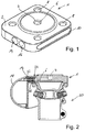
- FIG. 1 shows the schematic view of a device according to a first embodiment of the present invention, wherein the device in the form of an adapter element 1 is formed.
- the device in the form of an adapter element 1
- the statements also apply to other embodiments of a device according to an embodiment of the present invention.
- the adapter element 1 has an upper side 2, on which a prosthesis shaft can be arranged, which in FIG. 1 not shown.
- the top 2 has a first exit 4 of at least one channel 6.
- This first output 4 can be connected to an outlet opening provided on the prosthesis shaft (not shown).
- a plurality of bores 8 through which connecting elements can be guided with which the adapter element 1 can be fastened to the prosthesis shaft.
- On a side surface of the adapter element 1 has a groove 10. At the side surface opposite this side surface, the in the in FIG. 1 is not shown, there is an identical groove 10. These two grooves are part of connecting means 12, through which the adapter element 1 with a pump housing 18, the in FIG. 1 not shown, is connectable.
- FIG. 1 a second output 14 of the channel 6 can be seen.
- an in FIG. 1 connectable pump not shown, can be pumped out through the air from an inner volume, which is formed between a prosthesis stem and a liner or an amputation stump. Since the valve located in the interior of the adapter element 1 is operated in this case in the second mode, air can also be pumped into this internal volume.
- a first force application element 16 is shown, which may be formed, for example, in the form of a magnet.
- FIG. 2 shows a section through a part of a prosthetic system in a schematic representation. It can be seen the adapter element 1 with the channel 6, the first output 4 and the second output 14. At the second output 14, a pump with a pump housing 18 is arranged. In FIG. 2 Below the adapter element 1 is a prosthesis assembly 20, which will not be discussed further here.
- a pin 22 is provided which penetrates when connecting the adapter element 1 with the pump housing 18 in the output 14 of the channel 6.
- a valve 24 which has a membrane 26 which is pierced by the pin 22. This will be with reference to FIG. 6 be explained in more detail.
- FIGS. 3 and 4 It is shown how an adapter element 1 is connected to the pump housing 18. It shows FIG. 3 a schematic View from diagonally down while FIG. 4 shows a schematic view obliquely from above.
- spring elements 28 are provided, which engage in the grooves 10 provided for this purpose on the adapter element 1. Grooves 10 and spring elements 28 together form the connecting means 12. In this way, a particularly simple connection between the adapter element 1 and the pump housing 18 is possible and also accidental removal of the pump housing 18 during the pumping process is significantly more difficult.
- pin 22 In a side wall of the pump housing 18 is the pin 22. As in FIG. 4 can be clearly seen, penetrates this pin 22 in the second output 14 of the channel 6, where he a in the FIGS. 3 and 4 Not shown membrane 26 of the valve 24 pierces and brings the valve so from the first to the second mode.
- pin 22 may provide an opening for the membrane in some other way.
- Both the adapter element 1 and the pump housing 18 each have a force application element 16 is provided, which are both formed in this case as magnetic elements.
- the two force application elements 16 are arranged close to each other or even in contact with each other. Since the two force application elements 16 are magnet elements of different polarity, the two attract, so that they apply a force which is opposite to a detachment of the adapter element 1 from the pump housing 18. In this way, an accidental removal, for example, during the pumping process further difficult.
- FIG. 5 shows a schematic sectional view through an adapter element 1, while the valve 24, the in FIG. 5 circled, is in first mode.
- the adapter element 1 has the channel 6 of the in FIG. 5 upwardly directed first exit 4 and the in FIG. 5 to the left-handed output 14 has.
- a sealing ring 30 is arranged, by which a connection of the adapter element 1 is to be secured to the prosthesis socket to be arranged at this point.
- the valve 24 has the membrane 26 in the in FIG. 5 embodiment shown is formed dome-shaped. In this mode, the valve 24 is a one-way valve. A flow through the valve 24 is possible only in one direction from the first output 4 to the second output 14 of the channel 6.
- the membrane 26 has, for example, a slit which allows such a passage.
- This embodiment has several advantages. On the one hand, it is not possible to inadvertently open the valve 24 in such a way that air flows through the channel 6 in the direction of the first outlet 4. If the adapter element 1 is arranged on a prosthesis shaft in this state, in which the valve 24 is in the first mode, it is ensured that the internal volume which is located between the prosthesis socket and the liner or amputation stump can not be filled with air. If, due to movements or leaks, air enters this internal volume, the internal volume is compressed when the prosthesis is loaded. The air contained therein can penetrate through the first output 4 in the channel 6 and leave the adapter element 1 again by acting as a one-way valve valve 24. This ensures that the necessary for stable attachment of the prosthetic system at the amputation stump negative pressure is maintained.
- FIG. 6 shows the same situation, in which, however, the valve 24 is in the second mode. It can be seen again that the valve 24 has a membrane 26. However, this is now from that in the second Output 14 penetrated pin 22, as in the FIGS. 2 to 4 shown, may be part of the pump housing 18, pierced. Between the pin 22 and the adapter element 1 is another sealing ring 32, which ensures a tight connection between the pin 22 and the adapter element 1.
- the valve 24 is in the second mode.
- the pin 22 has a passage 34 through which air from the pump housing, which is in FIG. 6 located to the left of pin 22, into which channel 6 can penetrate.
- the membrane 26 of the valve 24 may for example consist of an elastomer, such as a fluoroelastomer or silicone.
- the valve 24 is advantageously a slit or phillips valve or a dome valve. It is only important that the membrane 26 can be pierced by pin 22 or opened by pressure to operate the valve 24 in the second mode, and that the membrane 26 will functionally close again when the pin 22 is removed from the membrane 26. In this way it is possible to use the valve 24 in the adapter element 1 as a one-way valve in the first mode and as a two-way valve in the second mode.
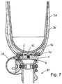
- FIG. 7 shows a section of a prosthesis system according to an embodiment of the present invention.
- a prosthesis shaft 36 in which a liner 38 is located, a prosthetic stump of the patient is used.
- the adapter element 1 With the channel 6 located therein.
- the adapter element 1 is arranged on the prosthesis shaft 36 via a fastening device 40.
- a through-bore 42 In the attachment device 40 is a through-bore 42, through which the channel 6 of the adapter element 1 is connected to an internal volume 44 which extends between the liner 38 and the prosthesis shaft 36.
- the first output 4 is connected to the through hole 42 of the fastening device 40, the pump housing 18 is arranged, as it is already in FIG. 2 is shown. In FIG. 7 downwards extends the prosthesis assembly 20, which will not be discussed further here.
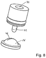
- FIG. 8 shows a schematic representation of a particular embodiment of a Domventils.
- the pin 22 is shown, in which the passage 34 is located.
- a flow through the membrane 26 is only possible in a direction from bottom to top.
- the longitudinal slot 46 opens in the membrane 26 and leaves the flowing medium air in the present case, happen.
- a flow through the membrane 26 in the reverse direction is not possible, since in this case the longitudinal slot 46 and thus the membrane 26 remain closed.
- valve 24 If the valve 24 is operated in this mode, there is a pressure difference such that before the valve 24, ie on the side of the pin 22, a significantly higher pressure prevails than behind the valve 24, since the valve 24 on this side with the interior 44 is connected, in which there is a negative pressure.
- the pin 22 in in FIG. 8 shown embodiment moves downward, it pierces the membrane 26 and penetrates through the longitudinal slot 46 a. As a result, the membrane 26 is opened so that air can also be passed through the passage 34 in a flow direction from top to bottom.
- FIG. 9 shows another embodiment of in FIG. 8 shown components.
- the membrane 26 again has a longitudinal slot 46.
- the pin 22, through which the passage 34 passes, however, does not penetrate the membrane 26, but is equipped with a pressure edge 48. Now, if the pin 22 moves toward the diaphragm 26, the pin 22 does not pierce the membrane 26, but exerts a pressure on the membrane 26 through the pressure edge 48, whereby also the longitudinal slot 46 is opened and the valve 24, the two Includes components that can be used in the form of a two-way valve.
- FIG. 10 are the in FIG. 9 shown components shown from a different angle.
- the advantage of this embodiment over the in FIG. 8 shown representation of a pin 22 is that the pin 22 in the Figures 9 and 10 shown embodiment, the longitudinal slot 46 of the membrane 26 does not have to pierce and therefore can not damage it when piercing and pulling out.
- FIG. 11 shows the situation in which the pin 22 according to the Figures 9 and 10 , abuts the diaphragm 26 of the valve 24.
- the longitudinal slot 46 opens and the valve 24 can be used as a two-way valve.
- FIG. 12 shows the schematic representation of a prosthetic system according to an embodiment of the present invention.
- the prosthesis assembly 20 extends.
- the adapter element 1 which is almost completely covered in the present embodiment by a connection plate 50 attached to it.
- the connecting plate 50 has latching or snap-action elements 52, by means of which the pump housing 18 can be connected to the connecting plate 50.
- different control element 50 are provided, through which the function of the pump can be influenced.
- connection plate 50 By providing the separate connection plate 50 with the detent or snap elements 52 located thereon, a particularly simple, yet safe and space-saving option is provided for securing the pump housing 18.
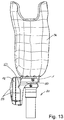
- FIG. 13 shows the prosthesis system FIG. 12 in a side view. Due to the special design of the connecting plate 50, it is possible to attach the pump housing 18 as space-saving and inconspicuous as possible, yet to ensure good accessibility by the wearer of the prosthesis system.
- FIG. 14 is the prosthesis system from the Figures 12 and 13 shown in which the pump housing 18 has been removed.
- the connecting plate 50 in the exemplary embodiment shown has three latching or snap elements 52, by means of which a secure and vibration-proof mounting of the pump housing 18 to the connecting plate 50 is ensured.
- the adapter element 1 also has a force application element 16, which, as already described, can be designed, for example, in the form of a magnet.
- the second output 14 of the adapter element 1 is shown, to which the pump, not shown, is connected.
- FIG. 15 shows the representation of the Figures 12 and 13 in a sectional view.
- the through hole 42 which is connected via the first output 4 to the channel 6 of the adapter element 1.
- the valve 24 is shown.
- the middle area of the FIG. 15 is in FIG. 16 shown enlarged.
- the valve 24 has the membrane 26, for example, via a longitudinal slot 46, as he, for example, in the FIGS. 8 and 9 is displayed. Through this longitudinal slot abuts in FIG. 16 the pin 22 with the passage 34 therein. As a result, the valve 24 in the in FIG. 16 operated situation shown in the form of a two-way valve, so that by the pump, which is pump housing 18, the inner volume 44, which extends between the prosthesis shaft 36 and the in FIG. 16 Not shown liner 38 is located, can be evacuated.
- FIG. 17 shows the adapter element 1 with the channel 6, the first output 4 and in the second output 14, in which the valve 24 is located with the diaphragm 26 which is pierced by the pin 22 of the pump.
- a sealing element 82 is arranged, which allows an airtight connection to the fastening device 40 of a prosthesis shaft, not shown. In this is the through hole 42.
- the in FIG. 17 shown adapter element 1 also has a third output 56, in which a closing element 58 is located. This has a one-way valve 60, which allows air to escape only in the FIG. 17 illustrated embodiment allowed to the right.
- the terminating element 58 is in FIG. 18 shown in more detail.
- valve diaphragm 62 which allows air passage in the illustration shown from left to right, but prevented from right to left.
- the valve membrane 62 is located between a valve holder 64 and a valve housing 66.
- a sealing ring 68 In the valve housing 66 is a sealing ring 68, which prevents air between the wall of the third output 56 and the valve housing 66 passes.
- a protective cap 70 is shown, which protects the valve from contamination.
- an outlet bore 72 through which Gas that has passed through the valve, the termination member 58 may leave the cap 70 over.
- FIG. 19 shows a schematic sectional view through a section of a prosthetic system. It can be seen the adapter element, which has the first channel 6, which has the third output 56 in the illustrated embodiment. However, this is not the final element 58, as it is in FIG. 18 is shown, but a hose connection 74, on which a hose 76 is arranged. This is connected to the through hole 42 in the prosthesis shaft 36. By an arranged pump 78, which is connected to the second output 14, so air is pumped out through the hose connection 74 and the tube 76 from the prosthesis shaft 36. The first outlet 4 of the channel 6 is closed by a closure element 80.
- the embodiment shown is of interest in the case when the fastening device 40 of the prosthesis shaft 36 has no through hole on the side facing the first outlet 4.
- FIG. 20 shows an enlarged section FIG. 19 .
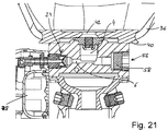
- FIG. 21 shows the same section, but now the fastening device 40 of the prosthesis shaft 36 on the first output 4 side facing the through hole 42 and is connected via the sealing element 82 with the adapter element 1.
- the pump 78 thus pumps out through the valve 24 air out of the channel 6, which enters through the first output 4 and the through hole 42 from the inner region of the prosthesis shaft 36 into the channel 6.
- the third output 56 is closed in the embodiment shown with the closing element 58.
- the closure element 58 shown here only forms a closure, so that air can neither penetrate through the third outlet 56 into the channel 6 nor escape from it. In this way, the same function is achieved as in the in FIG. 15 shown embodiment, in which the adapter element 1 and the at least one channel 6 only has a first output 4 and a second output 14.
- FIG. 22 shows again a corresponding section, in which the adapter element 1 is connected to the fastening device 40 of the prosthesis shaft 36 via the sealing element 82.
- the through hole 42 is again in the fastening device 40 and thus at the first output 4 of the channel 6 facing side.
- the pump 78 pumps so as in the in FIG. 21 illustrated embodiment, air from the interior of the prosthesis stem 21 out.
- the third output 56 is now the final element 58, which is already in FIG. 18 is shown. Air from the channel 6 can thus leave the channel 6 through the terminating element 58 and the third output 56. This is particularly advantageous if, for example, gas accumulates in the prosthesis socket 36 of the prosthesis system due to a small leakage.
- this gas By a walking movement of the patient, this gas is pressed through the through hole 42 in the channel 6. If the pump 78 is not in operation, the gas can not leave the channel through the second outlet 14. Instead, it is possible to remove the gas from the channel 6 and thus maintain the vacuum desired within the prosthesis socket to hold the prosthesis to the patient's amputation stump without having to turn on the pump 78. This can save energy, reduce noise and also increase the life of the pump.
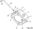
- FIG. 23 shows the adapter element 1 according to another embodiment of the present invention. It has four holes 8 as well as connecting means 12, which in the in FIG. 23 shown embodiment in the form of hook-shaped projections which extend over almost the entire side length of the adapter element 1 is formed are. On a side surface of the second output 14 can be seen.
- a plug element 84 is shown, which has at its two ends via a respective socket wrench 86.
- the plug-in element 84 can be inserted into an insertion hole 88 provided for this purpose in the adapter element 1.
- FIG. 23 there is another insertion hole 88 which is arranged so that the two insertion holes 88 on the adapter element 1 and on the pump housing 18 are aligned.
- the plug element 84 is inserted into the insertion holes 88 and thus ensures a locking and fastening of the two components together.
- FIG. 23 is on the adapter element 1 also a ball pin hole 90 to recognize, in which a FIG. 23 not shown ball pin is guided spring loaded. If the plug-in element 84 is inserted into the insertion bore 88, there is a displacement of the ball stud against the spring loading it, so that here a further attachment and reinforcement of the connection is achieved.
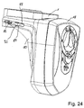
- FIG. 24 shows the adapter element 1, which with the pump housing 18 on the already in FIG. 13 illustrated connecting plate 50 is connected.
- the protruding portion of the plug-in element 84 is arranged in a clip element 92 and secured against slipping out of the insertion holes 88.
- At the end of the plug-in element of the socket key 86 is shown.
- FIG. 25 shows the adapter element 1 and a part of the pump housing 18 in a sectional view. It can be seen laterally on the adapter element 1, the connecting means 12 which have a hook-shaped cross-section and were inserted into a correspondingly shaped groove on the pump housing 18. The section of the sectional view of FIG. 25 passes exactly through the insertion hole 88, in the FIG. 25 the plug element 84 is shown. The protruding end is again arranged in the clip element 92 and secured against slipping out.
- a ball pin 94 is now shown, which by a spring, not shown in FIG. 25 down spring loaded.
- a spring not shown in FIG. 25 down spring loaded.
Landscapes
- Health & Medical Sciences (AREA)
- Cardiology (AREA)
- Oral & Maxillofacial Surgery (AREA)
- Transplantation (AREA)
- Engineering & Computer Science (AREA)
- Biomedical Technology (AREA)
- Heart & Thoracic Surgery (AREA)
- Vascular Medicine (AREA)
- Life Sciences & Earth Sciences (AREA)
- Animal Behavior & Ethology (AREA)
- General Health & Medical Sciences (AREA)
- Public Health (AREA)
- Veterinary Medicine (AREA)
- Prostheses (AREA)
Claims (12)
- Agencement pour relier une pompe à un perçage traversant (42) ménagé dans une tige de prothèse (36), dans lequel le système inclut au moins un canal, avec
une première sortie (4) à relier au perçage traversant (42) ménagé dans la tige de prothèse (36), et
une seconde sortie (14) susceptible d'être reliée à la pompe,
et au moins une valve (24)
dans lequel la valve (24) est susceptible d'être amenée dans un premier mode et dans un second mode, de sorte que, dans le premier mode, la valve (24) est une valve à une voie, qui permet uniquement un écoulement depuis la première sortie (4) vers la seconde sortie (14),
caractérisé en ce que, dans le second mode, la valve est une valve à deux voies, de sorte que de l'air peut s'écouler à travers le canal dans les deux directions, et de sorte que la valve est traversée à chaque fois par l'écoulement. - Agencement selon la revendication 1,
caractérisé en ce que la valve (24) inclut une membrane (26) et est susceptible d'être amenée du premier mode au second mode du fait que la membrane (26) est soit traversée par un élément de perçage (22), soit ouverte par une pression appliquée sur la membrane (26). - Système selon l'une des revendications précédentes,
caractérisé en ce que ledit au moins un canal (6) comporte une troisième sortie (56) à relier au perçage traversant (42) ménagé dans la tige de prothèse (36) et un élément de terminaison (58), lequel peut être relié à la troisième sortie (56) et, dans une situation reliée, empêche un écoulement entrant via la troisième sortie (56) vers ledit au moins un canal (6). - Agencement selon la revendication 3,
caractérisé en ce que l'élément de terminaison (58) comprend une valve à une voie (60) qui, dans la situation reliée de l'élément de terminaison (58) avec la troisième sortie (56), autorise uniquement un écoulement sortant via la troisième sortie (56) hors dudit au moins un canal (6). - Système avec un agencement selon l'une des revendications précédentes et une pompe avec un boîtier de pompe (18), dans lequel des organes de liaison (12) qui se correspondent mutuellement sont réalisés sur le boîtier de pompe (18) et sur l'agencement, organes au moyen desquels l'agencement est susceptible d'être relié au boîtier de pompe (18).
- Système selon la revendication 5,
caractérisé en ce que les organes de liaison (12) sont réalisés sous la forme d'au moins une gorge (10) et d'une languette (28) correspondant à la gorge (10). - Système selon la revendication 5,
caractérisé en ce que les organes de liaison (12) incluent une plaque de liaison (50) prévue sur l'agencement. - Système selon la revendication 5, 6 ou 7,
caractérisé en ce qu'une broche (22) dépassant vers l'extérieur est agencée sur le boîtier de pompe (18), laquelle est réalisée de telle façon qu'elle perce la membrane (26), ou bien que la membrane (26) est ouverte par la pression appliquée sur la membrane (26), quand le boîtier de pompe (18) est relié à l'agencement. - Système selon l'une des revendications 5 à 8,
caractérisé en ce qu'un élément d'application de force (16) respectif est agencé sur le boîtier de pompe (18) et sur l'agencement, éléments qui provoquent conjointement une force quand le boîtier de pompe (18) est relié à l'agencement, ladite force étant opposée à un détachement du boîtier de pompe (18) depuis l'agencement. - Système selon la revendication 9,
caractérisé en ce qu'un perçage d'introduction (88) respectif est ménagé sur le boîtier de pompe (18) et sur l'agencement, perçages qui sont alignés l'un avec l'autre dans la situation reliée, de sorte qu'un élément d'enfichage (84) est susceptible d'être passé à travers le perçage d'introduction (88). - Système de prothèse comprenant une tige de prothèse, un agencement selon l'une des revendications 1 à 4, et une superstructure de prothèse (20).
- Système de prothèse comprenant une tige de prothèse, un système selon l'une des revendications 5 à 10, et une superstructure de prothèse (20).
Applications Claiming Priority (3)
| Application Number | Priority Date | Filing Date | Title |
|---|---|---|---|
| DE201110119593 DE102011119593B4 (de) | 2011-11-29 | 2011-11-29 | Adapter und Prothesensystem |
| DE201210011681 DE102012011681B4 (de) | 2012-06-14 | 2012-06-14 | Adapter und Prothesensystem |
| PCT/EP2012/004931 WO2013079202A1 (fr) | 2011-11-29 | 2012-11-29 | Dispositif et système de prothèse |
Publications (2)
| Publication Number | Publication Date |
|---|---|
| EP2785287A1 EP2785287A1 (fr) | 2014-10-08 |
| EP2785287B1 true EP2785287B1 (fr) | 2016-05-25 |
Family
ID=47297097
Family Applications (1)
| Application Number | Title | Priority Date | Filing Date |
|---|---|---|---|
| EP12797712.2A Active EP2785287B1 (fr) | 2011-11-29 | 2012-11-29 | Dispositif et système de prothèse |
Country Status (3)
| Country | Link |
|---|---|
| US (1) | US9615945B2 (fr) |
| EP (1) | EP2785287B1 (fr) |
| WO (1) | WO2013079202A1 (fr) |
Families Citing this family (1)
| Publication number | Priority date | Publication date | Assignee | Title |
|---|---|---|---|---|
| US10842653B2 (en) | 2007-09-19 | 2020-11-24 | Ability Dynamics, Llc | Vacuum system for a prosthetic foot |
Family Cites Families (25)
| Publication number | Priority date | Publication date | Assignee | Title |
|---|---|---|---|---|
| DE746781C (de) * | 1942-01-29 | 1944-08-23 | Heinrich Brandenbergs | Selbsttaetiges Be- und Entlueftungsventil fuer kuenstliche Glieder |
| US3901272A (en) * | 1974-01-04 | 1975-08-26 | Ford Motor Co | Unidirectional flow control valve |
| US4143853A (en) * | 1977-07-14 | 1979-03-13 | Metatech Corporation | Valve for use with a catheter or the like |
| US4341239A (en) * | 1980-07-14 | 1982-07-27 | Vernay Laboratories, Inc. | Combination check-overpressure relief valve |
| SE445968B (sv) * | 1982-09-10 | 1986-08-04 | Kjell Goran Engstrom | Ventil for sugprotes |
| US5249598A (en) * | 1992-08-03 | 1993-10-05 | Vernay Laboratories, Inc. | Bi-directional vent and overpressure relief valve |
| US5702489A (en) | 1995-08-18 | 1997-12-30 | Materials Engineering And Development, Inc. | Valve assembly for a prosthetic limb |
| US6063125A (en) * | 1997-02-14 | 2000-05-16 | Ohio Willow Wood Company | Suspension/alignment for prosthetic limbs |
| US6926742B2 (en) | 1999-06-03 | 2005-08-09 | Otto Bock Healthcare Lp | Plate/socket attachment for artificial limb vacuum pump |
| AU736326B3 (en) * | 2001-02-23 | 2001-07-26 | Occupational & Medical Innovations Ltd | A needle free access valve |
| US7025744B2 (en) * | 2002-10-04 | 2006-04-11 | Dsu Medical Corporation | Injection site for male luer or other tubular connector |
| US7351367B2 (en) * | 2003-04-11 | 2008-04-01 | Bionix Prosthetic Solutions, Inc. | Adapter bracket for prostheses, method and apparatus for forming prosthetic device with transfer of proper alignment |
| EP1653893A4 (fr) | 2003-06-20 | 2009-11-11 | Ossur Hf | Emboiture prothetique a reservoir sous vide autonome |
| WO2005039444A2 (fr) * | 2003-10-24 | 2005-05-06 | Collier Milo S | Dispositif prothetique a depression |
| AU2005237488B2 (en) * | 2004-04-22 | 2010-02-25 | Otto Bock Healthcare Lp | Vacuum pump with shock absorption and controlled rotation for prosthetic devices |
| US7427298B1 (en) * | 2005-02-02 | 2008-09-23 | Bionix Prosthetic Solutions, Llc | Prosthetic socket lock valve |
| US20070213839A1 (en) * | 2005-03-16 | 2007-09-13 | Thure Nachbar | Artificial limb assembly having microprocessor-controlled vacuum pump |
| WO2006135851A2 (fr) | 2005-06-10 | 2006-12-21 | The Ohio Willow Wood Company | Dispositif prothetique dans lequel est utilisee une pompe a vide electrique |
| US8182547B2 (en) | 2005-09-08 | 2012-05-22 | Charles King | Negative gauge pressure moisture management and secure adherence artificial limb system and associated methods |
| FR2903294B1 (fr) * | 2006-07-06 | 2009-02-13 | Pierre Chabloz | Dispositif de jonction par emboitement etanche entre une prothese et un manchon installe sur le moignon d'un membre ampute, et prothese equipee d'un tel dispositif de jonction |
| WO2008033337A2 (fr) | 2006-09-12 | 2008-03-20 | James Jay Martin | Système d'attache sous vide |
| WO2009149412A1 (fr) | 2008-06-06 | 2009-12-10 | Hanger Orthopedic Group, Inc. | Dispositif prothétique et système de raccordement employant du vide |
| US7927377B2 (en) | 2008-06-09 | 2011-04-19 | Prosthetic Design, Inc. | Elevated vacuum locking system |
| WO2010036370A1 (fr) | 2008-09-26 | 2010-04-01 | Craig Mackenzie | Système de plaque de montage, plaque de réservoir sous vide et système de pompe électronique pour douille prothétique |
| US8113235B2 (en) * | 2008-10-03 | 2012-02-14 | David Robert Bogue | Apparatus and methods for facilitating prosthesis donning, doffing, retention, and fit |
-
2012
- 2012-11-29 EP EP12797712.2A patent/EP2785287B1/fr active Active
- 2012-11-29 US US14/360,914 patent/US9615945B2/en active Active
- 2012-11-29 WO PCT/EP2012/004931 patent/WO2013079202A1/fr not_active Ceased
Also Published As
| Publication number | Publication date |
|---|---|
| EP2785287A1 (fr) | 2014-10-08 |
| US20140296998A1 (en) | 2014-10-02 |
| US9615945B2 (en) | 2017-04-11 |
| WO2013079202A1 (fr) | 2013-06-06 |
Similar Documents
| Publication | Publication Date | Title |
|---|---|---|
| DE102014001937B3 (de) | Atemschutzmaske | |
| DE102006034161B4 (de) | Ventile mit Zugangsöffnung, die keine Nadel benötigt | |
| EP1441675A2 (fr) | Emboiture de prothese pourvue d'un joint a son extremite distale | |
| DE102012005093A1 (de) | Membranventil | |
| WO2018178221A1 (fr) | Dispositif d'aspiration | |
| WO2015067332A1 (fr) | Douche nasale avec valve pouvant être actionnée par l'air respiratoire | |
| CH701721B1 (de) | Tragbarer Zeitmesser mit Entgasungsventil. | |
| DE10320143A1 (de) | Vernebleranschlussvorrichtung für Beatmungsgeräte oder dergleichen | |
| DE102017104155B4 (de) | Einwegventil-Baugruppe | |
| DE202004009831U1 (de) | Rückschlagventil | |
| EP2913082B1 (fr) | Masque respiratoire protecteur | |
| EP2805748B1 (fr) | Masque respiratoire doté d'une soupape de respiration de secours | |
| DE8804229U1 (de) | Steuerbares Rückschlagventil | |
| DE102012011681B4 (de) | Adapter und Prothesensystem | |
| DE102011119593B4 (de) | Adapter und Prothesensystem | |
| EP1678434A1 (fr) | Soupape, notamment soupape de securite a gaz | |
| EP3933236B1 (fr) | Soupape de commande pneumatique, agencement de soupape et système respiratoire | |
| EP2785287A1 (fr) | Dispositif et système de prothèse | |
| DE10153796A1 (de) | Prothesenschaft mit Dichtung am distalen Ende | |
| DE3545393A1 (de) | Vorrichtung aus funktionellen verbindungsgliedern fuer einen pneumatikzylinder zur kombinierten montage, um mindestens zwei funktionen zu gewaehrleisten | |
| DE69728321T2 (de) | Fernbedienungsgehäuse mit einem mittels Drucktaste betätigten Modul | |
| EP2198684B1 (fr) | Boîtier de soupape de commande et support de buses pour dispositif de pulvérisation pour la technique agricole | |
| EP1978262A1 (fr) | Dispositif d'entraînement | |
| DE102006044722B4 (de) | Zwei-Wege-Ventil | |
| EP2787133A1 (fr) | Dispositifs sanitaires |
Legal Events
| Date | Code | Title | Description |
|---|---|---|---|
| PUAI | Public reference made under article 153(3) epc to a published international application that has entered the european phase |
Free format text: ORIGINAL CODE: 0009012 |
|
| 17P | Request for examination filed |
Effective date: 20140627 |
|
| AK | Designated contracting states |
Kind code of ref document: A1 Designated state(s): AL AT BE BG CH CY CZ DE DK EE ES FI FR GB GR HR HU IE IS IT LI LT LU LV MC MK MT NL NO PL PT RO RS SE SI SK SM TR |
|
| RIN1 | Information on inventor provided before grant (corrected) |
Inventor name: SCHOENEMEIER, MARK Inventor name: MOSLER, LUEDER Inventor name: HILLMANN, MARTIN Inventor name: MUELLER, ANDRE |
|
| DAX | Request for extension of the european patent (deleted) | ||
| 17Q | First examination report despatched |
Effective date: 20150624 |
|
| GRAP | Despatch of communication of intention to grant a patent |
Free format text: ORIGINAL CODE: EPIDOSNIGR1 |
|
| INTG | Intention to grant announced |
Effective date: 20160129 |
|
| GRAS | Grant fee paid |
Free format text: ORIGINAL CODE: EPIDOSNIGR3 |
|
| GRAA | (expected) grant |
Free format text: ORIGINAL CODE: 0009210 |
|
| AK | Designated contracting states |
Kind code of ref document: B1 Designated state(s): AL AT BE BG CH CY CZ DE DK EE ES FI FR GB GR HR HU IE IS IT LI LT LU LV MC MK MT NL NO PL PT RO RS SE SI SK SM TR |
|
| REG | Reference to a national code |
Ref country code: GB Ref legal event code: FG4D Free format text: NOT ENGLISH |
|
| REG | Reference to a national code |
Ref country code: CH Ref legal event code: EP |
|
| REG | Reference to a national code |
Ref country code: IE Ref legal event code: FG4D Free format text: LANGUAGE OF EP DOCUMENT: GERMAN Ref country code: AT Ref legal event code: REF Ref document number: 801612 Country of ref document: AT Kind code of ref document: T Effective date: 20160615 |
|
| REG | Reference to a national code |
Ref country code: DE Ref legal event code: R096 Ref document number: 502012007270 Country of ref document: DE |
|
| REG | Reference to a national code |
Ref country code: LT Ref legal event code: MG4D |
|
| REG | Reference to a national code |
Ref country code: NL Ref legal event code: MP Effective date: 20160525 |
|
| PG25 | Lapsed in a contracting state [announced via postgrant information from national office to epo] |
Ref country code: LT Free format text: LAPSE BECAUSE OF FAILURE TO SUBMIT A TRANSLATION OF THE DESCRIPTION OR TO PAY THE FEE WITHIN THE PRESCRIBED TIME-LIMIT Effective date: 20160525 Ref country code: FI Free format text: LAPSE BECAUSE OF FAILURE TO SUBMIT A TRANSLATION OF THE DESCRIPTION OR TO PAY THE FEE WITHIN THE PRESCRIBED TIME-LIMIT Effective date: 20160525 Ref country code: NO Free format text: LAPSE BECAUSE OF FAILURE TO SUBMIT A TRANSLATION OF THE DESCRIPTION OR TO PAY THE FEE WITHIN THE PRESCRIBED TIME-LIMIT Effective date: 20160825 Ref country code: NL Free format text: LAPSE BECAUSE OF FAILURE TO SUBMIT A TRANSLATION OF THE DESCRIPTION OR TO PAY THE FEE WITHIN THE PRESCRIBED TIME-LIMIT Effective date: 20160525 |
|
| REG | Reference to a national code |
Ref country code: FR Ref legal event code: PLFP Year of fee payment: 5 |
|
| PG25 | Lapsed in a contracting state [announced via postgrant information from national office to epo] |
Ref country code: GR Free format text: LAPSE BECAUSE OF FAILURE TO SUBMIT A TRANSLATION OF THE DESCRIPTION OR TO PAY THE FEE WITHIN THE PRESCRIBED TIME-LIMIT Effective date: 20160826 Ref country code: SE Free format text: LAPSE BECAUSE OF FAILURE TO SUBMIT A TRANSLATION OF THE DESCRIPTION OR TO PAY THE FEE WITHIN THE PRESCRIBED TIME-LIMIT Effective date: 20160525 Ref country code: PT Free format text: LAPSE BECAUSE OF FAILURE TO SUBMIT A TRANSLATION OF THE DESCRIPTION OR TO PAY THE FEE WITHIN THE PRESCRIBED TIME-LIMIT Effective date: 20160926 Ref country code: ES Free format text: LAPSE BECAUSE OF FAILURE TO SUBMIT A TRANSLATION OF THE DESCRIPTION OR TO PAY THE FEE WITHIN THE PRESCRIBED TIME-LIMIT Effective date: 20160525 Ref country code: LV Free format text: LAPSE BECAUSE OF FAILURE TO SUBMIT A TRANSLATION OF THE DESCRIPTION OR TO PAY THE FEE WITHIN THE PRESCRIBED TIME-LIMIT Effective date: 20160525 Ref country code: RS Free format text: LAPSE BECAUSE OF FAILURE TO SUBMIT A TRANSLATION OF THE DESCRIPTION OR TO PAY THE FEE WITHIN THE PRESCRIBED TIME-LIMIT Effective date: 20160525 |
|
| PG25 | Lapsed in a contracting state [announced via postgrant information from national office to epo] |
Ref country code: IT Free format text: LAPSE BECAUSE OF FAILURE TO SUBMIT A TRANSLATION OF THE DESCRIPTION OR TO PAY THE FEE WITHIN THE PRESCRIBED TIME-LIMIT Effective date: 20160525 |
|
| PG25 | Lapsed in a contracting state [announced via postgrant information from national office to epo] |
Ref country code: RO Free format text: LAPSE BECAUSE OF FAILURE TO SUBMIT A TRANSLATION OF THE DESCRIPTION OR TO PAY THE FEE WITHIN THE PRESCRIBED TIME-LIMIT Effective date: 20160525 Ref country code: EE Free format text: LAPSE BECAUSE OF FAILURE TO SUBMIT A TRANSLATION OF THE DESCRIPTION OR TO PAY THE FEE WITHIN THE PRESCRIBED TIME-LIMIT Effective date: 20160525 Ref country code: CZ Free format text: LAPSE BECAUSE OF FAILURE TO SUBMIT A TRANSLATION OF THE DESCRIPTION OR TO PAY THE FEE WITHIN THE PRESCRIBED TIME-LIMIT Effective date: 20160525 Ref country code: SK Free format text: LAPSE BECAUSE OF FAILURE TO SUBMIT A TRANSLATION OF THE DESCRIPTION OR TO PAY THE FEE WITHIN THE PRESCRIBED TIME-LIMIT Effective date: 20160525 Ref country code: DK Free format text: LAPSE BECAUSE OF FAILURE TO SUBMIT A TRANSLATION OF THE DESCRIPTION OR TO PAY THE FEE WITHIN THE PRESCRIBED TIME-LIMIT Effective date: 20160525 |
|
| PG25 | Lapsed in a contracting state [announced via postgrant information from national office to epo] |
Ref country code: PL Free format text: LAPSE BECAUSE OF FAILURE TO SUBMIT A TRANSLATION OF THE DESCRIPTION OR TO PAY THE FEE WITHIN THE PRESCRIBED TIME-LIMIT Effective date: 20160525 Ref country code: SM Free format text: LAPSE BECAUSE OF FAILURE TO SUBMIT A TRANSLATION OF THE DESCRIPTION OR TO PAY THE FEE WITHIN THE PRESCRIBED TIME-LIMIT Effective date: 20160525 Ref country code: BE Free format text: LAPSE BECAUSE OF NON-PAYMENT OF DUE FEES Effective date: 20161130 |
|
| REG | Reference to a national code |
Ref country code: DE Ref legal event code: R097 Ref document number: 502012007270 Country of ref document: DE |
|
| PLBE | No opposition filed within time limit |
Free format text: ORIGINAL CODE: 0009261 |
|
| STAA | Information on the status of an ep patent application or granted ep patent |
Free format text: STATUS: NO OPPOSITION FILED WITHIN TIME LIMIT |
|
| 26N | No opposition filed |
Effective date: 20170228 |
|
| PG25 | Lapsed in a contracting state [announced via postgrant information from national office to epo] |
Ref country code: SI Free format text: LAPSE BECAUSE OF FAILURE TO SUBMIT A TRANSLATION OF THE DESCRIPTION OR TO PAY THE FEE WITHIN THE PRESCRIBED TIME-LIMIT Effective date: 20160525 |
|
| REG | Reference to a national code |
Ref country code: CH Ref legal event code: PL |
|
| GBPC | Gb: european patent ceased through non-payment of renewal fee |
Effective date: 20161129 |
|
| PG25 | Lapsed in a contracting state [announced via postgrant information from national office to epo] |
Ref country code: CH Free format text: LAPSE BECAUSE OF NON-PAYMENT OF DUE FEES Effective date: 20161130 Ref country code: LI Free format text: LAPSE BECAUSE OF NON-PAYMENT OF DUE FEES Effective date: 20161130 |
|
| REG | Reference to a national code |
Ref country code: IE Ref legal event code: MM4A |
|
| PG25 | Lapsed in a contracting state [announced via postgrant information from national office to epo] |
Ref country code: LU Free format text: LAPSE BECAUSE OF NON-PAYMENT OF DUE FEES Effective date: 20161130 |
|
| REG | Reference to a national code |
Ref country code: FR Ref legal event code: PLFP Year of fee payment: 6 |
|
| PG25 | Lapsed in a contracting state [announced via postgrant information from national office to epo] |
Ref country code: GB Free format text: LAPSE BECAUSE OF NON-PAYMENT OF DUE FEES Effective date: 20161129 Ref country code: IE Free format text: LAPSE BECAUSE OF NON-PAYMENT OF DUE FEES Effective date: 20161129 |
|
| REG | Reference to a national code |
Ref country code: BE Ref legal event code: MM Effective date: 20161130 |
|
| PG25 | Lapsed in a contracting state [announced via postgrant information from national office to epo] |
Ref country code: HU Free format text: LAPSE BECAUSE OF FAILURE TO SUBMIT A TRANSLATION OF THE DESCRIPTION OR TO PAY THE FEE WITHIN THE PRESCRIBED TIME-LIMIT; INVALID AB INITIO Effective date: 20121129 |
|
| PG25 | Lapsed in a contracting state [announced via postgrant information from national office to epo] |
Ref country code: HR Free format text: LAPSE BECAUSE OF FAILURE TO SUBMIT A TRANSLATION OF THE DESCRIPTION OR TO PAY THE FEE WITHIN THE PRESCRIBED TIME-LIMIT Effective date: 20160525 Ref country code: MC Free format text: LAPSE BECAUSE OF FAILURE TO SUBMIT A TRANSLATION OF THE DESCRIPTION OR TO PAY THE FEE WITHIN THE PRESCRIBED TIME-LIMIT Effective date: 20160525 Ref country code: MK Free format text: LAPSE BECAUSE OF FAILURE TO SUBMIT A TRANSLATION OF THE DESCRIPTION OR TO PAY THE FEE WITHIN THE PRESCRIBED TIME-LIMIT Effective date: 20160525 Ref country code: IS Free format text: LAPSE BECAUSE OF FAILURE TO SUBMIT A TRANSLATION OF THE DESCRIPTION OR TO PAY THE FEE WITHIN THE PRESCRIBED TIME-LIMIT Effective date: 20160525 Ref country code: CY Free format text: LAPSE BECAUSE OF FAILURE TO SUBMIT A TRANSLATION OF THE DESCRIPTION OR TO PAY THE FEE WITHIN THE PRESCRIBED TIME-LIMIT Effective date: 20160525 |
|
| PG25 | Lapsed in a contracting state [announced via postgrant information from national office to epo] |
Ref country code: BG Free format text: LAPSE BECAUSE OF FAILURE TO SUBMIT A TRANSLATION OF THE DESCRIPTION OR TO PAY THE FEE WITHIN THE PRESCRIBED TIME-LIMIT Effective date: 20160525 |
|
| REG | Reference to a national code |
Ref country code: DE Ref legal event code: R082 Ref document number: 502012007270 Country of ref document: DE Representative=s name: GRAMM, LINS & PARTNER PATENT- UND RECHTSANWAEL, DE Ref country code: DE Ref legal event code: R081 Ref document number: 502012007270 Country of ref document: DE Owner name: OTTOBOCK SE & CO. KGAA, DE Free format text: FORMER OWNER: OTTO BOCK HEALTHCARE GMBH, 37115 DUDERSTADT, DE |
|
| PG25 | Lapsed in a contracting state [announced via postgrant information from national office to epo] |
Ref country code: MT Free format text: LAPSE BECAUSE OF FAILURE TO SUBMIT A TRANSLATION OF THE DESCRIPTION OR TO PAY THE FEE WITHIN THE PRESCRIBED TIME-LIMIT Effective date: 20160525 |
|
| PG25 | Lapsed in a contracting state [announced via postgrant information from national office to epo] |
Ref country code: AL Free format text: LAPSE BECAUSE OF FAILURE TO SUBMIT A TRANSLATION OF THE DESCRIPTION OR TO PAY THE FEE WITHIN THE PRESCRIBED TIME-LIMIT Effective date: 20160525 |
|
| REG | Reference to a national code |
Ref country code: AT Ref legal event code: MM01 Ref document number: 801612 Country of ref document: AT Kind code of ref document: T Effective date: 20171129 |
|
| PG25 | Lapsed in a contracting state [announced via postgrant information from national office to epo] |
Ref country code: AT Free format text: LAPSE BECAUSE OF NON-PAYMENT OF DUE FEES Effective date: 20171129 |
|
| PGFP | Annual fee paid to national office [announced via postgrant information from national office to epo] |
Ref country code: FR Payment date: 20191121 Year of fee payment: 8 |
|
| PGFP | Annual fee paid to national office [announced via postgrant information from national office to epo] |
Ref country code: TR Payment date: 20191126 Year of fee payment: 8 |
|
| PG25 | Lapsed in a contracting state [announced via postgrant information from national office to epo] |
Ref country code: FR Free format text: LAPSE BECAUSE OF NON-PAYMENT OF DUE FEES Effective date: 20201130 |
|
| PG25 | Lapsed in a contracting state [announced via postgrant information from national office to epo] |
Ref country code: TR Free format text: LAPSE BECAUSE OF NON-PAYMENT OF DUE FEES Effective date: 20201129 |
|
| PGFP | Annual fee paid to national office [announced via postgrant information from national office to epo] |
Ref country code: DE Payment date: 20251118 Year of fee payment: 14 |