EP2785491B1 - Procédé pour réparer une aube directrice variable - Google Patents
Procédé pour réparer une aube directrice variable Download PDFInfo
- Publication number
- EP2785491B1 EP2785491B1 EP12797709.8A EP12797709A EP2785491B1 EP 2785491 B1 EP2785491 B1 EP 2785491B1 EP 12797709 A EP12797709 A EP 12797709A EP 2785491 B1 EP2785491 B1 EP 2785491B1
- Authority
- EP
- European Patent Office
- Prior art keywords
- variable guide
- guide vane
- variable
- vane
- vanes
- Prior art date
- Legal status (The legal status is an assumption and is not a legal conclusion. Google has not performed a legal analysis and makes no representation as to the accuracy of the status listed.)
- Active
Links
Images

Classifications
-
- B—PERFORMING OPERATIONS; TRANSPORTING
- B23—MACHINE TOOLS; METAL-WORKING NOT OTHERWISE PROVIDED FOR
- B23P—METAL-WORKING NOT OTHERWISE PROVIDED FOR; COMBINED OPERATIONS; UNIVERSAL MACHINE TOOLS
- B23P6/00—Restoring or reconditioning objects
- B23P6/002—Repairing turbine components, e.g. moving or stationary blades, rotors
- B23P6/007—Repairing turbine components, e.g. moving or stationary blades, rotors using only additive methods, e.g. build-up welding
-
- B—PERFORMING OPERATIONS; TRANSPORTING
- B23—MACHINE TOOLS; METAL-WORKING NOT OTHERWISE PROVIDED FOR
- B23K—SOLDERING OR UNSOLDERING; WELDING; CLADDING OR PLATING BY SOLDERING OR WELDING; CUTTING BY APPLYING HEAT LOCALLY, e.g. FLAME CUTTING; WORKING BY LASER BEAM
- B23K26/00—Working by laser beam, e.g. welding, cutting or boring
- B23K26/20—Bonding
- B23K26/32—Bonding taking account of the properties of the material involved
-
- B—PERFORMING OPERATIONS; TRANSPORTING
- B23—MACHINE TOOLS; METAL-WORKING NOT OTHERWISE PROVIDED FOR
- B23K—SOLDERING OR UNSOLDERING; WELDING; CLADDING OR PLATING BY SOLDERING OR WELDING; CUTTING BY APPLYING HEAT LOCALLY, e.g. FLAME CUTTING; WORKING BY LASER BEAM
- B23K26/00—Working by laser beam, e.g. welding, cutting or boring
- B23K26/34—Laser welding for purposes other than joining
- B23K26/342—Build-up welding
-
- B—PERFORMING OPERATIONS; TRANSPORTING
- B23—MACHINE TOOLS; METAL-WORKING NOT OTHERWISE PROVIDED FOR
- B23K—SOLDERING OR UNSOLDERING; WELDING; CLADDING OR PLATING BY SOLDERING OR WELDING; CUTTING BY APPLYING HEAT LOCALLY, e.g. FLAME CUTTING; WORKING BY LASER BEAM
- B23K35/00—Rods, electrodes, materials, or media, for use in soldering, welding, or cutting
- B23K35/02—Rods, electrodes, materials, or media, for use in soldering, welding, or cutting characterised by mechanical features, e.g. shape
- B23K35/0222—Rods, electrodes, materials, or media, for use in soldering, welding, or cutting characterised by mechanical features, e.g. shape for use in soldering or brazing
- B23K35/0244—Powders, particles or spheres; Preforms made therefrom
-
- B—PERFORMING OPERATIONS; TRANSPORTING
- B23—MACHINE TOOLS; METAL-WORKING NOT OTHERWISE PROVIDED FOR
- B23K—SOLDERING OR UNSOLDERING; WELDING; CLADDING OR PLATING BY SOLDERING OR WELDING; CUTTING BY APPLYING HEAT LOCALLY, e.g. FLAME CUTTING; WORKING BY LASER BEAM
- B23K35/00—Rods, electrodes, materials, or media, for use in soldering, welding, or cutting
- B23K35/22—Rods, electrodes, materials, or media, for use in soldering, welding, or cutting characterised by the composition or nature of the material
- B23K35/24—Selection of soldering or welding materials proper
- B23K35/30—Selection of soldering or welding materials proper with the principal constituent melting at less than 1550°C
- B23K35/3033—Ni as the principal constituent
-
- F—MECHANICAL ENGINEERING; LIGHTING; HEATING; WEAPONS; BLASTING
- F01—MACHINES OR ENGINES IN GENERAL; ENGINE PLANTS IN GENERAL; STEAM ENGINES
- F01D—NON-POSITIVE DISPLACEMENT MACHINES OR ENGINES, e.g. STEAM TURBINES
- F01D17/00—Regulating or controlling by varying flow
- F01D17/10—Final actuators
- F01D17/12—Final actuators arranged in stator parts
- F01D17/14—Final actuators arranged in stator parts varying effective cross-sectional area of nozzles or guide conduits
- F01D17/16—Final actuators arranged in stator parts varying effective cross-sectional area of nozzles or guide conduits by means of nozzle vanes
- F01D17/162—Final actuators arranged in stator parts varying effective cross-sectional area of nozzles or guide conduits by means of nozzle vanes for axial flow, i.e. the vanes turning around axes which are essentially perpendicular to the rotor centre line
-
- F—MECHANICAL ENGINEERING; LIGHTING; HEATING; WEAPONS; BLASTING
- F01—MACHINES OR ENGINES IN GENERAL; ENGINE PLANTS IN GENERAL; STEAM ENGINES
- F01D—NON-POSITIVE DISPLACEMENT MACHINES OR ENGINES, e.g. STEAM TURBINES
- F01D5/00—Blades; Blade-carrying members; Heating, heat-insulating, cooling or antivibration means on the blades or the members
- F01D5/005—Repairing methods or devices
-
- F—MECHANICAL ENGINEERING; LIGHTING; HEATING; WEAPONS; BLASTING
- F04—POSITIVE - DISPLACEMENT MACHINES FOR LIQUIDS; PUMPS FOR LIQUIDS OR ELASTIC FLUIDS
- F04D—NON-POSITIVE-DISPLACEMENT PUMPS
- F04D29/00—Details, component parts, or accessories
- F04D29/40—Casings; Connections of working fluid
- F04D29/52—Casings; Connections of working fluid for axial pumps
- F04D29/54—Fluid-guiding means, e.g. diffusers
- F04D29/56—Fluid-guiding means, e.g. diffusers adjustable
- F04D29/563—Fluid-guiding means, e.g. diffusers adjustable specially adapted for elastic fluid pumps
-
- F—MECHANICAL ENGINEERING; LIGHTING; HEATING; WEAPONS; BLASTING
- F04—POSITIVE - DISPLACEMENT MACHINES FOR LIQUIDS; PUMPS FOR LIQUIDS OR ELASTIC FLUIDS
- F04D—NON-POSITIVE-DISPLACEMENT PUMPS
- F04D29/00—Details, component parts, or accessories
- F04D29/60—Mounting; Assembling; Disassembling
- F04D29/62—Mounting; Assembling; Disassembling of radial or helico-centrifugal pumps
- F04D29/624—Mounting; Assembling; Disassembling of radial or helico-centrifugal pumps especially adapted for elastic fluid pumps
-
- B—PERFORMING OPERATIONS; TRANSPORTING
- B23—MACHINE TOOLS; METAL-WORKING NOT OTHERWISE PROVIDED FOR
- B23K—SOLDERING OR UNSOLDERING; WELDING; CLADDING OR PLATING BY SOLDERING OR WELDING; CUTTING BY APPLYING HEAT LOCALLY, e.g. FLAME CUTTING; WORKING BY LASER BEAM
- B23K2101/00—Articles made by soldering, welding or cutting
- B23K2101/001—Turbines
-
- B—PERFORMING OPERATIONS; TRANSPORTING
- B23—MACHINE TOOLS; METAL-WORKING NOT OTHERWISE PROVIDED FOR
- B23K—SOLDERING OR UNSOLDERING; WELDING; CLADDING OR PLATING BY SOLDERING OR WELDING; CUTTING BY APPLYING HEAT LOCALLY, e.g. FLAME CUTTING; WORKING BY LASER BEAM
- B23K2103/00—Materials to be soldered, welded or cut
- B23K2103/50—Inorganic materials other than metals or composite materials
-
- F—MECHANICAL ENGINEERING; LIGHTING; HEATING; WEAPONS; BLASTING
- F05—INDEXING SCHEMES RELATING TO ENGINES OR PUMPS IN VARIOUS SUBCLASSES OF CLASSES F01-F04
- F05D—INDEXING SCHEME FOR ASPECTS RELATING TO NON-POSITIVE-DISPLACEMENT MACHINES OR ENGINES, GAS-TURBINES OR JET-PROPULSION PLANTS
- F05D2230/00—Manufacture
- F05D2230/20—Manufacture essentially without removing material
- F05D2230/23—Manufacture essentially without removing material by permanently joining parts together
- F05D2230/232—Manufacture essentially without removing material by permanently joining parts together by welding
- F05D2230/234—Laser welding
Definitions
- the invention relates to a method for repairing a variable guide vane for a gas turbine with the features of the preamble of claim 1.
- Variable vanes are a special type of vanes and are provided in the compressor of some gas turbines, particularly in certain aircraft engines. They are rotatably mounted about their central axis and can be rotated back and forth between different positions.
- Variable vanes have the advantage that, for example, with low supply of outside air for combustion, for example in the case of low airspeed of a commercial aircraft, a rotation of the variable vanes can be made so as to achieve an optimized air supply to the combustion chamber.
- variable vanes To connect the variable vanes with adjacent components, they have so-called rotationally symmetrical connection areas. These rotationally symmetrical connection areas are subject to increased wear and must be repaired relatively frequently.
- variable vanes thus repaired have a reduced wear resistance, so that they re-wear faster in use.
- CN 101 629 289 A discloses a method of repairing a variable vane having the features of the preamble of claim 1.
- EP 1 927 670 A1 discloses a method of applying an abrasion resistant coating to parts of a gas turbine including a variable vane.
- the abrasion resistant coating comprises a hard backsheet and a plurality of nanosheets.
- the hardback layer has a matrix of a metallic alloy. Hard particles are introduced into the metallic matrix, in particular metal nitrides, borides or carbides.
- the nanosheets may also include metal nitrides, borides or carbides.
- the application of the hardback layer can be carried out by means of electroless deposition from a bath, high-speed flame spraying or physical vapor deposition.
- the nanolayers are applied by means of physical vapor deposition.
- US 6,172,327 discloses a so-called laser twist welding (LTW) method for repairing a blade unit for a gas turbine, wherein the beams of a metal powder-containing carrier gas are already combined in the welding head with the laser beam in an interaction zone and from there as entangled laser carrier gas Powder jet are coaxially guided through the nozzle exit opening to the component.
- LW laser twist welding
- EP 1 686 239 A1 discloses another method for repairing a variable nozzle for a gas turbine engine.
- variable vanes are usually repaired by high velocity flame spraying (HVOF) or plasma spraying.
- HVOF high velocity flame spraying
- plasma spraying plasma spraying
- laser-beam build-up welding is in principle not suitable for a repair due to the high heat input, it has been proven by intensive developments that a repair of variable guide vanes by laser deposition welding is possible.
- the laser deposition welding is preferably controlled so that the introduced Heat in the variable vane is as low as possible.
- a preferred way to accomplish this involves repair adapted to the individual damage.
- a plasma sprayed layer is always applied over the entire circumference (360 °), so it is, for example, the complete outer platform (so-called “outer platform”) or the entire notch region (so-called “pin notch”) of the variable guide vane rebuilt.
- the coating can only realize low application heights in this application.
- the composite of the sprayed layer to the base material has a comparatively low adhesive strength according to the invention.
- the workpiece usually needs to be machined and subsequently roughened to ensure uniform adhesion of the layer. In the method according to the invention, these disadvantages do not occur, or at least less so.
- only the area of damage is rebuilt by the laser beam buildup welding. Machining and roughening are not necessary.
- the method thus already differs from other coating methods with preliminary work. For example, only a portion (eg, the outer platform or the notch portion of the variable vane) of 120 °, that is, (only) the area that is affected by erosion - and not the full 360 ° - is refilled by the method. Based on the figures, this aspect will be further clarified later.
- the laser deposition welding allows the material to be applied to the variable guide vane with particularly high quality.
- the component Due to the intended reduced body width and the reduced heat input, the component has only a relatively small delay, a rework is thus less expensive.
- the repair process also has an increased cost-effectiveness compared to the known methods. Furthermore, cooling of the repair areas may preferably be provided.
- variable guide blade has subsections on platforms or cones, which are preferably repaired by the repair process, since experience shows that the greatest wear occurs in these areas. Accordingly, the application of material preferably takes place on the inner and / or outer platform of the variable guide vane and further the material is also preferably applied to the inner and / or outer pin of the variable vane.
- the material application preferably comprises the application of a wear-resistant material.
- the material of the additional material is therefore preferably not identical to that of the base material, but it is preferably improved in terms of its wear properties.
- the application of material preferably comprises the application of stellite or nitride, preferably titanium nitride, chromium nitride and / or boron nitride.
- the application of material preferably comprises the application of hard composite layers with carbides, preferably tungsten carbide or titanium carbide.
- carbides preferably tungsten carbide or titanium carbide.
- the materials described are suitable for increasing the wear resistance of the repaired component areas.
- the material application can also include graphite, which has a positive effect on wear or lubricating properties.
- variable vane is reinforced, especially in the region where it is most stressed and worn at its location in the gas turbine. This targeted reinforcement of the areas subject to heavy use in operation results in a variable vane, which has adapted and improved wear properties for its specific installation location.
- the first vane is paused, and during this pause, repair is started or continued on one or more other vanes.
- a plurality of layers of material are thus successively applied to the variable guide blade and between the application of two layers of material onto the variable guide blade, at least one layer of material is applied to at least one further, preferably at least two further variable guide blades. More preferably, at least one material layer is applied to at least five further variable guide vanes.
- the heat input per blade can be reduced in this way, without the Process time increases.
- 5 to 50, preferably 5 to 25, more preferably 10 to 20 variable vanes are processed simultaneously.
- a metallurgical bond is formed between the variable vane and the applied filler material.
- the base material of the variable vane is metallurgically bonded to the filler material.
- This metallurgical bond which is preferably produced by laser beam buildup welding, differs from the bond that can be achieved by known plasma spray techniques.
- particles are sprayed onto a surface at a relatively high speed.
- the particles or powders are bonded to the surface of the workpiece by essentially two interactions: on the one hand by a claw due to deformation on impact and on the other hand by local welding due to cold welding and / or molten edge zones of the particles upon impact.
- filler metals for example powder, wire and / or pastes
- nickel nickel-plated to nickel.
- the powders are usually completely dissolved in a molten bath.
- the material From this molten bath, the material usually solidifies by heat dissipation in the base material. In metallographic cross-section, therefore, the grain size of the starting particles can no longer be detected after welding. Furthermore, there is no clawing (positive connection) as in plasma spraying, but to a cohesive connection. That means atomic connections of the metallic weld metal to the metallic main body. This is supported by the fact that fractions of the base material are also melted.
- the metallic or cohesive connection of the laser beam build-up welding is generally much stronger than the partially verkrallte and partially welded sprayed layer.
- plasma layers usually have more pores than a well-adjusted welding process.
- a well-adjusted welding process here denotes a preferred process in which the gas inclusions leave the melt before solidification.
- the additive material is in powder form, preferably powder with grain sizes in a range between 40 to 150 ⁇ m, more preferably 50 to 75 ⁇ m.
- the powder particle sizes suitable ⁇ m of the filler material in a range between 5 and 150th
- the layer strength is increased due to the lower number of pores and the solidification of a melt out.
- the degree of utilization of the filler materials can reach almost 100%; for powders, a degree of utilization of 30 to 95% is usual. A high degree of utilization increases the efficiency of the repair process.
- variable vane is processed in a protective gas atmosphere.
- This gas environment is preferably designed as a non-reactive or oxidizing gas.
- argon and helium are provided.
- At least two further variable guide vanes are kept ready for processing in the protective gas atmosphere.
- multiple variable vanes can be processed in parallel.
- this time may be used to process a third variable vane.
- variable guide vane for a gas turbine repaired in accordance with the method described above is advantageous because it provides increased wear resistance over known fixed variable stator vanes and lifetime.
- Such a variable vane is more economical, as it is reinforced in terms of their specific wear in the appropriate places and thus must be repaired less frequently.
- an engine stage may include a plurality of variable vanes 1. They are preferably arranged equidistant around the motor symmetry axis 7 around.
- variable vane 1 can be divided into several sections.
- the center of the blade is formed by the blade profile 4, this blade profile 4 forms the Flow area that is the section around which air flows during operation.
- a platform is arranged in each case. Above (with respect to the motor axis of symmetry 7) is the inner platform 3 and below the outer platform. 5
- the so-called pins are arranged.
- the pins are rotatably mounted in corresponding bushes (not shown), so that the variable guide blade 1 is rotatable in its entirety when installed about its own axis.
- the bushings are relatively soft compared to the pin 6 and are subject to the same as the pin 6 wear, which can be compensated by a material applied by laser-deposition welding material.
- variable guide blade 1 has a wear region 9 in the region of the inner journal 2. In this area, the variable vane 1 is worn and must be repaired or replaced.
- variable vane 1 is shown in a plan view.
- a wear area 9 has been repaired and rebuilt.
- a material application was applied to the variable guide blade 1.
- the wear area 9 is here a pit-like depression, which by the local Material order can be compensated.
- the hitherto regarded as disadvantageous introduction of high local energy is quite advantageous because it melts the base material and connects very well with the applied material.
- the method has proven especially for Abtrags- and order heights of 0.05 to 0.5 mm with wall thicknesses of 1.0 to 3.0 mm, in particular in the range of 1.0 to 2.0 mm.
- the local heat input is advantageous insofar as, in particular, rotationally symmetrical components are particularly susceptible to deformations which would occur in the case of a larger-area heat input.
- no warpage or distortion of the circular cross-section pin 6 or the socket occurs due to the method proposed according to the invention, so that the revised components after the revision still have the required centricity to each other.
- the introduced heat input into the variable vane can be reduced.
- the wear resistance of the repaired variable vanes can be increased.
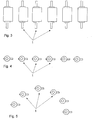
- variable guide vanes 1 used for this purpose are described in US Pat FIGS. 3 to 5 shown.
- variable vanes 1 may be processed simultaneously, but preferably more, for example, up to 50 variable vanes 1 are processed simultaneously.
- variable guide vanes 1 are processed simultaneously that the laser can be used continuously for processing. This means that as many variable vanes are processed simultaneously that when applying a second, third, fourth, etc. welding position, the variable vane 1 each had so much time to cool down that the heat input for the component properties is substantially harmless.
- variable guide vanes 1 By a correspondingly large number of variable guide vanes 1, the heat input per blade can thus be reduced, without the process time for the repair per blade having to be reduced.
- the laser used can be used continuously in this way.
- variable guide vanes 1 For this parallel repair of a plurality of variable guide vanes 1 are in particular line-shaped vane arrangements like in the FIG. 4 and / or arcuate vane arrangements as in FIG. 5 advantageous.
- a defined gas environment This gas environment is preferably as non-reactive bez. oxidizing gas carried out.
- argon and helium are provided.
- Chambers are provided to ensure the defined gas environment of the welding process. This chamber is preferably designed to be linear or annular in order to be able to realize a movement within the chamber that can be realized by a linear or rotary axis with a small chamber volume.
Landscapes
- Engineering & Computer Science (AREA)
- Mechanical Engineering (AREA)
- Physics & Mathematics (AREA)
- Optics & Photonics (AREA)
- General Engineering & Computer Science (AREA)
- Plasma & Fusion (AREA)
- Laser Beam Processing (AREA)
- Turbine Rotor Nozzle Sealing (AREA)
- Coating By Spraying Or Casting (AREA)
Claims (11)
- Procédé pour réparer une aube directrice (1) variable pour une turbine à gaz, du matériau supplémentaire étant, au cours du procédé, appliqué sur l'aube directrice (1) variable par une application de matériau, l'application de matériau étant effectuée par soudage de rechargement par rayon laser, le matériau supplémentaire étant pulvérulent, caractérisé en ce que les dimensions de grains de poudre du matériau supplémentaire s'inscrivent dans une plage de 5 à 150 µm, plusieurs couches de matériau étant appliquées successivement sur l'aube directrice (1) variable, et au moins une couche de matériau étant appliquée sur au moins une autre aube directrice (1) variable entre l'application de deux couches de matériau sur l'aube directrice (1) variable.
- Procédé selon la revendication 1, caractérisé en ce que l'application de matériau comprend l'application d'une matière résistant à l'usure.
- Procédé selon l'une des revendications précédentes, caractérisé en ce que l'application de matériau s'effectue sur la plateforme (3, 5) intérieure et extérieure de l'aube directrice (1) variable.
- Procédé selon l'une des revendications précédentes, caractérisé en ce que l'application de matériau s'effectue sur le tourillon (2, 6) intérieur et/ou extérieur de l'aube directrice (1) variable.
- Procédé selon l'une des revendications précédentes, caractérisé en ce que l'application de matériau comprend l'application de stellite ou de nitrure, de préférence de nitrure de titane, de nitrure de chrome et/ou de nitrure de bore.
- Procédé selon l'une des revendications précédentes, caractérisé en ce que l'application de matériau comprend l'application de couches de composite de matériaux durs contenant des carbures, de préférence du carbure de tungstène ou du carbure de titane.
- Procédé selon l'une des revendications précédentes, caractérisé en ce que, entre l'application de deux couches de matériau sur l'aube directrice (1) variable, au moins une couche de matériau est appliquée sur au moins deux autres aubes directrices (1) variables.
- Procédé selon l'une des revendications précédentes, caractérisé en ce que, au cours du procédé, une liaison métallurgique est constituée entre l'aube directrice (1) variable et le matériau supplémentaire appliqué.
- Procédé selon l'une des revendications précédentes, caractérisé en ce que le matériau supplémentaire est pulvérulent, de préférence avec des dimensions de grains de poudre dans une plage de 40 à 150 µm, plus préférablement de 50 à 75 µm.
- Procédé selon l'une des revendications précédentes, caractérisé en ce que l'aube directrice (1) variable est traitée dans une atmosphère inerte.
- Procédé selon la revendication 10, caractérisé en ce qu'au moins deux autres aubes directrices (1) variables sont tenues à disposition pour le traitement dans l'atmosphère inerte.
Applications Claiming Priority (2)
| Application Number | Priority Date | Filing Date | Title |
|---|---|---|---|
| DE102011087665A DE102011087665A1 (de) | 2011-12-02 | 2011-12-02 | Verfahren zur Reparatur einer variablen Leitschaufel und entsprechend reparierte Leitschaufel |
| PCT/EP2012/004913 WO2013079193A1 (fr) | 2011-12-02 | 2012-11-28 | Procédé pour réparer une aube directrice variable et aube directrice ainsi réparée |
Publications (2)
| Publication Number | Publication Date |
|---|---|
| EP2785491A1 EP2785491A1 (fr) | 2014-10-08 |
| EP2785491B1 true EP2785491B1 (fr) | 2019-05-22 |
Family
ID=47297095
Family Applications (1)
| Application Number | Title | Priority Date | Filing Date |
|---|---|---|---|
| EP12797709.8A Active EP2785491B1 (fr) | 2011-12-02 | 2012-11-28 | Procédé pour réparer une aube directrice variable |
Country Status (5)
| Country | Link |
|---|---|
| EP (1) | EP2785491B1 (fr) |
| DE (1) | DE102011087665A1 (fr) |
| MY (1) | MY184078A (fr) |
| SG (1) | SG11201402534WA (fr) |
| WO (1) | WO2013079193A1 (fr) |
Cited By (1)
| Publication number | Priority date | Publication date | Assignee | Title |
|---|---|---|---|---|
| US11661861B2 (en) | 2021-03-03 | 2023-05-30 | Garrett Transportation I Inc. | Bi-metal variable geometry turbocharger vanes and methods for manufacturing the same using laser cladding |
Families Citing this family (3)
| Publication number | Priority date | Publication date | Assignee | Title |
|---|---|---|---|---|
| EP2815839A1 (fr) * | 2013-06-21 | 2014-12-24 | Siemens Aktiengesellschaft | Procédé de réparation d'une aube de turbine |
| CN111889958B (zh) * | 2020-07-30 | 2022-06-21 | 东芝水电设备(杭州)有限公司 | 一种水轮机活动导叶磨蚀修复方法 |
| US11845138B2 (en) | 2021-03-02 | 2023-12-19 | Rtx Corporation | Systems and methods for case repair |
Citations (1)
| Publication number | Priority date | Publication date | Assignee | Title |
|---|---|---|---|---|
| DE4415783A1 (de) * | 1994-02-04 | 1995-08-10 | Ruediger Prof Dr Ing Rothe | Verfahren zur Freiformherstellung von Werkstücken |
Family Cites Families (8)
| Publication number | Priority date | Publication date | Assignee | Title |
|---|---|---|---|---|
| US6172327B1 (en) * | 1998-07-14 | 2001-01-09 | General Electric Company | Method for laser twist welding of compressor blisk airfoils |
| ITMI20022056A1 (it) * | 2002-09-27 | 2004-03-28 | Nuovo Pignone Spa | Lega a base cobalto per il rivestimento di organi soggetti ad erosione da liquido. |
| DE102004059904A1 (de) * | 2004-12-13 | 2006-06-14 | Alstom Technology Ltd | Laufschaufel für eine Turbomaschine sowie Verfahren zu deren Herstellung |
| FR2881146B1 (fr) * | 2005-01-27 | 2007-10-19 | Snecma Moteurs Sa | Procede de reparation d'une surface de frottement d'une aube a calage variable de turbomachine |
| EP1927670A1 (fr) * | 2006-11-29 | 2008-06-04 | General Electric Company | Revêtements résistant à l'usure |
| DE102009004661A1 (de) * | 2009-01-12 | 2010-07-15 | Rolls-Royce Deutschland Ltd & Co Kg | Vorrichtung zur Reparatur der Schaufeln von BLISK-Trommeln mittels Laserstrahlauftragsschweißen |
| DE102009016260A1 (de) * | 2009-04-03 | 2010-10-07 | Fraunhofer-Gesellschaft zur Förderung der angewandten Forschung e.V. | Verfahren beim Schweißen und Bauteil |
| CN101629289A (zh) * | 2009-07-22 | 2010-01-20 | 岳阳大陆激光技术有限公司 | 一种水轮机组活动导叶轴颈激光防腐耐磨工艺 |
-
2011
- 2011-12-02 DE DE102011087665A patent/DE102011087665A1/de not_active Ceased
-
2012
- 2012-11-28 WO PCT/EP2012/004913 patent/WO2013079193A1/fr not_active Ceased
- 2012-11-28 EP EP12797709.8A patent/EP2785491B1/fr active Active
- 2012-11-28 MY MYPI2014001428A patent/MY184078A/en unknown
- 2012-11-28 SG SG11201402534WA patent/SG11201402534WA/en unknown
Patent Citations (1)
| Publication number | Priority date | Publication date | Assignee | Title |
|---|---|---|---|---|
| DE4415783A1 (de) * | 1994-02-04 | 1995-08-10 | Ruediger Prof Dr Ing Rothe | Verfahren zur Freiformherstellung von Werkstücken |
Cited By (1)
| Publication number | Priority date | Publication date | Assignee | Title |
|---|---|---|---|---|
| US11661861B2 (en) | 2021-03-03 | 2023-05-30 | Garrett Transportation I Inc. | Bi-metal variable geometry turbocharger vanes and methods for manufacturing the same using laser cladding |
Also Published As
| Publication number | Publication date |
|---|---|
| SG11201402534WA (en) | 2014-09-26 |
| EP2785491A1 (fr) | 2014-10-08 |
| WO2013079193A1 (fr) | 2013-06-06 |
| DE102011087665A1 (de) | 2013-06-06 |
| MY184078A (en) | 2021-03-17 |
Similar Documents
| Publication | Publication Date | Title |
|---|---|---|
| EP2317078B1 (fr) | Aube de turbine abrasive monocristalline | |
| EP2780552B1 (fr) | Blindage d'ailettes d'étanchéité d'aubes en tial par dépôt de particules de matériau dur par brasage par induction | |
| EP2560789B1 (fr) | Procédé de traitement d'une surface d'un composant | |
| EP2590773A2 (fr) | PROCÉDÉ ET DISPOSITIF D'APPLICATION DE COUCHES DE MATÉRIAU SUR UNE PIÈCE EN TiAl | |
| DE102009037894A1 (de) | Dünnwandiges Strukturbauteil und Verfahren zu seiner Herstellung | |
| EP2582486B1 (fr) | Procédé de réparation de pales de rotor | |
| EP4063532A1 (fr) | Gros moteur doté d'une pièce de machine appartenant à un accouplement coulissant, ainsi que pièce de machine et son procédé de fabrication | |
| EP2785491B1 (fr) | Procédé pour réparer une aube directrice variable | |
| EP2294249A1 (fr) | Procédé et dispositif de pulvérisation gazeuse à froid | |
| EP2422051A2 (fr) | Procédé de production d'un revêtement dur d'un bout d'aube de turbine à gaz et aube de turbine à gaz | |
| DE102009036343A1 (de) | Anti-Frettingschicht und Verfahren zu ihrer Abscheidung | |
| EP2062997A2 (fr) | Procédé destiné à revêtir des composants | |
| DE102010001413B4 (de) | Verfahren zur Reparatur von Labyrinth-Dichtungsstegen | |
| DE10319020B4 (de) | Verfahren zum Verrunden von Kanten an Schaufeln von Turbomaschinen | |
| EP2714963B1 (fr) | Procédé d'injection de gaz froid présentant une meilleure adhérence et une porosité de couche réduite | |
| EP2014415B1 (fr) | Procédé de traitement d'une surface d'un composant d'un turbine à gas | |
| EP1816235B1 (fr) | Procédé de réparation de défauts dans des pièces coulées | |
| DE102005007404B3 (de) | Verbindung einer Welle mit einem Turbinenrad eines Abgasturboladers | |
| EP4459150A1 (fr) | Corps de frein pour un véhicule automobile et procédé de fabrication d'un corps de frein | |
| EP3222812A1 (fr) | Procede de fabrication ou de reparation d'une aube directrice, aube directrice, procede de fabrication ou de reparation d'un boitier d'une turbomachine et boitier | |
| EP4638980A2 (fr) | Procédé de production d'un corps de frein et corps de frein | |
| EP2503026A1 (fr) | Procédé de réparation d'une couche sur un substrat | |
| DE19615245C2 (de) | Verfahren und Vorrichtung zur Beschichtung von einem mit spurkranzversehenen Schienenfahrzeugmetallrades | |
| DE102008036450A1 (de) | Labyrinth-Dichtungssteg-Reparaturverfahren für Gasturbinen | |
| DE102008027491B4 (de) | Kraftfahrzeug-Achs- oder Fahrwerksbauteil |
Legal Events
| Date | Code | Title | Description |
|---|---|---|---|
| PUAI | Public reference made under article 153(3) epc to a published international application that has entered the european phase |
Free format text: ORIGINAL CODE: 0009012 |
|
| 17P | Request for examination filed |
Effective date: 20140617 |
|
| AK | Designated contracting states |
Kind code of ref document: A1 Designated state(s): AL AT BE BG CH CY CZ DE DK EE ES FI FR GB GR HR HU IE IS IT LI LT LU LV MC MK MT NL NO PL PT RO RS SE SI SK SM TR |
|
| DAX | Request for extension of the european patent (deleted) | ||
| STAA | Information on the status of an ep patent application or granted ep patent |
Free format text: STATUS: EXAMINATION IS IN PROGRESS |
|
| 17Q | First examination report despatched |
Effective date: 20180315 |
|
| GRAP | Despatch of communication of intention to grant a patent |
Free format text: ORIGINAL CODE: EPIDOSNIGR1 |
|
| STAA | Information on the status of an ep patent application or granted ep patent |
Free format text: STATUS: GRANT OF PATENT IS INTENDED |
|
| RIC1 | Information provided on ipc code assigned before grant |
Ipc: B23K 35/02 20060101ALI20181126BHEP Ipc: B23K 26/32 20140101ALI20181126BHEP Ipc: B23K 35/30 20060101ALI20181126BHEP Ipc: F01D 5/00 20060101ALI20181126BHEP Ipc: F01D 17/16 20060101ALI20181126BHEP Ipc: B23K 26/342 20140101ALI20181126BHEP Ipc: F04D 29/62 20060101ALI20181126BHEP Ipc: F04D 29/56 20060101ALI20181126BHEP Ipc: B23P 6/00 20060101AFI20181126BHEP |
|
| INTG | Intention to grant announced |
Effective date: 20181212 |
|
| GRAS | Grant fee paid |
Free format text: ORIGINAL CODE: EPIDOSNIGR3 |
|
| GRAA | (expected) grant |
Free format text: ORIGINAL CODE: 0009210 |
|
| STAA | Information on the status of an ep patent application or granted ep patent |
Free format text: STATUS: THE PATENT HAS BEEN GRANTED |
|
| AK | Designated contracting states |
Kind code of ref document: B1 Designated state(s): AL AT BE BG CH CY CZ DE DK EE ES FI FR GB GR HR HU IE IS IT LI LT LU LV MC MK MT NL NO PL PT RO RS SE SI SK SM TR |
|
| REG | Reference to a national code |
Ref country code: GB Ref legal event code: FG4D Free format text: NOT ENGLISH |
|
| REG | Reference to a national code |
Ref country code: CH Ref legal event code: EP |
|
| REG | Reference to a national code |
Ref country code: IE Ref legal event code: FG4D Free format text: LANGUAGE OF EP DOCUMENT: GERMAN |
|
| REG | Reference to a national code |
Ref country code: DE Ref legal event code: R096 Ref document number: 502012014829 Country of ref document: DE |
|
| REG | Reference to a national code |
Ref country code: AT Ref legal event code: REF Ref document number: 1135518 Country of ref document: AT Kind code of ref document: T Effective date: 20190615 |
|
| REG | Reference to a national code |
Ref country code: NL Ref legal event code: MP Effective date: 20190522 |
|
| REG | Reference to a national code |
Ref country code: LT Ref legal event code: MG4D |
|
| PG25 | Lapsed in a contracting state [announced via postgrant information from national office to epo] |
Ref country code: NO Free format text: LAPSE BECAUSE OF FAILURE TO SUBMIT A TRANSLATION OF THE DESCRIPTION OR TO PAY THE FEE WITHIN THE PRESCRIBED TIME-LIMIT Effective date: 20190822 Ref country code: FI Free format text: LAPSE BECAUSE OF FAILURE TO SUBMIT A TRANSLATION OF THE DESCRIPTION OR TO PAY THE FEE WITHIN THE PRESCRIBED TIME-LIMIT Effective date: 20190522 Ref country code: LT Free format text: LAPSE BECAUSE OF FAILURE TO SUBMIT A TRANSLATION OF THE DESCRIPTION OR TO PAY THE FEE WITHIN THE PRESCRIBED TIME-LIMIT Effective date: 20190522 Ref country code: HR Free format text: LAPSE BECAUSE OF FAILURE TO SUBMIT A TRANSLATION OF THE DESCRIPTION OR TO PAY THE FEE WITHIN THE PRESCRIBED TIME-LIMIT Effective date: 20190522 Ref country code: SE Free format text: LAPSE BECAUSE OF FAILURE TO SUBMIT A TRANSLATION OF THE DESCRIPTION OR TO PAY THE FEE WITHIN THE PRESCRIBED TIME-LIMIT Effective date: 20190522 Ref country code: PT Free format text: LAPSE BECAUSE OF FAILURE TO SUBMIT A TRANSLATION OF THE DESCRIPTION OR TO PAY THE FEE WITHIN THE PRESCRIBED TIME-LIMIT Effective date: 20190922 Ref country code: AL Free format text: LAPSE BECAUSE OF FAILURE TO SUBMIT A TRANSLATION OF THE DESCRIPTION OR TO PAY THE FEE WITHIN THE PRESCRIBED TIME-LIMIT Effective date: 20190522 Ref country code: ES Free format text: LAPSE BECAUSE OF FAILURE TO SUBMIT A TRANSLATION OF THE DESCRIPTION OR TO PAY THE FEE WITHIN THE PRESCRIBED TIME-LIMIT Effective date: 20190522 Ref country code: NL Free format text: LAPSE BECAUSE OF FAILURE TO SUBMIT A TRANSLATION OF THE DESCRIPTION OR TO PAY THE FEE WITHIN THE PRESCRIBED TIME-LIMIT Effective date: 20190522 |
|
| PG25 | Lapsed in a contracting state [announced via postgrant information from national office to epo] |
Ref country code: BG Free format text: LAPSE BECAUSE OF FAILURE TO SUBMIT A TRANSLATION OF THE DESCRIPTION OR TO PAY THE FEE WITHIN THE PRESCRIBED TIME-LIMIT Effective date: 20190822 Ref country code: RS Free format text: LAPSE BECAUSE OF FAILURE TO SUBMIT A TRANSLATION OF THE DESCRIPTION OR TO PAY THE FEE WITHIN THE PRESCRIBED TIME-LIMIT Effective date: 20190522 Ref country code: LV Free format text: LAPSE BECAUSE OF FAILURE TO SUBMIT A TRANSLATION OF THE DESCRIPTION OR TO PAY THE FEE WITHIN THE PRESCRIBED TIME-LIMIT Effective date: 20190522 Ref country code: GR Free format text: LAPSE BECAUSE OF FAILURE TO SUBMIT A TRANSLATION OF THE DESCRIPTION OR TO PAY THE FEE WITHIN THE PRESCRIBED TIME-LIMIT Effective date: 20190823 |
|
| PG25 | Lapsed in a contracting state [announced via postgrant information from national office to epo] |
Ref country code: SK Free format text: LAPSE BECAUSE OF FAILURE TO SUBMIT A TRANSLATION OF THE DESCRIPTION OR TO PAY THE FEE WITHIN THE PRESCRIBED TIME-LIMIT Effective date: 20190522 Ref country code: RO Free format text: LAPSE BECAUSE OF FAILURE TO SUBMIT A TRANSLATION OF THE DESCRIPTION OR TO PAY THE FEE WITHIN THE PRESCRIBED TIME-LIMIT Effective date: 20190522 Ref country code: EE Free format text: LAPSE BECAUSE OF FAILURE TO SUBMIT A TRANSLATION OF THE DESCRIPTION OR TO PAY THE FEE WITHIN THE PRESCRIBED TIME-LIMIT Effective date: 20190522 Ref country code: DK Free format text: LAPSE BECAUSE OF FAILURE TO SUBMIT A TRANSLATION OF THE DESCRIPTION OR TO PAY THE FEE WITHIN THE PRESCRIBED TIME-LIMIT Effective date: 20190522 Ref country code: CZ Free format text: LAPSE BECAUSE OF FAILURE TO SUBMIT A TRANSLATION OF THE DESCRIPTION OR TO PAY THE FEE WITHIN THE PRESCRIBED TIME-LIMIT Effective date: 20190522 |
|
| REG | Reference to a national code |
Ref country code: DE Ref legal event code: R097 Ref document number: 502012014829 Country of ref document: DE |
|
| PG25 | Lapsed in a contracting state [announced via postgrant information from national office to epo] |
Ref country code: SM Free format text: LAPSE BECAUSE OF FAILURE TO SUBMIT A TRANSLATION OF THE DESCRIPTION OR TO PAY THE FEE WITHIN THE PRESCRIBED TIME-LIMIT Effective date: 20190522 Ref country code: IT Free format text: LAPSE BECAUSE OF FAILURE TO SUBMIT A TRANSLATION OF THE DESCRIPTION OR TO PAY THE FEE WITHIN THE PRESCRIBED TIME-LIMIT Effective date: 20190522 |
|
| PLBE | No opposition filed within time limit |
Free format text: ORIGINAL CODE: 0009261 |
|
| STAA | Information on the status of an ep patent application or granted ep patent |
Free format text: STATUS: NO OPPOSITION FILED WITHIN TIME LIMIT |
|
| PG25 | Lapsed in a contracting state [announced via postgrant information from national office to epo] |
Ref country code: TR Free format text: LAPSE BECAUSE OF FAILURE TO SUBMIT A TRANSLATION OF THE DESCRIPTION OR TO PAY THE FEE WITHIN THE PRESCRIBED TIME-LIMIT Effective date: 20190522 |
|
| 26N | No opposition filed |
Effective date: 20200225 |
|
| PG25 | Lapsed in a contracting state [announced via postgrant information from national office to epo] |
Ref country code: PL Free format text: LAPSE BECAUSE OF FAILURE TO SUBMIT A TRANSLATION OF THE DESCRIPTION OR TO PAY THE FEE WITHIN THE PRESCRIBED TIME-LIMIT Effective date: 20190522 |
|
| PG25 | Lapsed in a contracting state [announced via postgrant information from national office to epo] |
Ref country code: SI Free format text: LAPSE BECAUSE OF FAILURE TO SUBMIT A TRANSLATION OF THE DESCRIPTION OR TO PAY THE FEE WITHIN THE PRESCRIBED TIME-LIMIT Effective date: 20190522 |
|
| REG | Reference to a national code |
Ref country code: CH Ref legal event code: PL |
|
| PG25 | Lapsed in a contracting state [announced via postgrant information from national office to epo] |
Ref country code: MC Free format text: LAPSE BECAUSE OF FAILURE TO SUBMIT A TRANSLATION OF THE DESCRIPTION OR TO PAY THE FEE WITHIN THE PRESCRIBED TIME-LIMIT Effective date: 20190522 Ref country code: CH Free format text: LAPSE BECAUSE OF NON-PAYMENT OF DUE FEES Effective date: 20191130 Ref country code: LU Free format text: LAPSE BECAUSE OF NON-PAYMENT OF DUE FEES Effective date: 20191128 Ref country code: LI Free format text: LAPSE BECAUSE OF NON-PAYMENT OF DUE FEES Effective date: 20191130 |
|
| REG | Reference to a national code |
Ref country code: BE Ref legal event code: MM Effective date: 20191130 |
|
| PG25 | Lapsed in a contracting state [announced via postgrant information from national office to epo] |
Ref country code: IE Free format text: LAPSE BECAUSE OF NON-PAYMENT OF DUE FEES Effective date: 20191128 |
|
| PG25 | Lapsed in a contracting state [announced via postgrant information from national office to epo] |
Ref country code: BE Free format text: LAPSE BECAUSE OF NON-PAYMENT OF DUE FEES Effective date: 20191130 |
|
| REG | Reference to a national code |
Ref country code: AT Ref legal event code: MM01 Ref document number: 1135518 Country of ref document: AT Kind code of ref document: T Effective date: 20191128 |
|
| PG25 | Lapsed in a contracting state [announced via postgrant information from national office to epo] |
Ref country code: AT Free format text: LAPSE BECAUSE OF NON-PAYMENT OF DUE FEES Effective date: 20191128 |
|
| PG25 | Lapsed in a contracting state [announced via postgrant information from national office to epo] |
Ref country code: CY Free format text: LAPSE BECAUSE OF FAILURE TO SUBMIT A TRANSLATION OF THE DESCRIPTION OR TO PAY THE FEE WITHIN THE PRESCRIBED TIME-LIMIT Effective date: 20190522 |
|
| PG25 | Lapsed in a contracting state [announced via postgrant information from national office to epo] |
Ref country code: IS Free format text: LAPSE BECAUSE OF FAILURE TO SUBMIT A TRANSLATION OF THE DESCRIPTION OR TO PAY THE FEE WITHIN THE PRESCRIBED TIME-LIMIT Effective date: 20190922 |
|
| PG25 | Lapsed in a contracting state [announced via postgrant information from national office to epo] |
Ref country code: MT Free format text: LAPSE BECAUSE OF FAILURE TO SUBMIT A TRANSLATION OF THE DESCRIPTION OR TO PAY THE FEE WITHIN THE PRESCRIBED TIME-LIMIT Effective date: 20190522 Ref country code: HU Free format text: LAPSE BECAUSE OF FAILURE TO SUBMIT A TRANSLATION OF THE DESCRIPTION OR TO PAY THE FEE WITHIN THE PRESCRIBED TIME-LIMIT; INVALID AB INITIO Effective date: 20121128 |
|
| PG25 | Lapsed in a contracting state [announced via postgrant information from national office to epo] |
Ref country code: MK Free format text: LAPSE BECAUSE OF FAILURE TO SUBMIT A TRANSLATION OF THE DESCRIPTION OR TO PAY THE FEE WITHIN THE PRESCRIBED TIME-LIMIT Effective date: 20190522 |
|
| PGFP | Annual fee paid to national office [announced via postgrant information from national office to epo] |
Ref country code: GB Payment date: 20221123 Year of fee payment: 11 Ref country code: FR Payment date: 20221118 Year of fee payment: 11 |
|
| P01 | Opt-out of the competence of the unified patent court (upc) registered |
Effective date: 20230524 |
|
| GBPC | Gb: european patent ceased through non-payment of renewal fee |
Effective date: 20231128 |
|
| PG25 | Lapsed in a contracting state [announced via postgrant information from national office to epo] |
Ref country code: GB Free format text: LAPSE BECAUSE OF NON-PAYMENT OF DUE FEES Effective date: 20231128 |
|
| PG25 | Lapsed in a contracting state [announced via postgrant information from national office to epo] |
Ref country code: FR Free format text: LAPSE BECAUSE OF NON-PAYMENT OF DUE FEES Effective date: 20231130 |
|
| PG25 | Lapsed in a contracting state [announced via postgrant information from national office to epo] |
Ref country code: GB Free format text: LAPSE BECAUSE OF NON-PAYMENT OF DUE FEES Effective date: 20231128 Ref country code: FR Free format text: LAPSE BECAUSE OF NON-PAYMENT OF DUE FEES Effective date: 20231130 |
|
| PGFP | Annual fee paid to national office [announced via postgrant information from national office to epo] |
Ref country code: DE Payment date: 20251118 Year of fee payment: 14 |