EP2785507B1 - Ligne d'embouteillage et procédé - Google Patents
Ligne d'embouteillage et procédé Download PDFInfo
- Publication number
- EP2785507B1 EP2785507B1 EP12813511.8A EP12813511A EP2785507B1 EP 2785507 B1 EP2785507 B1 EP 2785507B1 EP 12813511 A EP12813511 A EP 12813511A EP 2785507 B1 EP2785507 B1 EP 2785507B1
- Authority
- EP
- European Patent Office
- Prior art keywords
- unit
- moulding
- storage system
- warehouse
- parisons
- Prior art date
- Legal status (The legal status is an assumption and is not a legal conclusion. Google has not performed a legal analysis and makes no representation as to the accuracy of the status listed.)
- Active
Links
Images



Classifications
-
- B—PERFORMING OPERATIONS; TRANSPORTING
- B67—OPENING, CLOSING OR CLEANING BOTTLES, JARS OR SIMILAR CONTAINERS; LIQUID HANDLING
- B67C—CLEANING, FILLING WITH LIQUIDS OR SEMILIQUIDS, OR EMPTYING, OF BOTTLES, JARS, CANS, CASKS, BARRELS, OR SIMILAR CONTAINERS, NOT OTHERWISE PROVIDED FOR; FUNNELS
- B67C7/00—Concurrent cleaning, filling, and closing of bottles; Processes or devices for at least two of these operations
- B67C7/0073—Sterilising, aseptic filling and closing
-
- B—PERFORMING OPERATIONS; TRANSPORTING
- B29—WORKING OF PLASTICS; WORKING OF SUBSTANCES IN A PLASTIC STATE IN GENERAL
- B29C—SHAPING OR JOINING OF PLASTICS; SHAPING OF MATERIAL IN A PLASTIC STATE, NOT OTHERWISE PROVIDED FOR; AFTER-TREATMENT OF THE SHAPED PRODUCTS, e.g. REPAIRING
- B29C49/00—Blow-moulding, i.e. blowing a preform or parison to a desired shape within a mould; Apparatus therefor
- B29C49/02—Combined blow-moulding and manufacture of the preform or the parison
- B29C49/06—Injection blow-moulding
-
- B—PERFORMING OPERATIONS; TRANSPORTING
- B29—WORKING OF PLASTICS; WORKING OF SUBSTANCES IN A PLASTIC STATE IN GENERAL
- B29C—SHAPING OR JOINING OF PLASTICS; SHAPING OF MATERIAL IN A PLASTIC STATE, NOT OTHERWISE PROVIDED FOR; AFTER-TREATMENT OF THE SHAPED PRODUCTS, e.g. REPAIRING
- B29C49/00—Blow-moulding, i.e. blowing a preform or parison to a desired shape within a mould; Apparatus therefor
- B29C49/42—Component parts, details or accessories; Auxiliary operations
- B29C49/4205—Handling means, e.g. transfer, loading or discharging means
- B29C49/42093—Transporting apparatus, e.g. slides, wheels or conveyors
- B29C49/42101—Conveyors, e.g. flat conveyor or clamping between two bands
-
- B—PERFORMING OPERATIONS; TRANSPORTING
- B29—WORKING OF PLASTICS; WORKING OF SUBSTANCES IN A PLASTIC STATE IN GENERAL
- B29C—SHAPING OR JOINING OF PLASTICS; SHAPING OF MATERIAL IN A PLASTIC STATE, NOT OTHERWISE PROVIDED FOR; AFTER-TREATMENT OF THE SHAPED PRODUCTS, e.g. REPAIRING
- B29C49/00—Blow-moulding, i.e. blowing a preform or parison to a desired shape within a mould; Apparatus therefor
- B29C49/42—Component parts, details or accessories; Auxiliary operations
- B29C49/4205—Handling means, e.g. transfer, loading or discharging means
- B29C49/42093—Transporting apparatus, e.g. slides, wheels or conveyors
- B29C49/42107—Transporting apparatus, e.g. slides, wheels or conveyors with accumulator or temporary storage, e.g. while waiting for the blowing apparatus
-
- B—PERFORMING OPERATIONS; TRANSPORTING
- B29—WORKING OF PLASTICS; WORKING OF SUBSTANCES IN A PLASTIC STATE IN GENERAL
- B29C—SHAPING OR JOINING OF PLASTICS; SHAPING OF MATERIAL IN A PLASTIC STATE, NOT OTHERWISE PROVIDED FOR; AFTER-TREATMENT OF THE SHAPED PRODUCTS, e.g. REPAIRING
- B29C49/00—Blow-moulding, i.e. blowing a preform or parison to a desired shape within a mould; Apparatus therefor
- B29C49/42—Component parts, details or accessories; Auxiliary operations
- B29C49/4273—Auxiliary operations after the blow-moulding operation not otherwise provided for
-
- B—PERFORMING OPERATIONS; TRANSPORTING
- B29—WORKING OF PLASTICS; WORKING OF SUBSTANCES IN A PLASTIC STATE IN GENERAL
- B29C—SHAPING OR JOINING OF PLASTICS; SHAPING OF MATERIAL IN A PLASTIC STATE, NOT OTHERWISE PROVIDED FOR; AFTER-TREATMENT OF THE SHAPED PRODUCTS, e.g. REPAIRING
- B29C49/00—Blow-moulding, i.e. blowing a preform or parison to a desired shape within a mould; Apparatus therefor
- B29C49/42—Component parts, details or accessories; Auxiliary operations
- B29C49/46—Component parts, details or accessories; Auxiliary operations characterised by using particular environment or blow fluids other than air
-
- B—PERFORMING OPERATIONS; TRANSPORTING
- B29—WORKING OF PLASTICS; WORKING OF SUBSTANCES IN A PLASTIC STATE IN GENERAL
- B29C—SHAPING OR JOINING OF PLASTICS; SHAPING OF MATERIAL IN A PLASTIC STATE, NOT OTHERWISE PROVIDED FOR; AFTER-TREATMENT OF THE SHAPED PRODUCTS, e.g. REPAIRING
- B29C49/00—Blow-moulding, i.e. blowing a preform or parison to a desired shape within a mould; Apparatus therefor
- B29C49/42—Component parts, details or accessories; Auxiliary operations
- B29C49/64—Heating or cooling preforms, parisons or blown articles
- B29C49/6409—Thermal conditioning of preforms
- B29C49/6418—Heating of preforms
-
- B—PERFORMING OPERATIONS; TRANSPORTING
- B29—WORKING OF PLASTICS; WORKING OF SUBSTANCES IN A PLASTIC STATE IN GENERAL
- B29C—SHAPING OR JOINING OF PLASTICS; SHAPING OF MATERIAL IN A PLASTIC STATE, NOT OTHERWISE PROVIDED FOR; AFTER-TREATMENT OF THE SHAPED PRODUCTS, e.g. REPAIRING
- B29C49/00—Blow-moulding, i.e. blowing a preform or parison to a desired shape within a mould; Apparatus therefor
- B29C49/42—Component parts, details or accessories; Auxiliary operations
- B29C49/64—Heating or cooling preforms, parisons or blown articles
- B29C49/68—Ovens specially adapted for heating preforms or parisons
- B29C49/6855—Cooling of heating means, e.g. avoiding overheating
-
- B—PERFORMING OPERATIONS; TRANSPORTING
- B65—CONVEYING; PACKING; STORING; HANDLING THIN OR FILAMENTARY MATERIAL
- B65B—MACHINES, APPARATUS OR DEVICES FOR, OR METHODS OF, PACKAGING ARTICLES OR MATERIALS; UNPACKING
- B65B3/00—Packaging plastic material, semiliquids, liquids or mixed solids and liquids, in individual containers or receptacles, e.g. bags, sacks, boxes, cartons, cans, or jars
- B65B3/02—Machines characterised by the incorporation of means for making the containers or receptacles
- B65B3/022—Making containers by moulding of a thermoplastic material
-
- B—PERFORMING OPERATIONS; TRANSPORTING
- B65—CONVEYING; PACKING; STORING; HANDLING THIN OR FILAMENTARY MATERIAL
- B65B—MACHINES, APPARATUS OR DEVICES FOR, OR METHODS OF, PACKAGING ARTICLES OR MATERIALS; UNPACKING
- B65B3/00—Packaging plastic material, semiliquids, liquids or mixed solids and liquids, in individual containers or receptacles, e.g. bags, sacks, boxes, cartons, cans, or jars
- B65B3/04—Methods of, or means for, filling the material into the containers or receptacles
-
- B—PERFORMING OPERATIONS; TRANSPORTING
- B65—CONVEYING; PACKING; STORING; HANDLING THIN OR FILAMENTARY MATERIAL
- B65B—MACHINES, APPARATUS OR DEVICES FOR, OR METHODS OF, PACKAGING ARTICLES OR MATERIALS; UNPACKING
- B65B7/00—Closing containers or receptacles after filling
- B65B7/16—Closing semi-rigid or rigid containers or receptacles not deformed by, or not taking-up shape of, contents, e.g. boxes or cartons
- B65B7/28—Closing semi-rigid or rigid containers or receptacles not deformed by, or not taking-up shape of, contents, e.g. boxes or cartons by applying separate preformed closures, e.g. lids, covers
-
- B—PERFORMING OPERATIONS; TRANSPORTING
- B65—CONVEYING; PACKING; STORING; HANDLING THIN OR FILAMENTARY MATERIAL
- B65G—TRANSPORT OR STORAGE DEVICES, e.g. CONVEYORS FOR LOADING OR TIPPING, SHOP CONVEYOR SYSTEMS OR PNEUMATIC TUBE CONVEYORS
- B65G1/00—Storing articles, individually or in orderly arrangement, in warehouses or magazines
- B65G1/02—Storage devices
- B65G1/04—Storage devices mechanical
- B65G1/06—Storage devices mechanical with means for presenting articles for removal at predetermined position or level
-
- B—PERFORMING OPERATIONS; TRANSPORTING
- B65—CONVEYING; PACKING; STORING; HANDLING THIN OR FILAMENTARY MATERIAL
- B65G—TRANSPORT OR STORAGE DEVICES, e.g. CONVEYORS FOR LOADING OR TIPPING, SHOP CONVEYOR SYSTEMS OR PNEUMATIC TUBE CONVEYORS
- B65G37/00—Combinations of mechanical conveyors of the same kind, or of different kinds, of interest apart from their application in particular machines or use in particular manufacturing processes
-
- B—PERFORMING OPERATIONS; TRANSPORTING
- B65—CONVEYING; PACKING; STORING; HANDLING THIN OR FILAMENTARY MATERIAL
- B65G—TRANSPORT OR STORAGE DEVICES, e.g. CONVEYORS FOR LOADING OR TIPPING, SHOP CONVEYOR SYSTEMS OR PNEUMATIC TUBE CONVEYORS
- B65G47/00—Article or material-handling devices associated with conveyors; Methods employing such devices
-
- B—PERFORMING OPERATIONS; TRANSPORTING
- B65—CONVEYING; PACKING; STORING; HANDLING THIN OR FILAMENTARY MATERIAL
- B65G—TRANSPORT OR STORAGE DEVICES, e.g. CONVEYORS FOR LOADING OR TIPPING, SHOP CONVEYOR SYSTEMS OR PNEUMATIC TUBE CONVEYORS
- B65G65/00—Loading or unloading
-
- B—PERFORMING OPERATIONS; TRANSPORTING
- B65—CONVEYING; PACKING; STORING; HANDLING THIN OR FILAMENTARY MATERIAL
- B65G—TRANSPORT OR STORAGE DEVICES, e.g. CONVEYORS FOR LOADING OR TIPPING, SHOP CONVEYOR SYSTEMS OR PNEUMATIC TUBE CONVEYORS
- B65G65/00—Loading or unloading
- B65G65/23—Devices for tilting and emptying of containers
-
- B—PERFORMING OPERATIONS; TRANSPORTING
- B67—OPENING, CLOSING OR CLEANING BOTTLES, JARS OR SIMILAR CONTAINERS; LIQUID HANDLING
- B67C—CLEANING, FILLING WITH LIQUIDS OR SEMILIQUIDS, OR EMPTYING, OF BOTTLES, JARS, CANS, CASKS, BARRELS, OR SIMILAR CONTAINERS, NOT OTHERWISE PROVIDED FOR; FUNNELS
- B67C7/00—Concurrent cleaning, filling, and closing of bottles; Processes or devices for at least two of these operations
- B67C7/0006—Conveying; Synchronising
- B67C7/002—General lay-out of bottle-handling machines
-
- B—PERFORMING OPERATIONS; TRANSPORTING
- B29—WORKING OF PLASTICS; WORKING OF SUBSTANCES IN A PLASTIC STATE IN GENERAL
- B29C—SHAPING OR JOINING OF PLASTICS; SHAPING OF MATERIAL IN A PLASTIC STATE, NOT OTHERWISE PROVIDED FOR; AFTER-TREATMENT OF THE SHAPED PRODUCTS, e.g. REPAIRING
- B29C49/00—Blow-moulding, i.e. blowing a preform or parison to a desired shape within a mould; Apparatus therefor
- B29C49/02—Combined blow-moulding and manufacture of the preform or the parison
- B29C2049/023—Combined blow-moulding and manufacture of the preform or the parison using inherent heat of the preform, i.e. 1 step blow moulding
-
- B—PERFORMING OPERATIONS; TRANSPORTING
- B29—WORKING OF PLASTICS; WORKING OF SUBSTANCES IN A PLASTIC STATE IN GENERAL
- B29C—SHAPING OR JOINING OF PLASTICS; SHAPING OF MATERIAL IN A PLASTIC STATE, NOT OTHERWISE PROVIDED FOR; AFTER-TREATMENT OF THE SHAPED PRODUCTS, e.g. REPAIRING
- B29C49/00—Blow-moulding, i.e. blowing a preform or parison to a desired shape within a mould; Apparatus therefor
- B29C49/42—Component parts, details or accessories; Auxiliary operations
- B29C49/46—Component parts, details or accessories; Auxiliary operations characterised by using particular environment or blow fluids other than air
- B29C2049/4673—Environments
- B29C2049/4697—Clean room
-
- B—PERFORMING OPERATIONS; TRANSPORTING
- B29—WORKING OF PLASTICS; WORKING OF SUBSTANCES IN A PLASTIC STATE IN GENERAL
- B29C—SHAPING OR JOINING OF PLASTICS; SHAPING OF MATERIAL IN A PLASTIC STATE, NOT OTHERWISE PROVIDED FOR; AFTER-TREATMENT OF THE SHAPED PRODUCTS, e.g. REPAIRING
- B29C49/00—Blow-moulding, i.e. blowing a preform or parison to a desired shape within a mould; Apparatus therefor
- B29C49/42—Component parts, details or accessories; Auxiliary operations
- B29C49/46—Component parts, details or accessories; Auxiliary operations characterised by using particular environment or blow fluids other than air
- B29C2049/4673—Environments
- B29C2049/4698—Pressure difference, e.g. over pressure in room
-
- B—PERFORMING OPERATIONS; TRANSPORTING
- B29—WORKING OF PLASTICS; WORKING OF SUBSTANCES IN A PLASTIC STATE IN GENERAL
- B29C—SHAPING OR JOINING OF PLASTICS; SHAPING OF MATERIAL IN A PLASTIC STATE, NOT OTHERWISE PROVIDED FOR; AFTER-TREATMENT OF THE SHAPED PRODUCTS, e.g. REPAIRING
- B29C49/00—Blow-moulding, i.e. blowing a preform or parison to a desired shape within a mould; Apparatus therefor
- B29C49/42—Component parts, details or accessories; Auxiliary operations
- B29C49/78—Measuring, controlling or regulating
- B29C2049/7878—Preform or article handling, e.g. flow from station to station
-
- B—PERFORMING OPERATIONS; TRANSPORTING
- B29—WORKING OF PLASTICS; WORKING OF SUBSTANCES IN A PLASTIC STATE IN GENERAL
- B29C—SHAPING OR JOINING OF PLASTICS; SHAPING OF MATERIAL IN A PLASTIC STATE, NOT OTHERWISE PROVIDED FOR; AFTER-TREATMENT OF THE SHAPED PRODUCTS, e.g. REPAIRING
- B29C49/00—Blow-moulding, i.e. blowing a preform or parison to a desired shape within a mould; Apparatus therefor
- B29C49/02—Combined blow-moulding and manufacture of the preform or the parison
- B29C49/0685—Compression blow-moulding
-
- B—PERFORMING OPERATIONS; TRANSPORTING
- B29—WORKING OF PLASTICS; WORKING OF SUBSTANCES IN A PLASTIC STATE IN GENERAL
- B29C—SHAPING OR JOINING OF PLASTICS; SHAPING OF MATERIAL IN A PLASTIC STATE, NOT OTHERWISE PROVIDED FOR; AFTER-TREATMENT OF THE SHAPED PRODUCTS, e.g. REPAIRING
- B29C49/00—Blow-moulding, i.e. blowing a preform or parison to a desired shape within a mould; Apparatus therefor
- B29C49/28—Blow-moulding apparatus
- B29C49/30—Blow-moulding apparatus having movable moulds or mould parts
- B29C49/36—Blow-moulding apparatus having movable moulds or mould parts rotatable about one axis
-
- B—PERFORMING OPERATIONS; TRANSPORTING
- B29—WORKING OF PLASTICS; WORKING OF SUBSTANCES IN A PLASTIC STATE IN GENERAL
- B29C—SHAPING OR JOINING OF PLASTICS; SHAPING OF MATERIAL IN A PLASTIC STATE, NOT OTHERWISE PROVIDED FOR; AFTER-TREATMENT OF THE SHAPED PRODUCTS, e.g. REPAIRING
- B29C49/00—Blow-moulding, i.e. blowing a preform or parison to a desired shape within a mould; Apparatus therefor
- B29C49/42—Component parts, details or accessories; Auxiliary operations
- B29C49/4205—Handling means, e.g. transfer, loading or discharging means
- B29C49/42069—Means explicitly adapted for transporting blown article
-
- B—PERFORMING OPERATIONS; TRANSPORTING
- B29—WORKING OF PLASTICS; WORKING OF SUBSTANCES IN A PLASTIC STATE IN GENERAL
- B29C—SHAPING OR JOINING OF PLASTICS; SHAPING OF MATERIAL IN A PLASTIC STATE, NOT OTHERWISE PROVIDED FOR; AFTER-TREATMENT OF THE SHAPED PRODUCTS, e.g. REPAIRING
- B29C49/00—Blow-moulding, i.e. blowing a preform or parison to a desired shape within a mould; Apparatus therefor
- B29C49/42—Component parts, details or accessories; Auxiliary operations
- B29C49/4205—Handling means, e.g. transfer, loading or discharging means
- B29C49/42073—Grippers
- B29C49/42075—Grippers with pivoting clamps
-
- B—PERFORMING OPERATIONS; TRANSPORTING
- B29—WORKING OF PLASTICS; WORKING OF SUBSTANCES IN A PLASTIC STATE IN GENERAL
- B29C—SHAPING OR JOINING OF PLASTICS; SHAPING OF MATERIAL IN A PLASTIC STATE, NOT OTHERWISE PROVIDED FOR; AFTER-TREATMENT OF THE SHAPED PRODUCTS, e.g. REPAIRING
- B29C49/00—Blow-moulding, i.e. blowing a preform or parison to a desired shape within a mould; Apparatus therefor
- B29C49/42—Component parts, details or accessories; Auxiliary operations
- B29C49/4273—Auxiliary operations after the blow-moulding operation not otherwise provided for
- B29C49/428—Joining
- B29C49/42802—Joining a closure or a sealing foil to the article or pincing the opening
-
- B—PERFORMING OPERATIONS; TRANSPORTING
- B29—WORKING OF PLASTICS; WORKING OF SUBSTANCES IN A PLASTIC STATE IN GENERAL
- B29C—SHAPING OR JOINING OF PLASTICS; SHAPING OF MATERIAL IN A PLASTIC STATE, NOT OTHERWISE PROVIDED FOR; AFTER-TREATMENT OF THE SHAPED PRODUCTS, e.g. REPAIRING
- B29C49/00—Blow-moulding, i.e. blowing a preform or parison to a desired shape within a mould; Apparatus therefor
- B29C49/42—Component parts, details or accessories; Auxiliary operations
- B29C49/4273—Auxiliary operations after the blow-moulding operation not otherwise provided for
- B29C49/42808—Filling the article
-
- B—PERFORMING OPERATIONS; TRANSPORTING
- B29—WORKING OF PLASTICS; WORKING OF SUBSTANCES IN A PLASTIC STATE IN GENERAL
- B29C—SHAPING OR JOINING OF PLASTICS; SHAPING OF MATERIAL IN A PLASTIC STATE, NOT OTHERWISE PROVIDED FOR; AFTER-TREATMENT OF THE SHAPED PRODUCTS, e.g. REPAIRING
- B29C49/00—Blow-moulding, i.e. blowing a preform or parison to a desired shape within a mould; Apparatus therefor
- B29C49/42—Component parts, details or accessories; Auxiliary operations
- B29C49/64—Heating or cooling preforms, parisons or blown articles
- B29C49/6409—Thermal conditioning of preforms
- B29C49/6427—Cooling of preforms
-
- B—PERFORMING OPERATIONS; TRANSPORTING
- B29—WORKING OF PLASTICS; WORKING OF SUBSTANCES IN A PLASTIC STATE IN GENERAL
- B29K—INDEXING SCHEME ASSOCIATED WITH SUBCLASSES B29B, B29C OR B29D, RELATING TO MOULDING MATERIALS OR TO MATERIALS FOR MOULDS, REINFORCEMENTS, FILLERS OR PREFORMED PARTS, e.g. INSERTS
- B29K2105/00—Condition, form or state of moulded material or of the material to be shaped
- B29K2105/25—Solid
- B29K2105/253—Preform
- B29K2105/258—Tubular
-
- B—PERFORMING OPERATIONS; TRANSPORTING
- B29—WORKING OF PLASTICS; WORKING OF SUBSTANCES IN A PLASTIC STATE IN GENERAL
- B29L—INDEXING SCHEME ASSOCIATED WITH SUBCLASS B29C, RELATING TO PARTICULAR ARTICLES
- B29L2031/00—Other particular articles
- B29L2031/56—Stoppers or lids for bottles, jars, or the like, e.g. closures
- B29L2031/565—Stoppers or lids for bottles, jars, or the like, e.g. closures for containers
-
- B—PERFORMING OPERATIONS; TRANSPORTING
- B29—WORKING OF PLASTICS; WORKING OF SUBSTANCES IN A PLASTIC STATE IN GENERAL
- B29L—INDEXING SCHEME ASSOCIATED WITH SUBCLASS B29C, RELATING TO PARTICULAR ARTICLES
- B29L2031/00—Other particular articles
- B29L2031/712—Containers; Packaging elements or accessories, Packages
- B29L2031/7158—Bottles
-
- B—PERFORMING OPERATIONS; TRANSPORTING
- B67—OPENING, CLOSING OR CLEANING BOTTLES, JARS OR SIMILAR CONTAINERS; LIQUID HANDLING
- B67C—CLEANING, FILLING WITH LIQUIDS OR SEMILIQUIDS, OR EMPTYING, OF BOTTLES, JARS, CANS, CASKS, BARRELS, OR SIMILAR CONTAINERS, NOT OTHERWISE PROVIDED FOR; FUNNELS
- B67C3/00—Bottling liquids or semiliquids; Filling jars or cans with liquids or semiliquids using bottling or like apparatus; Filling casks or barrels with liquids or semiliquids
- B67C3/02—Bottling liquids or semiliquids; Filling jars or cans with liquids or semiliquids using bottling or like apparatus
- B67C3/22—Details
- B67C2003/227—Additional apparatus related to blow-moulding of the containers, e.g. a complete production line forming filled containers from preforms
-
- B—PERFORMING OPERATIONS; TRANSPORTING
- B67—OPENING, CLOSING OR CLEANING BOTTLES, JARS OR SIMILAR CONTAINERS; LIQUID HANDLING
- B67C—CLEANING, FILLING WITH LIQUIDS OR SEMILIQUIDS, OR EMPTYING, OF BOTTLES, JARS, CANS, CASKS, BARRELS, OR SIMILAR CONTAINERS, NOT OTHERWISE PROVIDED FOR; FUNNELS
- B67C3/00—Bottling liquids or semiliquids; Filling jars or cans with liquids or semiliquids using bottling or like apparatus; Filling casks or barrels with liquids or semiliquids
- B67C3/02—Bottling liquids or semiliquids; Filling jars or cans with liquids or semiliquids using bottling or like apparatus
- B67C3/22—Details
- B67C2003/228—Aseptic features
Definitions
- This invention relates to a continuous cycle line and method for bottling containers of thermoplastic material.
- the invention relates to a line and a method for making containers of thermoplastic material from raw plastic and filling them with liquid or semi-liquid food products.
- bottling lines comprise:
- these bottling lines have two main drawbacks: the first drawback is linked to the efficiency and reliability of the line, whilst the second drawback is linked to the need for cleanliness and hygiene during the entire process where food products are involved.
- patent WO2009127962 to the same Applicant as this invention discloses a system which comprises a parison moulding machine, an oven for the parisons and a blow-moulding machine.
- the system also comprises a cooling carousel interposed between the moulding machine and the oven, and a storage system connected to the cooling carousel and to the blow-moulding machine.
- WO 2011 148953 discloses a line and a method in accordence with the preambles of claims 1 and 10 and also enclosed connections.
- patent document IT1359024 in the name of the same Applicant as this invention, describes a storage system containing parisons and caps for feeding respective units of a bottling line.
- the interior of the storage system is kept under conditions of overpressure so as to allow storage of heterogeneous objects, that is, parisons and caps.
- patent IT1359024 fails to deal with the problem of hygiene and does not provide solutions able to guarantee the reliability and efficiency of the line.
- Moulding machines which process raw plastic (for example to mould the parisons or caps) have a high thermal inertia.
- the high thermal inertia of the moulding units has two consequences.
- the first consequence is that stopping the units too frequently can lead to problems. Indeed, the units need to be kept on all the time and the frequency of machine shutdowns must be reduced to a minimum:
- This invention has for an aim to provide a continuous cycle line and method for bottling containers of thermoplastic material which overcome the above mentioned drawbacks of the prior art.
- the aim of the invention is to provide a continuous cycle line and method for bottling containers of thermoplastic material which are particularly reliable and efficient and which, at the same time, guarantee a high level of hygiene.
- the bottling line comprises at least one moulding unit for making parisons of thermoplastic material (for example, PET) from the plastic material in its raw form (for example, pellets).
- thermoplastic material for example, PET
- the plastic material in its raw form for example, pellets
- the line also comprises a thermal conditioning unit for the parisons, configured to heat and cool the parisons.
- the thermal conditioning unit is connected to the outfeed of the parison moulding machine.
- the parison moulding machine is preferably (but not necessarily) a rotary machine.
- the machine works by compression (that is to say, the parison is obtained by compressing the plastic).
- the line comprises a blow-moulding unit configured to receive the heated parisons from the conditioning unit and to blow-mould them in such a way as to make containers (of PET) designed to be filled with liquid or semi-liquid food products (the term "semi-liquid product” is used to mean, for example, a sauce or other dense liquid, which may or may not have pieces of solid food product in it).
- parison moulding unit is preferably rotary and works by compression it may be observed that the parisons are warm or hot when they are made available for further processing.
- the conditioning unit is configured not only to heat the parison but also to cool them.
- the conditioning unit preferably comprises an oven and a cooling carousel interposed between the parison moulding unit and the oven.
- the oven may be equipped with cooling means and with a switch which can be used to change the oven between a heating configuration and a cooling configuration.
- the line also comprises a filling unit configured to receive the containers from the blow-moulding unit and to fill them with liquid food products (for example, beverages) or semi-liquid food products.
- liquid food products for example, beverages
- semi-liquid food products for example, beverages
- the line also comprises a capping unit configured to apply plastic caps, (for example by screwing) to the full containers in order to close them.
- the filling unit and the capping unit may be embodied in a single machine or in different machines connected to each other.
- the line preferably also comprises a moulding unit for making caps of plastic material from the plastic material in its raw form (for example, pellets).
- the cap moulding unit is connected to the capping unit to feed the caps thereto.
- the caps are made (from raw plastic) in the line itself.
- the caps might be made outside the line.
- the caps are fed directly to the capping machine.
- the capping machine is equipped with sterilizing means (or sanitizing means or other suitable cleaning means) located at an infeed station in order to sterilize (or sanitize or clean) the incoming caps.
- the caps (including those made outside the line) might also be supplied to the storage system.
- the line also comprises a storage system, warehouse, or other accumulation means.
- the storage system (or warehouse) is an automated warehouse.
- the warehouse or storage system, is configured to contain parisons and is connected to the thermal conditioning unit by way of a parison outgoing path and a parison return path.
- the terms "warehouse” and “storage system” are used without distinction, individually or in combination, to denote any structure of accumulation intended for the purposes of storing products made in or used by the line of the invention.
- the warehouse is configured to also contain caps.
- the warehouse is also connected to the cap moulding unit and to the capping unit.
- the line preferably also comprises a further moulding unit for making parisons from raw plastic, for example by injection or injection compression moulding.
- the warehouse is also connected to the further parison moulding unit to receive and store the parisons made thereby.
- the line also comprises a labelling unit configured to apply labels to the blow-moulded containers.
- the labelling unit is connected to the outfeed of the blow-moulding unit and to the infeed of the filling unit, in order to label the empty containers.
- the labelling unit might be connected to the outfeed of the capping unit, in order to label the containers after they have been filled and capped.
- the warehouse is configured to also contain empty, blow-moulded containers and is connected also to the outfeed of the blow-moulding unit and to the infeed of the filling unit (or of the labelling unit).
- the bottling line is an integrated system where all the units are connected to each other and to the warehouse as explained above.
- all the units of the line are connected (by a positive control of the objects transferred from one unit to another) so that the objects transferred from one unit to another (parisons, containers or caps) are always in step or substantially in step.
- step is used to mean that the number of objects feeding out of one unit is equal to the number of objects feeding into the next unit in the same interval of time.
- step is used to mean that the number of objects feeding out of one unit may differ slightly from the number of objects feeding into the next unit in the same interval of time, since the spacing between the objects along the path that connects the two units is subject to variations, but without there being an accumulation buffer system proper, that is to say, a system of storage in a dedicated station (storage or accumulation buffer).
- connections of the units with each other, and between the units and the warehouse are located in a controlled-atmosphere environment. More specifically, the connections located in a controlled-atmosphere environment are those between the parison moulding unit, the thermal conditioning unit, the blow-moulding unit, the filling unit, (the cap moulding unit, if any), the capping unit and the warehouse.
- the connections of the units with each other, and between the units and the warehouse are located in a controlled-atmosphere environment. More specifically, the connections between the parison moulding unit, the thermal conditioning unit, the blow-moulding unit, the filling unit, (the cap moulding unit, if any), the capping unit and the warehouse internally define a controlled-atmosphere environment.
- the bottling line defines an integrated system comprising the above mentioned units and related connections.
- the integrated system internally defines (comprises) a plurality of corresponding pressurized, interconnected spaces (chambers). This allows the parisons to be moved within the line (that is, the integrated system) while remaining in a controlled-atmosphere environment.
- the line comprises a plurality of outlet vents which operate on corresponding spaces forming part of the plurality of spaces to keep them at respective reference pressures.
- the warehouse defines a controlled atmosphere.
- the controlled atmosphere there is (preferably) overpressure.
- the environment is aseptic.
- sanitizing means are provided in that environment.
- connections between one unit and another are enclosed within ducts which delimit closed spaces within which the controlled atmosphere is created and maintained.
- the bottling line defines an integrated system where the connections between the parison moulding unit, the thermal conditioning unit, the blow-moulding unit, the filling unit, the cap moulding unit, the capping unit and the warehouse, or storage system, are located in a controlled-atmosphere environment.
- the units making up the line internally define respective spaces.
- the connections between the units internally define respective spaces. These spaces all have a controlled atmosphere (for example, each space is under conditions of overpressure) and are in communication with each other (that is to say, they are interconnected) so that the objects handled by the line (parisons, caps and bottles) remain in a controlled-atmosphere environment at all times when they are inside the line.
- the line (that is, the integrated system) comprises a plurality of interconnected spaces (inside the units making up the line and the connections between them) inside which the objects handled by the line remain in a controlled-atmosphere environment at all times.
- the objects handled by the line remain in a controlled-atmosphere environment.
- the spaces are pressurized independently of each other (for example, at different pressures).
- the line might comprise a sealed room containing all the units of the line and the warehouse, the controlled atmosphere being created and maintained inside the whole room.
- connections between the warehouse and the thermal conditioning unit and between the warehouse and the cap moulding unit make it possible to deal with shutdowns of any one of the units making up the line, minimizing production down time and reducing the number of units that need to be stopped, while allowing the moulding units that work the plastic to remain in operation at all times (except in cases where the units to be stopped are those very units).
- the two-way connection (through the agency of one outgoing conveyor and one return conveyor) between the warehouse and the thermal conditioning unit and the connections between the warehouse and the cap moulding unit and the capping unit make it possible to produce containers of a first colour and/or shape while allowing the moulding units (of the caps and parisons) to work with plastic of different colours and/or shapes.
- the efficiency of the line is further increased by a management unit (for example, an electronic card or a suitably programmed processor) connected to the warehouse and to the units making up the line (and functioning as a central control unit for all the drive and movement systems) thereby creating an integrated, smart line management system, automatically controlling the warehouse and the units of the line and the interactions between them (that is, the flows of the objects transported between the line units) and adopting in every circumstance the situation which maximizes efficiency.
- a management unit for example, an electronic card or a suitably programmed processor
- the line defines controlled atmosphere environments (by pressurizing and/or sanitizing them) in the warehouse and in all the zones connecting the units to each other and to the warehouse, makes it possible to achieve a particularly high level of hygiene.
- the warehouse preferably comprises, inside it, means for ionizing the air (for example, metal bars connected to a voltage generator and arranged in such a way as to generate an electric field), preferably in combination with a system of ventilation (for example, forced ventilation).
- means for ionizing the air for example, metal bars connected to a voltage generator and arranged in such a way as to generate an electric field
- a system of ventilation for example, forced ventilation
- the warehouse is preferably pressurized (with air under pressure).
- the warehouse is preferably pressurized with ionized air.
- the warehouse preferably extends vertically (though it might also extend horizontally).
- the infeed and outfeed (of the caps and parisons) into and out of the warehouse are preferably located at different heights. More preferably, the infeed is lower down (substantially at the height of the floor or surface which the warehouse or storage system rests on) and the outfeed further up.
- the warehouse is equipped with an automated handling system which automatically controls the flow of objects into and out of the warehouse for storage and movement purposes.
- the automated handling system of the warehouse is connected or interfaced with the line management unit or is integrated therein.
- the warehouse is a drawer storage system, that is, it comprises a plurality of drawers.
- the warehouse comprises a structure defining a plurality of housings (or slots) for the drawers. These housing are arranged in a plurality of juxtaposed columns.
- the warehouse also comprises (at least) one lift having a platform (or carriage) designed to receive and move the drawers.
- the lift platform is movable vertically (varying its height from the warehouse floor) and horizontally, in a longitudinal direction at right angles to the vertical direction.
- the (at least one) lift is configured in such a way that the platform is movable adjacently to all the housings in the warehouse in order to withdraw or insert drawers from and into the housings.
- the warehouse comprises a drawer washing station.
- the warehouse preferably also comprises a drawer drying station.
- the warehouse also comprises at least one loading bay and at least one unloading bay for the objects stored in the warehouse.
- the loading and unloading bays are accessible from the lift.
- the loading and unloading bays are located in zones of the warehouse adjacent the conveyors designed to transport the objects into and out of the warehouse (respectively) and constituting the connections between the warehouse and the other units of the line.
- the loading and unloading bays are equipped with respective manipulators (automatic handling means) for picking up and moving the objects stored in the warehouse.
- the manipulator of the loading bay is configured to pick up objects from at least one of the conveyors and to place them in at least one drawer (empty and waiting to be filled) positioned in the loading bay.
- the manipulator of the unloading bay is configured to pick up objects from at least one drawer (full and waiting to be emptied) positioned in the loading bay and to place them on at least one of the conveyors.
- the lift moves within the warehouse (driven by the control unit) between the loading bay, the housings in the warehouse and the unloading bay, in such a way as to carry empty drawers to the loading bay, pick up full drawers from the loading bay, carry full drawers to the unloading bay and pick up empty drawers from the unloading bay and to insert full drawers into the housings and withdraw empty drawers from the housings of the warehouse.
- the warehouse comprises sterilizing means located in the unloading bay and operating on the objects in transit through the unloading bay (leaving the warehouse) in order to sanitize them.
- the warehouse comprises sterilizing means located in the loading bay and operating on the objects in transit through the loading bay (entering the warehouse) in order to sanitize them.
- the interior of the warehouse is an aseptic (that is, sterile) environment.
- the warehouse comprises sterilizing means for sterilizing the space inside the warehouse.
- These sterilizing means comprise, for example, UV ray sources or nozzles configured to spray a sterilizing fluid.
- the warehouse preferably comprises a system for checking and rejecting the objects.
- This checking and rejection system comprises, for example, an optical detector connected to a processor.
- the warehouse preferably comprises a system for counting the objects (inserted into or withdrawn from the drawers).
- This counting system comprises, for example, a video camera connected to a processor.
- the warehouse preferably comprises a system for weighing the objects.
- This weighing system comprises, for example, a loading cell or other known weighing means.
- the warehouse comprises a system of outlet vents (for example connected to fans) located in a high-pressure zone of the warehouse.
- the warehouse also comprises a system of inlet vents (for example connected to fans) located in a low-pressure zone of the warehouse.
- a system of inlet vents for example connected to fans located in a low-pressure zone of the warehouse.
- the pressure in the low-pressure zone is lower than that in the high-pressure zone but preferably higher than the pressure outside the warehouse (outside the bottling line).
- the high- and low-pressure zones of the warehouse are located at opposite ends of the warehouse, so as to create a (laminar) flow of air through the entire space inside the warehouse.
- the drawers are provided with holes to allow an air flow to pass through them.
- the warehouse structure defining the drawer housings is a structure (for example, a lattice frame) defining openings through which an air flow can pass.
- the warehouse has the shape of a parallelepiped.
- the warehouse has a rectangular base, with two long sides and two short sides.
- the warehouse accordingly has a lateral wall with two large faces and two small faces.
- the high- and low-pressure zones are located at opposite faces of the lateral wall of the warehouse, preferably the small faces of the lateral wall.
- the warehouse comprises a plurality of filters coupled to the outlet vents (downstream of the corresponding pressure fans) to filter the air delivered into the warehouse.
- the ducts which enclose the connections between one unit and another of the line are kept at a pressure which is higher than the pressure outside the line.
- the line comprises outlet vents located in at least one limited stretch of the duct which encloses a connection (this applies to one connection and preferably to all the connections).
- the ducts which enclose the connections at an internal pressure which is lower than that of the warehouse, especially in the stretches of the ducts connected to the warehouse.
- the ducts which enclose the connections at an internal pressure which is lower than that of the units which they connect, especially in the stretches of the ducts connected to the units.
- the bottling line defines a sealed system of interconnected chambers and ducts defining an internal space which is pressurized relative to a room in which the line is installed.
- the different pressure zones within the sealed system of chambers and ducts are determined by the position of the outlet vents (or other pressurizing means of known type) located in the line.
- the presence of different pressure zones within the sealed system of chambers and ducts determines air flows having predetermined directions within the line (that is, within the sealed system of chambers and ducts).
- the lift is movable within the warehouse along rails which follow a predetermined path.
- the lift is coupled to the rails by rolling elements. This reduces the formation of dust or other material in suspension inside the warehouse.
- the lift carriage is movable vertically, preferably for the full height of the warehouse (that is, its vertical stroke is equal to the height of the warehouse).
- the lift carriage is movable horizontally, preferably along the direction of the long sides of the warehouse base (that is, its horizontal stroke is equal in length to the long sides of the rectangular base of the warehouse).
- the warehouse includes an empty passage which cuts the small lateral faces and separates the warehouse into two parts along a dividing plane parallel to the large lateral faces.
- the lift comprises a frame having two vertical uprights (whose length is equal to the height of the warehouse) which define vertical guide rails for opposite ends of the carriage (which is a substantially rectangular platform).
- the frame is in turn movable horizontally along a (horizontal,) direction parallel to the large faces.
- the frame runs on horizontal rails or on a single horizontal rail extending along the dividing plane.
- the carriage and the drawers are positioned perpendicularly to the planes defined by the small lateral faces of the warehouse.
- the carriage and the drawers are positioned parallel to the planes defined by the small lateral faces of the warehouse.
- the warehouse includes at least one empty passage (vertical aisle) which cuts the large lateral faces and separates the warehouse into two or more parts along a dividing plane parallel to the small lateral faces.
- the warehouse might have a plurality of empty passages (vertical aisles) which cut the large lateral faces and separate the warehouse into a plurality of parts along dividing planes parallel to the small lateral faces.
- vertical aisles vertical aisles
- the warehouse also comprises slideways for the lift carriage extending horizontally inside the warehouse, to allow the lift carriage to move horizontally inside the warehouse.
- At one or more predetermined levels there might be slideways for the lift carriage extending horizontally for the full length of the warehouse (measured along the long sides of the rectangular base of the warehouse).
- the horizontal slideways are located at the lowest level or at the highest level (or at an intermediate level, that is, half way up the warehouse).
- Each of the vertical aisles (positioned transversely to the large lateral faces) has vertical slideways to allow the carriage to move vertically up and down these aisles.
- the structure of the storage system might also by divided into a plurality of blocks (or modules) movable relative to each other to open and close the free passages between one block and another.
- These passages define vertical and/or horizontal aisles to move the lift (that is, the lift carriage) within the storage system.
- the at least one vertical and/or horizontal aisle is created dynamically by moving the blocks.
- they may be formed (opened and closed) anywhere in the warehouse.
- the difference between the total volume of the space inside the warehouse and the volume of the space occupied by the drawers inside the warehouse is limited to the volume of a single horizontal aisle and a single vertical aisle.
- the warehouse drawers are organized in vertical stacks.
- the stacks are slidably coupled to a warehouse base so that they can be moved horizontally.
- Drive means for example, electric motors or other actuators
- a control unit for example, an electronic card designed to control and manage the warehouse.
- the control unit is set up to receive as input a signal representing the position of the lift carriage and the position (of the housing, that is, the drawer) inside the warehouse which the carriage must reach.
- the control unit is programmed to process and output a signal for driving the drawer block movement means, to form a path (one vertical and one horizontal aisle or a succession of horizontal and vertical stretches of aisle) which places the carriage in communication with the position to be reached.
- the drawers can also be moved vertically relative to each other (individually or in blocks) in order to dynamically create horizontal aisles (or parts of aisles) along which to move the lift carriage.
- the continuous cycle container bottling method according to the invention comprises the following steps:
- the warehouse defines inside it a controlled atmosphere environment and is configured to also contain caps.
- the units of the line and the warehouse constitute a bottling line which defines an integrated system where the movements by which the parisons (and the bottles and caps) are transferred from one unit to another (the warehouse, or storage system, being one of the units) are carried out in a controlled-atmosphere environment.
- this environment is defined inside the line by a plurality of interconnected spaces (preferably pressurized).
- the transfer movements at least between the warehouse, the thermal conditioning unit (for parisons, and possibly also for caps) occur in a controlled-atmosphere environment.
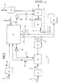
- the numeral 1 in the drawings denotes a line (or plant) for bottling containers of thermoplastic material in continuous cycle.
- the line 1 comprises a moulding unit 3 for making parisons 4 of thermoplastic material from the thermoplastic material in its raw form (for example, pellets 5 of raw, coloured plastic).
- the parison 4 moulding unit 3 is a rotary machine and, preferably, it works the plastic by compression.
- the moulding unit 3 is described in detail in patent document WO2006092651 in the name of the same Applicant as this invention and incorporated herein by reference insofar as concerns the description of the rotary moulding machine.
- the line 1 comprises a thermal conditioning unit 6 for the parisons 4.
- the conditioning unit 6 is configured to receive the parisons from the moulding machine 3 and to heat the parisons 4.
- the conditioning unit 6 is also configured to cool the parisons 4.
- the conditioning unit 6 is configured in such a way that the parisons 4 can be cooled and heated simultaneously or, alternatively, at different times.
- the thermal conditioning unit 6 comprises a heating sub-unit 7 and a cooling sub-unit 8.
- the heating sub-unit 7 comprises, for example, an oven defining a predetermined path for the parisons within a passage where heating elements are arranged (according to a solution of per se known type and not illustrated in detail).
- the cooling sub-unit 8 comprises, for example, a carousel 9.
- the thermal conditioning unit 6 comprises only the oven 7.
- the oven 7 also comprises cooling means which can be operatively activated along at least one stretch of the path followed by the parisons 4 in the oven 7.
- the oven can be switched between a cooling configuration (where the heating means are off or on low heat and the cooling means are on) and a heating configuration (where the heating means are on and the cooling means are off).
- the selfsame oven 7 can also heat and cool different parisons 4 simultaneously.
- the heating means are located in a first portion of the oven 7 and the cooling means in a second portion of the oven 7.
- the first and second portions might be arranged on two levels (the heating means below and the cooling means above, or vice versa) or on consecutive stretches of the oven (first a cooling stretch, followed by a heating stretch).
- the line 1 also comprises a blow-moulding unit 10, comprising a rotary blow-moulding machine in turn comprising a plurality of moulds arranged on a carousel (according to a technique known in the trade, not illustrated).
- a blow-moulding unit 10 comprising a rotary blow-moulding machine in turn comprising a plurality of moulds arranged on a carousel (according to a technique known in the trade, not illustrated).
- the blow-moulding unit 10 is configured to receive the heated parisons 4 from the conditioning unit 6 and to blow-mould them into the moulds in such a way as to make containers 11 (bottles or other PET containers) designed to be filled with liquid or semi-liquid food products.
- the numeral 11 in the drawings denotes the blow-moulded empty containers made available as they feed out of the blow-moulding unit 10.
- the line 1 comprises a filling unit 12 configured to fill the containers 11 with liquid or semi-liquid food products (according to a technique of per se known type, not illustrated in the drawings).
- the line 1 comprises a moulding unit 13 for making plastic caps 14 from plastic material in its raw form (according to a technique of per se known type).
- the line 1 comprises a capping unit 15 configured to apply the caps 14 to the containers 11 filled in the filling unit 12.
- the capping unit 15 is constructed according to a technique of per se known type and is not illustrated in the drawings.
- the line 1 preferably comprises a labelling unit 16 configured to apply labels to the containers 11 according to a technique of per se known type.
- the line 1 preferably comprises a further parison moulding unit 17 comprising a moulding machine (of non-rotary type) which works by injection or by injection and compression).
- the line comprises at least one parison moulding unit (for example, the one labelled 3 in the drawings or the one labelled 17 in the drawings).
- the at least one parison moulding unit may be of any kind, for example, rotary or non-rotary.
- the line comprises (at least) two parison moulding units (for example, the ones labelled 3 and 17 in the drawings).
- the line preferably comprises a rotary parison moulding unit 3 and a non-rotary parison moulding unit 17.
- the filling unit 12 comprises a rotary machine.
- the capping unit 15 comprises a rotary machine.
- the labelling unit 16 comprises a rotary machine.
- the units making up the line 1 are connected to each other in such a way that the products - namely, parisons containers and caps - are transferred from one unit to another substantially in step with each other during the operation of the line.
- the numeral 18 denotes the containers when full, uncapped and unlabelled, the numeral 19, the containers when full, capped but unlabelled, the numeral 20, the containers when full, capped and labelled, the numeral 21, the containers when empty and labelled but uncapped, and the numeral 22, the containers when full and labelled but uncapped.
- the line 1 comprises a warehouse 2.
- the warehouse 2 is configured to contain the parisons 4 and the caps 14.
- the warehouse 2 is preferably configured to also contain the empty, blow-moulded containers 11.
- the warehouse is interconnected with the units of the line 1 through the connections described below.
- the warehouse 2 is connected to the conditioning unit 6 through a conveyor 23 designed to transfer the parisons 4 from the warehouse 2 to the conditioning unit 6 (and more specifically, to the sub-unit 7).
- an orienting device 24 configured to orient and suitably space the parisons 4 through the agency of manipulating means (according to a substantially known technique).
- the orienting device 24 may be built into the warehouse 2 or built into the conditioning unit 6 or it may be inserted in the conveyor 23 (the latter embodiment being the one illustrated in the drawings).
- the warehouse 2 is connected to the conditioning unit 6 through a further conveyor 25 designed to transfer the parisons 4 from the conditioning unit 6 (and more specifically, from the sub-unit 8) to the warehouse 2.
- the warehouse 2 is connected to the cap 14 moulding unit 13 through a conveyor 26 designed to transfer the caps 14 from the cap moulding unit 13 to the warehouse 2.
- the cap 14 moulding unit 13 is connected to the capping unit 15 through a conveyor 27 designed to transfer the caps 14 from the cap moulding unit 13 to the capping unit 15. Inserted in this connection there is an orienting device 24.
- the parison moulding unit 3 is connected directly (for example, by one or more transfer carousels) to the conditioning unit 6.
- the conditioning unit 6 is connected directly (for example, by one or more transfer carousels) to the blow-moulding unit 10.
- the blow-moulding unit 10 is connected (for example by one or more transfer carousels or by other conveyors, preferably provided with positive control of the containers 11) to the filling unit 12.
- the filling unit 12 and the capping unit 15 are defined on a single machine (preferably a rotary machine) or on two distinct machines connected directly to each other (for example by one or more transfer carousels).
- the warehouse 2 is connected to the further parison 4 moulding unit 17 through a conveyor 28 designed to transfer the parisons 4 from the further moulding unit 17 to the warehouse 2.
- the warehouse 2 is connected to the blow-moulding unit 10 through a conveyor 29 designed to transfer the containers 11 from the blow-moulding unit 10 to the warehouse 2.
- the warehouse 2 is connected to the blow-moulding unit 10 through a conveyor 30 designed to transfer the containers 11 from the warehouse 2 to the blow-moulding unit 10. Inserted in this connection there is an orienting device 24.
- the warehouse 2 is connected to the filling unit 12 (or to the labelling unit etichettatrice16) through a conveyor 31 designed to transfer the containers 11 from the warehouse 2 to the filling unit 12 (or to the labelling unit etichettatrice16). Inserted in this connection there is an orienting device 24.
- the warehouse 2 defines inside it a controlled atmosphere environment.
- controlled atmosphere environment is used to mean a pressurized environment (overpressure) or an environment in which there is forced circulation of a predetermined gas.
- the line 1 defines an integrated system where the connections of the units with each other and between the units and the warehouse 2, as described above, are located in a controlled-atmosphere environment.
- connections located in a controlled-atmosphere environment are at least those between the parison moulding unit 3, the thermal conditioning unit 6, the blow-moulding unit 10, the filling unit 12, the cap moulding unit 13, the capping unit 15 and the warehouse 2.
- the controlled-atmosphere environment in the connections of the units of the line 1 with each other and between the selfsame units and the warehouse 2 are made according to two variant embodiments.
- the conveyors 23, 25-31 and the other connections between the units are housed inside ducts (not illustrated) which define sealed chambers in which the controlled atmosphere is created and maintained.
- the line comprises a room (not illustrated) containing the warehouse 2 and all the units making up the line 1.
- the room defines a single sealed chamber in which the controlled atmosphere is created and maintained.
- the line 1 comprises sterilizing (or sanitizing) means operating on the controlled atmosphere environment to make the environment in the chamber aseptic.
- the warehouse 2 is internally pressurized with ionized gas.
- the line 1 comprises an ionizing station (not illustrated), having:
- the ionizing station is coupled to the warehouse 2 in order to ionize the environment inside the warehouse 2.
- the line 1 preferably also comprises a management unit.
- the management unit comprises, for example, an electronic card or a suitably programmed processor or like processing means, and is not illustrated in the drawings.
- the management unit is preferably connected to the warehouse 2 and to all the units making up the line 1 in such a way as to control and/or monitor the line as a whole.
- the management unit is connected to the warehouse 2, to the thermal conditioning unit 6, to the cap moulding unit 13 and to the capping unit 15.
- the management unit is programmed to control the warehouse 2 and these units according to (one or more of) the following operating configurations:
- management unit is configured in such a way that these configurations can be activated alternatively or in combination with each other.
- the management unit is programmed to control the warehouse 2 and the units of the line according to (one or more of) the following operating configurations (the management unit being configured in such a way that these configurations can be activated alternatively or in combination with each other):
- the management unit is programmed to control the warehouse 2 and the units of the line according to the following operating configurations (the management unit being configured in such a way that these configurations can be activated alternatively or in combination with each other):
- the management unit is programmed to control the warehouse 2 and the units of the line according to an operating configuration where the warehouse 2 feeds the labelling unit 16 with the containers 11 and the labelling unit 16 feeds the filling unit 12 with the labelled containers 21 (with reference to Figure 2 ).
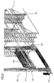
- the warehouse 2 comprises a structure 201 constituting a warehouse frame (for example, a metal lattice frame).
- the structure 201 defines a plurality of housings (or slots) for respective drawers 202 (only partly illustrated).
- the drawers 202 can be accommodated in the housings and are designed to contain objects, such as, for example, parisons, caps or bottles.
- the structure 201 is configured to define a plurality of juxtaposed columns. Each column comprises a plurality of vertically aligned housings.
- the warehouse also comprises a lift 203 having a platform 204 designed to receive and move the drawers 202.
- the lift platform 204 is movable vertically on vertical guide rails 205.
- the lift platform 204 is also movable horizontally.
- the movements of the lift 202 occur through the agency of rolling elements 212.
- the lift 202 is slidably coupled to the structure 201 by wheels 212 (or other rolling elements).
- the platform 204 is coupled to a lift frame 12 or directly to the structure 201 through the agency of wheels 212 (or other rolling elements).
- the combination of the vertical and horizontal movements of the platform allows the platform 204 to reach all the housings in the warehouse, that is, all the drawers housed in the housings in the warehouse.
- the platform 204 is configured to withdraw a drawer 202 from a housing and to insert a drawer into an empty housing.
- the platform 204 is configured to transport two or more drawers 202 at a time.
- the warehouse 2 comprises a drawer 202 washing station (or bay) 206.
- the warehouse 2 preferably also comprises a drawer drying station (not illustrated).
- the warehouse 2 comprises a system of outlet vents 207 (for example connected to fans).
- the outlet vents 207 comprise fans or other means configured to generate an air flow.
- the outlet vents 207 are located in a zone of the warehouse 2 which is therefore a high-pressure zone of the warehouse 2.
- the outlet vents 207 are oriented in a predetermined direction, towards a low-pressure zone of the warehouse 2.
- the high- and low-pressure zones of the warehouse are located at opposite ends of the warehouse 2, so as to create a (laminar) flow of air through the entire space inside the warehouse 2. This flow is represented by the arrows 208 in Figure 10 .
- the warehouse 2 also comprises a system of inlet vents 209 (for example connected to fans) located in the low-pressure zone of the warehouse.
- the pressure in the low-pressure zone is lower than that in the high-pressure zone but higher than the pressure of the environment outside the warehouse (that is, outside the bottling line; typically, this environment is a room in which the line is installed).
- the drawers 202 are provided with holes to allow an air flow to pass through them.
- the structure 201 is internally provided with a plurality of holes or openings oriented in the same direction as the outlet vents 207 are oriented, so as to allow the air flow to move easily in the space inside the warehouse 2.
- the drawer housings have holes in them (for example, they are defined by grids).
- the system of outlet vents 207 and inlet vents 209 are connected to ducts 210 to form a recirculating air flow inside the warehouse 2 (in a closed circuit).
- the warehouse comprises a plurality of filters (not illustrated) coupled to the outlet vents (downstream of the corresponding pressure fans) to filter the air delivered into the warehouse 2.
- the warehouse has the shape of a parallelepiped and has a rectangular base, with two long sides and two short sides.
- the warehouse accordingly has a lateral wall with two large faces and two small faces.
- the high- and low-pressure zones are located at opposite faces of the lateral wall of the warehouse, This allows the air to flow through the whole of the warehouse.
- the high- and low-pressure zones are located on the small faces of the lateral wall. This allows minimizing the number of outlets/inlets 207, 209, thus simplifying warehouse construction.
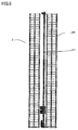
- the warehouse 2 includes an empty passage which cuts the small lateral faces and separates the warehouse into two parts along a dividing plane parallel to the large lateral faces.
- the lift 203 comprises a frame having two vertical uprights (whose length is equal to the height of the warehouse) which define the vertical guide rails 205.
- the uprights are slidably coupled to opposite ends of the carriage 204.
- the lift frame has the shape of the perimeter of a rectangle since the vertical uprights are closed by crossbars at the ends of them.
- the lift (that is, the lift frame) is movable horizontally along a (horizontal,) direction parallel to the large faces.
- the frame runs on horizontal guides, that is on horizontal rails 211, extending along the dividing plane.
- the carriage 204 and the drawers 202 are positioned perpendicularly to the planes defined by the small lateral faces of the warehouse (and parallel to the large lateral faces).
- the carriage 204 and the drawers 202 are positioned parallel to the planes defined by the small lateral faces of the warehouse.
- the warehouse 2 has a plurality of empty passages (vertical aisles) which cut the large lateral faces and separate the warehouse into a plurality of parts along dividing planes parallel to the small lateral faces.
- vertical aisles vertical aisles
- predetermined levels that is, at one or more predetermined heights from the warehouse floor
- These horizontal slideways for the carriage 204 define one or more horizontal aisles along which the carriage 204 can move.
- the at least one horizontal aisle for the movement of the carriage 204 is preferably located at the highest level of the warehouse (near the warehouse ceiling) or at the lowest level (near the warehouse floor).
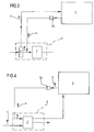
- Figure 6 shows a duct 101.
- the duct 101 connects the further parison moulding unit 17 to the warehouse 2.
- the line comprises outlet vents (not illustrated) located in zones (limited stretches) of the ducts which enclose the conveyors, that is, the connections between the different units making up the line.
- the line defines a sealed space within the line itself, which is kept at a higher pressure than in the environment outside the line (that is, the environment in the room where the line is installed).
- This solution allows saving of energy and is a better guarantee against contamination than a solution where the entire room in which the line is installed is pressurized.
- the line connecting ducts are kept at a predetermined internal pressure and the pressure is distributed in a predetermined manner to define zones where the pressure is relatively high and zones where the pressure is relatively low thanks to the location of outlet vents at predetermined positions (zones) of the ducts of the line.
- This invention also provides a continuous cycle method for bottling containers of thermoplastic material.
- the method comprises the following steps:
- the method of the invention comprises a step of pressurizing (or for the forced circulation of a predetermined gas or for the sterilisation of) the warehouse 2 in order to define therein a controlled atmosphere environment which is preferably (but not necessarily) sterile.
- the method comprises transferring the objects (parisons 4, containers 11 and caps 14) circulating in the line 1 in a controlled atmosphere environment within an integrated system defined by the warehouse 2 and by the units making up the line 1.
- the line 1 there is also a step of controlling the line 1, with the possibility of managing the warehouse 2 and the units (generally speaking, the units concerned are those labelled 3, 6, 10, 12, 13, 15 and 17) according to (one or more of) the following operating configurations (alternatively or in combination):
- the step of controlling the line 1 comprises managing the warehouse 2 and the units according to (one or more of) the following operating configurations (alternatively or in combination):
- the method also comprises a step of creating and maintaining the controlled atmosphere environment (preferably, but not necessarily, aseptic) during the operation of the line.
Landscapes
- Engineering & Computer Science (AREA)
- Mechanical Engineering (AREA)
- Manufacturing & Machinery (AREA)
- Physics & Mathematics (AREA)
- Thermal Sciences (AREA)
- Blow-Moulding Or Thermoforming Of Plastics Or The Like (AREA)
- Warehouses Or Storage Devices (AREA)
- Filling Of Jars Or Cans And Processes For Cleaning And Sealing Jars (AREA)
Claims (15)
- Ligne d'embouteillage à cycle continu (1) pour récipients en matière thermoplastique, comprenant :- une unité de moulage (3) pour fabriquer des paraisons (4) constituées de matière thermoplastique à partir de matière thermoplastique à l'état brut (5) ;- une unité de conditionnement thermique (6) de paraisons (4) configurée pour recevoir les paraisons (4) de la machine à mouler (3) et pour chauffer et refroidir les paraisons (4) ;- une unité de moulage par soufflage (10) configurée pour recevoir les paraisons chauffées (4) de l'unité de conditionnement (6) et pour les mouler par soufflage de manière à réaliser des récipients (11) conçus pour être remplis ;- une unité de remplissage (12) configurée pour recevoir les récipients (11) de l'unité de moulage par soufflage (10) et pour les remplir de produits alimentaires liquides ou semi-liquides ;- une unité d'encapsulage (15) configurée pour recevoir des bouchons (14) en matière thermoplastique et pour appliquer fermement les bouchons (14) aux récipients pleins (18) respectifs ;- un système de stockage (2), configuré pour contenir les paraisons (4) et relié à l'unité de conditionnement thermique (6) par un ou plusieurs convoyeurs (23, 25), pour recevoir les paraisons (4) à stocker et pour alimenter la même unité de conditionnement thermique (6) avec les paraisons (4) stockées antérieurement, dans laquelle le système de stockage (2) définit en son sein un environnement à atmosphère contrôlée et en ce que la ligne d'embouteillage (1) définit un système intégré où les raccordements entre l'unité de moulage (3) de paraisons (4), l'unité de conditionnement thermique (6), l'unité de moulage par soufflage (10), l'unité de remplissage (12), l'unité d'encapsulage (15) et le système de stockage (2) définissent en leur sein un environnement à atmosphère contrôlée, caractérisée en ce que lesdits raccordements sont enfermés à l'intérieur de conduits respectifs délimitant des espaces fermés à l'intérieur desquels l'atmosphère contrôlée peut être créée et maintenue.
- Ligne d'embouteillage selon la revendication 1, comprenant :une unité de moulage (13) pour fabriquer des bouchons (14) en matière plastique à partir de matière plastique à l'état brut (5), l'unité d'encapsulage (15) étant configurée pour recevoir les bouchons (14) de l'unité de moulage (13) de bouchons (14), dans laquelle le système de stockage (2) est configuré pour aussi contenir des bouchons (14) et est relié par un ouplusieurs convoyeurs (26, 31) à l'unité de moulage (13) de bouchons pour recevoir des bouchons (14) à stocker et à l'unité d'encapsulage (15) pour alimenter cette dernière avec des bouchons (14) stockés antérieurement,et dans laquelle les raccordements entre l'unité de moulage (13) de bouchons (14), l'unité d'encapsulage (15) et le système de stockage (2) définissent en leur sein un environnement à atmosphère contrôlée ;une unité de gestion reliée au système de stockage (2),à l'unité de conditionnement thermique (6), à l'unité de moulage (13) de bouchons (14) et à l'unité d'encapsulage (15) et programmée pour commander le système de stockage (2) et les unités (6, 13, 15) selon les configurations de fonctionnement suivantes :- l'unité de conditionnement thermique (6) se trouve dans le mode de chauffage des paraisons (4) et alimente l'unité de moulage par soufflage (10) ;- l'unité de conditionnement thermique (6) se trouve dans le mode de refroidissement des paraisons (4) et alimente le système de stockage (2) ;- l'unité de moulage (13) de bouchons (14) alimente l'unité d'encapsulage (15) ;- l'unité de moulage (13) de bouchons (14) alimente le système de stockage (2), dans laquelle l'unité de conditionnement thermique (6) comprend une sous-unité de chauffage (7) ayant l'entrée reliée à l'unité de moulage (3) de paraisons (4) et au système de stockage (2) et la sortie reliée à l'unité de moulage par soufflage (10), ainsi qu'une sous-unité de refroidissement (8) ayant l'entrée reliée à l'unité de moulage (3) de paraisons (4) et la sortie reliée au système de stockage (2), et dans laquelle l'unité de gestion est programmée pour commander le système de stockage (2) et les unités de la ligne (1) selon les configurations de fonctionnement suivantes :- la sous-unité de refroidissement (8) est fermée pendant que la sous-unité de chauffage (7) fonctionne et reçoit les paraisons (4) de l'unité de moulage (3) de paraisons (4) et les alimente à l'unité de moulage par soufflage (10) ;- la sous-unité de refroidissement (8) fonctionne et reçoit les paraisons (4) de l'unité de moulage (3) de paraisons (4) et les alimente au système de stockage (2) pendant que la sous-unité de chauffage (7) fonctionne et reçoit les paraisons (4) du système de stockage (2) et les alimente à l'unité de moulage par soufflage (10) ;- l'unité de moulage (13) de bouchons (14) alimente le système de stockage (2) pendant que le système de stockage (2) alimente l'unité d'encapsulage (15).
- Ligne d'embouteillage selon l'une quelconque des revendications précédentes, dans laquelle lesdits conduits enfermant les raccordements entre une unité et une autre de la ligne sont maintenus à une pression étant supérieure à la pression à l'extérieur de la ligne.
- Ligne d'embouteillage selon l'une quelconque des revendications précédentes, comprenant des moyens de stérilisation opérant dans l'environnement à atmosphère contrôlée afin d'en faire un environnement aseptique.
- Ligne d'embouteillage selon l'une quelconque des revendications précédentes, dans laquelle le système de stockage (2) est mis sous pression à l'intérieur avec du gaz ionisé.
- Ligne d'embouteillage selon l'une quelconque des revendications précédentes, dans laquelle le système intégré, comprenant l'unité de moulage (3) de paraisons (4), l'unité de conditionnement thermique (6), l'unité de moulage par soufflage (10), l'unité de remplissage (12), l'unité d'encapsulage (15) et le système de stockage (2), définit en son sein une pluralité d'espaces mis sous pression et interconnectés correspondants pour permettre aux paraisons (4) de se déplacer à l'intérieur de la ligne tout en restant en permanence dans un environnement à atmosphère contrôlée.
- Ligne d'embouteillage selon la revendication 6, comprenant une pluralité de tuyaux d'aération qui fonctionnent sur des espaces correspondants faisant partie de la pluralité d'espaces pour les maintenir à des pressions de référence respectives.
- Ligne d'embouteillage selon la revendication 1, dans laquelle lesdits espaces sont mis sous pression indépendamment les uns des autres.
- Ligne d'embouteillage selon les revendications 1 ou 8, dans laquelle les conduits qui enferment les raccordements à l'entrepôt disposent d'une pression intérieure étant inférieure à celle de l'entrepôt et les conduits qui enferment les raccordements aux unités disposent d'une pression intérieure étant inférieure à celle des unités qu'ils relient.
- Procédé à cycle continu pour embouteiller des récipients en matière thermoplastique, comprenant les étapes suivantes :- mouler des paraisons (4) à partir de matière thermoplastique à l'état brut (5) ;- conditionner thermiquement les paraisons (4) par chauffage et refroidissement de celles-ci ;- mouler par soufflage les paraisons chauffées (4) afin de fabriquer des récipients (11) en matière thermoplastique ;- remplir les récipients (18) avec des produits liquides ou semi-liquides ;- encapsuler les récipients pleins (19) ;- prédisposer un système de stockage (2) configuré pour contenir les paraisons (4), dans lequel le système de stockage (2) définit en son sein un environnement à atmosphère contrôlée,et en ce que les unités (3, 6, 10, 12, 15, 16, 17) et le système de stockage (2) constituent une ligne d'embouteillage (1) qui définit un système intégré dans lequel les mouvements destinés à transférer les paraisons (4) et les récipients (11, 18, 19, 20, 21, 22) entre lesdites unités (3, 6, 10, 12, 15, 16, 17) et entre le système de stockage (2) et au moins l'unité de conditionnement thermique (6) sont effectués dans un environnement à atmosphère contrôlée, caractérisé en ce que lesdits raccordements entre lesdites unités sont enfermés à l'intérieur de conduits respectifs délimitant des espaces fermés à l'intérieur desquels l'atmosphère contrôlée peut être créée et maintenue.
- Procédé selon la revendication 10, comprenant une étape de moulage de bouchons (14) à partir de matière plastique à l'état brut (5), dans lequel le système de stockage (2) est configuré pour aussi contenir des bouchons (14) et dans lequel les mouvements par lesquels les bouchons (14) sont transférés à l'intérieur du système intégré sont effectués dans un environnement à atmosphère contrôlé à l'intérieur de la ligne, et comprenant une étape de commande de la ligne d'embouteillage (1), avec la possibilité de gérer le système de stockage (2) et les unités (3, 6, 10, 12, 13, 15, 16, 17) selon les configurations de fonctionnement suivantes :- l'unité de conditionnement thermique (6) se trouve dans le mode de chauffage des paraisons (4) et alimente l'unité de moulage par soufflage (10) ;- l'unité de conditionnement thermique (6) se trouve dans le mode de refroidissement des paraisons (4) et alimente le système de stockage (2) ;- l'unité de moulage (13) de bouchons (14) alimente l'unité d'encapsulage (15) ;- l'unité de moulage (13) de bouchons (14) alimente le système de stockage (2),dans lequel l'étape de commande comprend la gestion du système de stockage (2) et des unités (3, 6, 10, 12, 13, 15, 16, 17) selon les configurations de fonctionnement suivantes :- alimenter l'unité de moulage par soufflage (10) de paraisons (4) sortant de la sous-unité de chauffage (7) de l'unité de conditionnement thermique (6) ;- alimenter la sous-unité de chauffage (7) de l'unité de conditionnement thermique (6) de paraisons (4) sortant du système de stockage (2) et transférer simultanément les paraisons (4) de l'unité de moulage (3) de paraisons (4) au système de stockage (2) ;- transférer les bouchons (14) sortant de l'unité de moulage (13) de bouchons au système de stockage (2) pendant que le système de stockage (2) alimente l'unité d'encapsulage (15).
- Procédé d'embouteillage selon l'une quelconque des revendications de 10 à 11, dans lequel l'environnement à atmosphère contrôlée est maintenu dans un état aseptique lors du fonctionnement de la ligne (1).
- Procédé d'embouteillage selon l'une quelconque des revendications de 10 à 12, dans lequel le système intégré, comprenant l'unité de moulage (3) de paraisons (4), l'unité de conditionnement thermique (6), l'unité de moulage par soufflage (10), l'unité de remplissage (12), l'unité d'encapsulage (15) et le système de stockage (2), définit en son sein une pluralité d'espaces mis sous pression et interconnectés correspondants de sorte que les paraisons (4) sont déplacées à l'intérieur de la ligne le long de trajectoires prédéfinies tout en restant en permanence dans un environnement à atmosphère contrôlée à l'intérieur de la ligne.
- Procédé d'embouteillage selon la revendication 13, comprenant une étape de mise sous pression des espaces correspondants faisant partie d'une pluralité d'espaces pour les maintenir à des pressions de référence respectives, dans lequel lesdits conduits enfermant les raccordements entre une unité et une autre de la ligne sont maintenus à une pression étant supérieure à la pression à l'extérieur de la ligne.
- Procédé d'embouteillage selon les revendications 10 ou 14, dans lequel les conduits qui enferment les raccordements à l'entrepôt disposent d'une pression intérieure étant inférieure à celle de l'entrepôt et les conduits qui enferment les raccordements aux unités disposent d'une pression intérieure étant inférieure à celles des unités qu'ils relient.
Applications Claiming Priority (2)
| Application Number | Priority Date | Filing Date | Title |
|---|---|---|---|
| IT000691A ITBO20110691A1 (it) | 2011-12-02 | 2011-12-02 | Linea e procedimento di imbottigliamento in ciclo continuo di contenitori in materiale termoplastico. |
| PCT/IB2012/056922 WO2013080189A1 (fr) | 2011-12-02 | 2012-12-03 | Chaîne et procédé d'embouteillage |
Publications (2)
| Publication Number | Publication Date |
|---|---|
| EP2785507A1 EP2785507A1 (fr) | 2014-10-08 |
| EP2785507B1 true EP2785507B1 (fr) | 2016-06-15 |
Family
ID=45571593
Family Applications (1)
| Application Number | Title | Priority Date | Filing Date |
|---|---|---|---|
| EP12813511.8A Active EP2785507B1 (fr) | 2011-12-02 | 2012-12-03 | Ligne d'embouteillage et procédé |
Country Status (8)
| Country | Link |
|---|---|
| US (5) | US10773941B2 (fr) |
| EP (1) | EP2785507B1 (fr) |
| JP (2) | JP6148678B2 (fr) |
| CN (1) | CN104080589B (fr) |
| ES (6) | ES2588586T3 (fr) |
| IN (1) | IN2014CN04068A (fr) |
| IT (1) | ITBO20110691A1 (fr) |
| WO (1) | WO2013080189A1 (fr) |
Cited By (1)
| Publication number | Priority date | Publication date | Assignee | Title |
|---|---|---|---|---|
| EP3902662B1 (fr) * | 2018-12-28 | 2023-02-22 | Synerlink | Ligne de preparation et de remplissage de bouteilles |
Families Citing this family (24)
| Publication number | Priority date | Publication date | Assignee | Title |
|---|---|---|---|---|
| ITBO20110691A1 (it) | 2011-12-02 | 2013-06-03 | Ativa | Linea e procedimento di imbottigliamento in ciclo continuo di contenitori in materiale termoplastico. |
| US11027862B2 (en) * | 2014-06-23 | 2021-06-08 | Woodstock Sterile Solutions, Inc. | Cold blow-fill-seal packaging system and process |
| RU2685500C2 (ru) * | 2014-09-22 | 2019-04-18 | Сакми Кооператива Мекканичи Имола Сочиета' Кооператива | Линия для производства индивидуальных изделий последовательно в непрерывном цикле |
| ITBO20150203A1 (it) * | 2015-04-21 | 2016-10-21 | Sacmi | Apparato e metodo di ispezione ottica di preforme. |
| EP3144234A1 (fr) * | 2015-09-21 | 2017-03-22 | Sidel Participations | Appareil de production de bouteilles en plastique |
| MY202296A (en) * | 2016-05-31 | 2024-04-23 | Dainippon Printing Co Ltd | Cap sterilizer, content filling system, and cap sterilization method |
| DE102017112455A1 (de) | 2017-06-06 | 2018-12-06 | Krones Ag | Vorrichtung und Verfahren zum Behandeln und insbesondere Transportieren von Kunststoffvorformlingen |
| IT201700089679A1 (it) * | 2017-08-03 | 2019-02-03 | Gea Procomac Spa | Apparato per produrre recipienti sterili, impianto di imbottigliamento comprendente tale apparato e metodo per produrre un recipiente sterile |
| MX2020006044A (es) | 2017-12-18 | 2020-08-17 | Sipa Progettazione Automaz | Sistema y proceso de produccion de contenedores de material termoplastico. |
| EP3514085B1 (fr) * | 2018-01-18 | 2023-11-08 | M. Tanner AG | Unité de transport et d'alimentation pour préformés |
| DE102019108683A1 (de) * | 2019-04-03 | 2020-10-08 | Krones Ag | Verfahren und Vorrichtung zum Verschließen von Behältern mit Behälterverschlüssen |
| US10842894B1 (en) * | 2019-07-30 | 2020-11-24 | Steribin, LLC | Systems and methods for treating a contaminated container |
| AU2021200246A1 (en) | 2020-01-31 | 2021-08-19 | Howmedica Osteonics Corp. | Injection molding feedstock delivery system |
| IT202000009685A1 (it) * | 2020-05-04 | 2021-11-04 | Smi Spa | Macchina per il confezionamento di liquidi o prodotti semisolidi in contenitori |
| CN112374011B (zh) * | 2020-11-26 | 2022-11-15 | 湖南祥柏生态环保科技有限公司 | 病死动物尸体储存冷库 |
| CN112429512B (zh) * | 2020-11-26 | 2022-12-02 | 湖南祥柏生态环保科技有限公司 | 病死动物尸体储存冷库的堆垛设备 |
| CN112723289B (zh) * | 2020-12-30 | 2024-08-09 | 天津市虎豹调味品酿造有限公司 | 一种油制颗粒类酱料灌装装置 |
| US11679171B2 (en) | 2021-06-08 | 2023-06-20 | Steribin, LLC | Apparatus and method for disinfecting substances as they pass through a pipe |
| DE102021134503A1 (de) | 2021-12-23 | 2023-06-29 | Krones Aktiengesellschaft | Vorrichtung und Verfahren zum Behandeln und insbesondere Sterilisieren von Behältnissen |
| CN114603824B (zh) * | 2022-03-01 | 2024-12-20 | 湖南千山制药机械股份有限公司 | 直线式注吹灌封一体的塑料瓶包装设备 |
| CN114603823A (zh) * | 2022-03-01 | 2022-06-10 | 湖南千山制药机械股份有限公司 | 直线式注吹灌封一体的塑料瓶包装设备 |
| CH719525A1 (de) * | 2022-03-23 | 2023-09-29 | Alpla Werke Alwin Lehner Gmbh & Co Kg | Extrusionsblasformmaschine. |
| DE102023119034A1 (de) * | 2023-07-19 | 2025-01-23 | Krones Aktiengesellschaft | Behälterbehandlungsanlage zum Herstellen und Behandeln von Vorformlingen |
| FR3166570A1 (fr) * | 2024-09-26 | 2026-03-27 | Sidel Participations | Installation de fabrication de corps creux comportant une cavite de collection de corps creux ejectes |
Family Cites Families (84)
| Publication number | Priority date | Publication date | Assignee | Title |
|---|---|---|---|---|
| BE627821A (fr) | 1962-02-01 | |||
| DE2615815A1 (de) * | 1976-04-10 | 1977-10-27 | Boehringer Mannheim Gmbh | Maschine zum kontinuierlichen herstellen und verpacken von gefriertrocknungsgut |
| JPS5836810A (ja) | 1981-08-28 | 1983-03-03 | Toshiba Corp | 紙葉類群の搬送装置 |
| NL8202209A (nl) * | 1982-06-01 | 1984-01-02 | Unilever Nv | Werkwijze en inrichting voor het aseptisch verpakken van produkten zoals voedingsmiddelen en farmaceutische produkten. |
| JPS6048802A (ja) | 1983-08-24 | 1985-03-16 | Yoshizo Ada | 立体収納庫の棚体搬送装置 |
| US5059079A (en) | 1989-05-16 | 1991-10-22 | Proconics International, Inc. | Particle-free storage for articles |
| JP3462534B2 (ja) | 1992-08-28 | 2003-11-05 | テキサス インスツルメンツ インコーポレイテツド | プログラマブル論理回路および方法 |
| US5409545A (en) | 1993-03-04 | 1995-04-25 | Environmental Sampling Supply, Inc. | Apparatus and method for cleaning containers |
| JPH08164925A (ja) * | 1994-12-12 | 1996-06-25 | Coca Cola Co:The | 飲料包装装置 |
| US5702734A (en) * | 1994-12-19 | 1997-12-30 | Electra Form, Inc. | Take-out and cooling apparatus |
| FR2732002B1 (fr) * | 1995-03-23 | 1997-06-06 | Sidel Sa | Installation d'embouteillage en ligne |
| JPH0939110A (ja) * | 1995-07-31 | 1997-02-10 | Mitsubishi Heavy Ind Ltd | 樹脂製容器の製造設備 |
| US5953234A (en) | 1996-03-12 | 1999-09-14 | Woodson Incorporated | Automated storage facility including a storage and retrieval system and a floor inventory management system |
| JPH10167226A (ja) * | 1996-12-10 | 1998-06-23 | Daiwa Can Co Ltd | プラスチックボトルの無菌充填設備 |
| FR2765566B1 (fr) * | 1997-07-03 | 1999-09-17 | Sidel Sa | Installation de conditionnement d'un produit dans des recipients fermes par un bouchon et dispositif de stockage dynamique de bouchons utilisable dans celle-ci |
| DE19731796A1 (de) * | 1997-07-24 | 1999-01-28 | Kronseder Maschf Krones | Verfahren und Vorrichtung zum hochreinen Abfüllen von Getränken in Flaschen |
| DE19806520A1 (de) * | 1998-02-17 | 1999-08-19 | Ruediger Haaga Gmbh | Verfahren zum Sterilisieren, Befüllen und Verschließen von Behältern |
| JP4216467B2 (ja) * | 1998-03-13 | 2009-01-28 | ベクトン・ディキンソン・アンド・カンパニー | 医療装置の組立ておよび包装方法 |
| AU4032999A (en) | 1998-04-23 | 1999-11-16 | Certus Maschinenbau Gmbh | Device for processing bottles |
| IT1303365B1 (it) | 1998-10-13 | 2000-11-06 | Adriano Sartor | Dispositivo di preparazione di preforme per impianti di fabbricazionedi bottiglie e contenitori o prodotti di vario genere. |
| US6536188B1 (en) * | 1999-02-02 | 2003-03-25 | Steuben Foods, Inc. | Method and apparatus for aseptic packaging |
| US7707807B2 (en) | 2004-03-08 | 2010-05-04 | Medical Instill Technologies, Inc. | Apparatus for molding and assembling containers with stoppers and filling same |
| US7669390B2 (en) * | 2004-03-08 | 2010-03-02 | Medical Instill Technologies, Inc. | Method for molding and assembling containers with stoppers and filling same |
| DE10013092C2 (de) | 2000-03-17 | 2002-01-24 | Haenel & Co Altstaetten | Lagerregal |
| DE10050660B4 (de) * | 2000-10-13 | 2018-06-28 | Robert Bosch Gmbh | Verfahren und Vorrichtung zur Herstellung von mit sterilen Erzeugnissen gefüllten und verschlossenen Behältern |
| JP2003081441A (ja) | 2001-09-14 | 2003-03-19 | Daifuku Co Ltd | 取り扱い設備 |
| US7016753B2 (en) | 2001-10-30 | 2006-03-21 | Semiconductor Energy Laboratory Co., Ltd. | Management system for production line and management method for production line |
| US20080017045A1 (en) * | 2001-11-26 | 2008-01-24 | Vin Valet, Inc. | Apparatus and method for preserving, protecting, or enhancing items including solids or liquids |
| JP2006512258A (ja) * | 2002-12-27 | 2006-04-13 | アドバンスド プラスティックス テクノロジーズ リミテッド | フレキシブルポーチの製造及び充填のための装置及び方法 |
| DE10313577B4 (de) * | 2003-03-26 | 2009-01-08 | Witron Logistik + Informatik Gmbh | Automatisiertes System und Verfahren zum Lagern und Kommissionieren von Artikeln |
| JPWO2004106009A1 (ja) | 2003-06-02 | 2006-07-20 | 松下電器産業株式会社 | 物品取扱いシステムおよび物品取扱いサーバ |
| JP4356066B2 (ja) * | 2003-10-17 | 2009-11-04 | 東洋製罐株式会社 | 圧縮成形および延伸ブロー成形からなる容器の製造方法ならびに製造装置 |
| WO2005070644A1 (fr) | 2004-01-09 | 2005-08-04 | The Coca-Cola Company | Procede et appareil de moulage par compression-condensation utiles pour produire des preformes de contenant |
| JP2005280880A (ja) | 2004-03-29 | 2005-10-13 | Takuma Co Ltd | 再資源化物の保管設備 |
| US20050230639A1 (en) * | 2004-04-14 | 2005-10-20 | Kash 'n Gold, Ltd. | Knife and kitchen tool sterilizer and holder |
| DE102004026883B4 (de) * | 2004-05-27 | 2014-12-24 | Inova Pharma Systems Gmbh | Anordnung zum sterilen Abfüllen |
| TW200619113A (en) | 2004-12-02 | 2006-06-16 | Murata Machinery Ltd | Automatic warehouse |
| ITMO20050048A1 (it) | 2005-03-01 | 2006-09-02 | Sacmi | Apparati e metodi. |
| DE102005012507A1 (de) * | 2005-03-16 | 2006-09-21 | Krones Ag | Verfahren und Vorrichtung betrefffend das Sterilabfüllen von Flüssigkeiten |
| JP2007106438A (ja) | 2005-10-13 | 2007-04-26 | Toyo Seikan Kaisha Ltd | 包装体の殺菌方法及び殺菌装置 |
| DE102006013800C5 (de) * | 2006-03-24 | 2010-04-15 | Khs Ag | Transportsystem für Flaschen oder dergleichen Behälter sowie Anlage zum Behandeln von Flaschen oder dergleichen Behälter |
| DE102006013843A1 (de) * | 2006-03-25 | 2007-09-27 | Khs Ag | Blasmaschine sowie Verfahren zum Herstellen von Flaschen oder dergleichen Hohlkörper |
| DE102006026279B4 (de) * | 2006-06-02 | 2016-02-25 | Khs Gmbh | Verfahren sowie Vorrichtung zum Herstellen von Verpackungseinheiten oder Gebinden |
| US7763546B2 (en) * | 2006-08-02 | 2010-07-27 | Qualcomm Mems Technologies, Inc. | Methods for reducing surface charges during the manufacture of microelectromechanical systems devices |
| DE102006053193A1 (de) * | 2006-11-09 | 2008-05-15 | Krones Ag | Vorrichtung und Verfahren zur Herstellung von Kunststoffbehältern |
| BRPI0807856A2 (pt) | 2007-01-25 | 2014-06-17 | Netstal Ag Maschf Giesserei | Dispositivo de resfriamento posterior e processo para o resfriamento posterior de pré-formas. |
| FR2915418B1 (fr) | 2007-04-25 | 2012-11-16 | Sidel Participations | Procede de chauffe d'ebauches pour la fabrication de recipients |
| ITBO20070386A1 (it) | 2007-05-31 | 2008-12-01 | Sacmi | Unita' per la presa di manufatti ceramici od assimilabili. |
| CN101835840A (zh) * | 2007-10-23 | 2010-09-15 | 陶氏环球技术公司 | 改良的拉伸吹塑单亚乙烯基芳族聚合物 |
| US20090186571A1 (en) * | 2008-01-22 | 2009-07-23 | Asm America, Inc. | Air ventilation system |
| WO2009092166A1 (fr) * | 2008-01-23 | 2009-07-30 | Kl Products Inc. | Désempiler et rempiler des récipients à l'aide d'un robot lors d'opérations d'incubation de volaille |
| ITRE20080025A1 (it) | 2008-02-22 | 2009-08-23 | Opem S P A | Impianto per la fabbricazione di capsule monodose per la preparazione di bevande |
| EP2546176B1 (fr) * | 2008-04-18 | 2016-01-20 | SACMI Cooperativa Meccanici Imola Società Cooperativa | Procédé et appareil de moulage par compression et soufflage |
| DE102008021527B4 (de) * | 2008-04-30 | 2023-06-29 | Krones Aktiengesellschaft | Anlage und Verfahren zur Herstellung von Behältern |
| CN103588154B (zh) * | 2008-05-20 | 2016-07-27 | 大日本印刷株式会社 | 饮料填充装置 |
| DE102008030267B3 (de) * | 2008-06-19 | 2010-01-28 | Arzneimittel Gmbh Apotheker Vetter & Co. Ravensburg | Verfahren zum Befüllen von Doppelkammersystemen in vorsterilisierbaren Trägersystemen und vorsterilisierbares Trägersystem |
| IT1396851B1 (it) * | 2008-07-29 | 2012-12-20 | Sacmi | Impianto per il soffiaggio di contenitori di plastica, in particolare bottiglie |
| US8359877B2 (en) * | 2008-08-15 | 2013-01-29 | Deka Products Limited Partnership | Water vending apparatus |
| DE102008038143A1 (de) * | 2008-08-18 | 2010-02-25 | Krones Ag | Vorrichtung zum Sterilisieren von Kunststoffvorformlingen |
| CN102196889B (zh) * | 2008-08-28 | 2014-10-15 | 东洋制罐株式会社 | 用于压缩成形预成型体的金属模具、预成型体、使用预成型体无菌填充饮料和食品的系统以及制造吹塑成形的容器的制造方法 |
| DE102008048812A1 (de) * | 2008-09-24 | 2010-04-01 | Khs Ag | Verfahren und Vorrichtung zur kombinierten Herstellung und Abfüllung von Behältern aus Kunststoff |
| DE102008057403A1 (de) * | 2008-11-14 | 2010-05-20 | Krones Ag | Vorrichtung und Verfahren zum Herstellen von Kunststoffbehältnissen |
| US20100133729A1 (en) * | 2008-12-01 | 2010-06-03 | Graham Packaging Company, L.P. | Method and Apparatus for Manufacturing Wide Mouth Containers |
| DE102008061492A1 (de) * | 2008-12-10 | 2010-06-17 | Krones Ag | Verfahren und Vorrichtung zur ökonomischen Herstellung von Kunststoffbehältern |
| JP5336949B2 (ja) * | 2009-06-30 | 2013-11-06 | サントリーホールディングス株式会社 | 樹脂製容器の帯電除去方法、樹脂製容器の殺菌充填方法、樹脂製容器の充填キャッピング方法、樹脂製容器の帯電除去装置および樹脂製容器の殺菌充填システム |
| DE102009040363A1 (de) * | 2009-09-07 | 2011-03-10 | Krones Ag | Vorrichtung und Verfahren zum Herstellen von Kunststoffflaschen |
| IT1395922B1 (it) * | 2009-09-24 | 2012-11-02 | Iwt Srl | Sistema automatizzato per il ribaltamento, traslazione , riempimento in linea di dispositivi di contenimento di animali da laboratorio in aree di lavaggio |
| IT1396834B1 (it) * | 2009-11-18 | 2012-12-14 | Sacmi Labelling S P A Ora Sacmi Verona S P A | Procedimento di produzione di etichette a manicotto e dispositivo per la loro produzione. |
| IT1396699B1 (it) | 2009-11-19 | 2012-12-14 | Unitec Spa | Impianto perfezionato per la pulizia di contenitori per prodotti vegetali. |
| US9037286B2 (en) | 2010-03-12 | 2015-05-19 | Symbotic Llc | Each pick |
| DE102010022128B4 (de) | 2010-05-20 | 2012-03-15 | Krones Aktiengesellschaft | Vorrichtung zum Umformen von Kunststoffvorformlingen mit Sterilraum |
| CN102917956B (zh) * | 2010-05-25 | 2016-03-23 | 大塚制药株式会社 | 无菌充填系统 |
| DE102010021446A1 (de) * | 2010-05-25 | 2011-12-01 | Krones Ag | Verfahren und Vorrichtung zur Temperierung von Vorformlingen |
| DE102010029644A1 (de) | 2010-06-02 | 2011-12-08 | Krones Ag | Vorrichtung und Verfahren zum Herstellen von Kunststoffbehältern |
| IT1400833B1 (it) * | 2010-06-25 | 2013-07-02 | Sipa Progettazione Automaz | Impianto di produzione di contenitori di plastica |
| JP5440871B2 (ja) * | 2010-08-20 | 2014-03-12 | 株式会社ダイフク | 容器保管設備 |
| DE102010042165A1 (de) * | 2010-10-07 | 2012-04-12 | Krones Aktiengesellschaft | Verfahren zum Behandeln wenigstens eines Behälters in einer Behälterbehandlungsanlage |
| DE102010049385A1 (de) | 2010-10-26 | 2012-04-26 | Krones Aktiengesellschaft | Blasmaschine in Modulbauweise |
| DE102010056450A1 (de) | 2010-12-23 | 2012-06-28 | Khs Corpoplast Gmbh | Verfahren und Vorrichtung zur Blasformung von sterilen Behältern |
| US8996160B2 (en) | 2010-12-27 | 2015-03-31 | Itoh Denki Co., Ltd. | Article storage device and conveyor used therein |
| US10696434B2 (en) | 2011-01-31 | 2020-06-30 | Khs Gmbh | Method and device for producing containers which are filled with a liquid filling substance |
| DE102011101256A1 (de) * | 2011-05-11 | 2012-11-15 | Krones Aktiengesellschaft | Aseptische Blasformmaschine mit steriler Luftabführung |
| ITBO20110691A1 (it) | 2011-12-02 | 2013-06-03 | Ativa | Linea e procedimento di imbottigliamento in ciclo continuo di contenitori in materiale termoplastico. |
| WO2013113384A1 (fr) | 2012-02-01 | 2013-08-08 | Conteno | Installation d'embouteillage transportable montée dans un conteneur de fret |
-
2011
- 2011-12-02 IT IT000691A patent/ITBO20110691A1/it unknown
-
2012
- 2012-12-03 JP JP2014544039A patent/JP6148678B2/ja active Active
- 2012-12-03 ES ES12813511.8T patent/ES2588586T3/es active Active
- 2012-12-03 CN CN201280059425.9A patent/CN104080589B/zh not_active Expired - Fee Related
- 2012-12-03 EP EP12813511.8A patent/EP2785507B1/fr active Active
- 2012-12-03 US US14/361,523 patent/US10773941B2/en active Active
- 2012-12-03 WO PCT/IB2012/056922 patent/WO2013080189A1/fr not_active Ceased
-
2013
- 2013-05-31 ES ES17191303T patent/ES2811451T3/es active Active
- 2013-05-31 ES ES13750377.7T patent/ES2613482T3/es active Active
- 2013-05-31 ES ES16194202.4T patent/ES2675178T3/es active Active
- 2013-05-31 US US14/649,135 patent/US9790027B2/en active Active
- 2013-05-31 ES ES18171580T patent/ES2911373T3/es active Active
- 2013-05-31 US US14/649,123 patent/US10227224B2/en active Active
- 2013-05-31 ES ES13750376.9T patent/ES2655970T3/es active Active
-
2014
- 2014-05-30 IN IN4068CHN2014 patent/IN2014CN04068A/en unknown
-
2017
- 2017-05-18 US US15/599,242 patent/US10196211B2/en active Active
- 2017-10-03 JP JP2017193896A patent/JP6560316B2/ja active Active
-
2018
- 2018-12-13 US US16/219,113 patent/US10822218B2/en active Active
Cited By (1)
| Publication number | Priority date | Publication date | Assignee | Title |
|---|---|---|---|---|
| EP3902662B1 (fr) * | 2018-12-28 | 2023-02-22 | Synerlink | Ligne de preparation et de remplissage de bouteilles |
Also Published As
| Publication number | Publication date |
|---|---|
| US20190112173A1 (en) | 2019-04-18 |
| US20150298906A1 (en) | 2015-10-22 |
| CN104080589B (zh) | 2017-05-24 |
| JP6560316B2 (ja) | 2019-08-14 |
| JP6148678B2 (ja) | 2017-06-14 |
| ES2811451T3 (es) | 2021-03-12 |
| US10822218B2 (en) | 2020-11-03 |
| ES2613482T3 (es) | 2017-05-24 |
| ES2911373T3 (es) | 2022-05-19 |
| ES2675178T3 (es) | 2018-07-09 |
| US9790027B2 (en) | 2017-10-17 |
| US10196211B2 (en) | 2019-02-05 |
| US20140318083A1 (en) | 2014-10-30 |
| US10773941B2 (en) | 2020-09-15 |
| EP2785507A1 (fr) | 2014-10-08 |
| JP2015505781A (ja) | 2015-02-26 |
| JP2018047704A (ja) | 2018-03-29 |
| US10227224B2 (en) | 2019-03-12 |
| US20170259999A1 (en) | 2017-09-14 |
| CN104080589A (zh) | 2014-10-01 |
| ITBO20110691A1 (it) | 2013-06-03 |
| IN2014CN04068A (fr) | 2015-10-23 |
| US20150314517A1 (en) | 2015-11-05 |
| WO2013080189A1 (fr) | 2013-06-06 |
| ES2588586T3 (es) | 2016-11-03 |
| ES2655970T3 (es) | 2018-02-22 |
Similar Documents
| Publication | Publication Date | Title |
|---|---|---|
| US10773941B2 (en) | Bottling line and method | |
| EP3284578B1 (fr) | Ligne d'embouteillage et procedé | |
| US12043533B2 (en) | Filling system for liquid products and method for filling liquid products into bottles | |
| CN104220362B (zh) | 装配到货物集装箱中的可运输装瓶车间 | |
| ES2908439T3 (es) | Instalación para el tratamiento de recipientes | |
| CN210457438U (zh) | 一种可用于啤酒生产的柔性生产系统 | |
| EP3433203A1 (fr) | Unité intégrée pour former, remplir et fermer des contenants | |
| CN120987247A (zh) | 一种罐加工设备和罐加工方法 |
Legal Events
| Date | Code | Title | Description |
|---|---|---|---|
| PUAI | Public reference made under article 153(3) epc to a published international application that has entered the european phase |
Free format text: ORIGINAL CODE: 0009012 |
|
| 17P | Request for examination filed |
Effective date: 20140627 |
|
| AK | Designated contracting states |
Kind code of ref document: A1 Designated state(s): AL AT BE BG CH CY CZ DE DK EE ES FI FR GB GR HR HU IE IS IT LI LT LU LV MC MK MT NL NO PL PT RO RS SE SI SK SM TR |
|
| DAX | Request for extension of the european patent (deleted) | ||
| GRAP | Despatch of communication of intention to grant a patent |
Free format text: ORIGINAL CODE: EPIDOSNIGR1 |
|
| INTG | Intention to grant announced |
Effective date: 20160122 |
|
| GRAS | Grant fee paid |
Free format text: ORIGINAL CODE: EPIDOSNIGR3 |
|
| GRAA | (expected) grant |
Free format text: ORIGINAL CODE: 0009210 |
|
| AK | Designated contracting states |
Kind code of ref document: B1 Designated state(s): AL AT BE BG CH CY CZ DE DK EE ES FI FR GB GR HR HU IE IS IT LI LT LU LV MC MK MT NL NO PL PT RO RS SE SI SK SM TR |
|
| REG | Reference to a national code |
Ref country code: CH Ref legal event code: EP Ref country code: GB Ref legal event code: FG4D |
|
| REG | Reference to a national code |
Ref country code: IE Ref legal event code: FG4D |
|
| REG | Reference to a national code |
Ref country code: AT Ref legal event code: REF Ref document number: 806265 Country of ref document: AT Kind code of ref document: T Effective date: 20160715 |
|
| REG | Reference to a national code |
Ref country code: DE Ref legal event code: R096 Ref document number: 602012019614 Country of ref document: DE |
|
| REG | Reference to a national code |
Ref country code: LT Ref legal event code: MG4D |
|
| REG | Reference to a national code |
Ref country code: NL Ref legal event code: MP Effective date: 20160615 |
|
| PG25 | Lapsed in a contracting state [announced via postgrant information from national office to epo] |
Ref country code: FI Free format text: LAPSE BECAUSE OF FAILURE TO SUBMIT A TRANSLATION OF THE DESCRIPTION OR TO PAY THE FEE WITHIN THE PRESCRIBED TIME-LIMIT Effective date: 20160615 Ref country code: NO Free format text: LAPSE BECAUSE OF FAILURE TO SUBMIT A TRANSLATION OF THE DESCRIPTION OR TO PAY THE FEE WITHIN THE PRESCRIBED TIME-LIMIT Effective date: 20160915 Ref country code: LT Free format text: LAPSE BECAUSE OF FAILURE TO SUBMIT A TRANSLATION OF THE DESCRIPTION OR TO PAY THE FEE WITHIN THE PRESCRIBED TIME-LIMIT Effective date: 20160615 |
|
| REG | Reference to a national code |
Ref country code: ES Ref legal event code: FG2A Ref document number: 2588586 Country of ref document: ES Kind code of ref document: T3 Effective date: 20161103 |
|
| REG | Reference to a national code |
Ref country code: FR Ref legal event code: PLFP Year of fee payment: 5 |
|
| PG25 | Lapsed in a contracting state [announced via postgrant information from national office to epo] |
Ref country code: RS Free format text: LAPSE BECAUSE OF FAILURE TO SUBMIT A TRANSLATION OF THE DESCRIPTION OR TO PAY THE FEE WITHIN THE PRESCRIBED TIME-LIMIT Effective date: 20160615 Ref country code: HR Free format text: LAPSE BECAUSE OF FAILURE TO SUBMIT A TRANSLATION OF THE DESCRIPTION OR TO PAY THE FEE WITHIN THE PRESCRIBED TIME-LIMIT Effective date: 20160615 Ref country code: GR Free format text: LAPSE BECAUSE OF FAILURE TO SUBMIT A TRANSLATION OF THE DESCRIPTION OR TO PAY THE FEE WITHIN THE PRESCRIBED TIME-LIMIT Effective date: 20160916 Ref country code: NL Free format text: LAPSE BECAUSE OF FAILURE TO SUBMIT A TRANSLATION OF THE DESCRIPTION OR TO PAY THE FEE WITHIN THE PRESCRIBED TIME-LIMIT Effective date: 20160615 Ref country code: SE Free format text: LAPSE BECAUSE OF FAILURE TO SUBMIT A TRANSLATION OF THE DESCRIPTION OR TO PAY THE FEE WITHIN THE PRESCRIBED TIME-LIMIT Effective date: 20160615 Ref country code: LV Free format text: LAPSE BECAUSE OF FAILURE TO SUBMIT A TRANSLATION OF THE DESCRIPTION OR TO PAY THE FEE WITHIN THE PRESCRIBED TIME-LIMIT Effective date: 20160615 |
|
| PG25 | Lapsed in a contracting state [announced via postgrant information from national office to epo] |
Ref country code: IS Free format text: LAPSE BECAUSE OF FAILURE TO SUBMIT A TRANSLATION OF THE DESCRIPTION OR TO PAY THE FEE WITHIN THE PRESCRIBED TIME-LIMIT Effective date: 20161015 Ref country code: SK Free format text: LAPSE BECAUSE OF FAILURE TO SUBMIT A TRANSLATION OF THE DESCRIPTION OR TO PAY THE FEE WITHIN THE PRESCRIBED TIME-LIMIT Effective date: 20160615 Ref country code: CZ Free format text: LAPSE BECAUSE OF FAILURE TO SUBMIT A TRANSLATION OF THE DESCRIPTION OR TO PAY THE FEE WITHIN THE PRESCRIBED TIME-LIMIT Effective date: 20160615 Ref country code: EE Free format text: LAPSE BECAUSE OF FAILURE TO SUBMIT A TRANSLATION OF THE DESCRIPTION OR TO PAY THE FEE WITHIN THE PRESCRIBED TIME-LIMIT Effective date: 20160615 Ref country code: RO Free format text: LAPSE BECAUSE OF FAILURE TO SUBMIT A TRANSLATION OF THE DESCRIPTION OR TO PAY THE FEE WITHIN THE PRESCRIBED TIME-LIMIT Effective date: 20160615 |
|
| PG25 | Lapsed in a contracting state [announced via postgrant information from national office to epo] |
Ref country code: PL Free format text: LAPSE BECAUSE OF FAILURE TO SUBMIT A TRANSLATION OF THE DESCRIPTION OR TO PAY THE FEE WITHIN THE PRESCRIBED TIME-LIMIT Effective date: 20160615 Ref country code: SM Free format text: LAPSE BECAUSE OF FAILURE TO SUBMIT A TRANSLATION OF THE DESCRIPTION OR TO PAY THE FEE WITHIN THE PRESCRIBED TIME-LIMIT Effective date: 20160615 Ref country code: PT Free format text: LAPSE BECAUSE OF FAILURE TO SUBMIT A TRANSLATION OF THE DESCRIPTION OR TO PAY THE FEE WITHIN THE PRESCRIBED TIME-LIMIT Effective date: 20161017 Ref country code: BE Free format text: LAPSE BECAUSE OF FAILURE TO SUBMIT A TRANSLATION OF THE DESCRIPTION OR TO PAY THE FEE WITHIN THE PRESCRIBED TIME-LIMIT Effective date: 20160615 |
|
| REG | Reference to a national code |
Ref country code: DE Ref legal event code: R097 Ref document number: 602012019614 Country of ref document: DE |
|
| PLBE | No opposition filed within time limit |
Free format text: ORIGINAL CODE: 0009261 |
|
| STAA | Information on the status of an ep patent application or granted ep patent |
Free format text: STATUS: NO OPPOSITION FILED WITHIN TIME LIMIT |
|
| 26N | No opposition filed |
Effective date: 20170316 |
|
| PG25 | Lapsed in a contracting state [announced via postgrant information from national office to epo] |
Ref country code: DK Free format text: LAPSE BECAUSE OF FAILURE TO SUBMIT A TRANSLATION OF THE DESCRIPTION OR TO PAY THE FEE WITHIN THE PRESCRIBED TIME-LIMIT Effective date: 20160615 |
|
| REG | Reference to a national code |
Ref country code: CH Ref legal event code: PL |
|
| GBPC | Gb: european patent ceased through non-payment of renewal fee |
Effective date: 20161203 |
|
| PG25 | Lapsed in a contracting state [announced via postgrant information from national office to epo] |
Ref country code: SI Free format text: LAPSE BECAUSE OF FAILURE TO SUBMIT A TRANSLATION OF THE DESCRIPTION OR TO PAY THE FEE WITHIN THE PRESCRIBED TIME-LIMIT Effective date: 20160615 |
|
| PG25 | Lapsed in a contracting state [announced via postgrant information from national office to epo] |
Ref country code: MC Free format text: LAPSE BECAUSE OF FAILURE TO SUBMIT A TRANSLATION OF THE DESCRIPTION OR TO PAY THE FEE WITHIN THE PRESCRIBED TIME-LIMIT Effective date: 20160615 |
|
| REG | Reference to a national code |
Ref country code: IE Ref legal event code: MM4A |
|
| PG25 | Lapsed in a contracting state [announced via postgrant information from national office to epo] |
Ref country code: CH Free format text: LAPSE BECAUSE OF NON-PAYMENT OF DUE FEES Effective date: 20161231 Ref country code: LI Free format text: LAPSE BECAUSE OF NON-PAYMENT OF DUE FEES Effective date: 20161231 Ref country code: LU Free format text: LAPSE BECAUSE OF NON-PAYMENT OF DUE FEES Effective date: 20161203 |
|
| REG | Reference to a national code |
Ref country code: FR Ref legal event code: PLFP Year of fee payment: 6 |
|
| PG25 | Lapsed in a contracting state [announced via postgrant information from national office to epo] |
Ref country code: IE Free format text: LAPSE BECAUSE OF NON-PAYMENT OF DUE FEES Effective date: 20161203 Ref country code: GB Free format text: LAPSE BECAUSE OF NON-PAYMENT OF DUE FEES Effective date: 20161203 |
|
| PG25 | Lapsed in a contracting state [announced via postgrant information from national office to epo] |
Ref country code: HU Free format text: LAPSE BECAUSE OF FAILURE TO SUBMIT A TRANSLATION OF THE DESCRIPTION OR TO PAY THE FEE WITHIN THE PRESCRIBED TIME-LIMIT; INVALID AB INITIO Effective date: 20121203 |
|
| PG25 | Lapsed in a contracting state [announced via postgrant information from national office to epo] |
Ref country code: CY Free format text: LAPSE BECAUSE OF FAILURE TO SUBMIT A TRANSLATION OF THE DESCRIPTION OR TO PAY THE FEE WITHIN THE PRESCRIBED TIME-LIMIT Effective date: 20160615 Ref country code: MK Free format text: LAPSE BECAUSE OF FAILURE TO SUBMIT A TRANSLATION OF THE DESCRIPTION OR TO PAY THE FEE WITHIN THE PRESCRIBED TIME-LIMIT Effective date: 20160615 |
|
| PG25 | Lapsed in a contracting state [announced via postgrant information from national office to epo] |
Ref country code: BG Free format text: LAPSE BECAUSE OF FAILURE TO SUBMIT A TRANSLATION OF THE DESCRIPTION OR TO PAY THE FEE WITHIN THE PRESCRIBED TIME-LIMIT Effective date: 20160615 |
|
| PG25 | Lapsed in a contracting state [announced via postgrant information from national office to epo] |
Ref country code: MT Free format text: LAPSE BECAUSE OF NON-PAYMENT OF DUE FEES Effective date: 20161203 |
|
| PG25 | Lapsed in a contracting state [announced via postgrant information from national office to epo] |
Ref country code: TR Free format text: LAPSE BECAUSE OF FAILURE TO SUBMIT A TRANSLATION OF THE DESCRIPTION OR TO PAY THE FEE WITHIN THE PRESCRIBED TIME-LIMIT Effective date: 20160615 Ref country code: AL Free format text: LAPSE BECAUSE OF FAILURE TO SUBMIT A TRANSLATION OF THE DESCRIPTION OR TO PAY THE FEE WITHIN THE PRESCRIBED TIME-LIMIT Effective date: 20160615 |
|
| REG | Reference to a national code |
Ref country code: AT Ref legal event code: UEP Ref document number: 806265 Country of ref document: AT Kind code of ref document: T Effective date: 20160615 |
|
| PGFP | Annual fee paid to national office [announced via postgrant information from national office to epo] |
Ref country code: FR Payment date: 20211118 Year of fee payment: 10 Ref country code: AT Payment date: 20211118 Year of fee payment: 10 |
|
| PGFP | Annual fee paid to national office [announced via postgrant information from national office to epo] |
Ref country code: ES Payment date: 20220103 Year of fee payment: 10 |
|
| P01 | Opt-out of the competence of the unified patent court (upc) registered |
Effective date: 20230527 |
|
| REG | Reference to a national code |
Ref country code: AT Ref legal event code: MM01 Ref document number: 806265 Country of ref document: AT Kind code of ref document: T Effective date: 20221203 |
|
| PG25 | Lapsed in a contracting state [announced via postgrant information from national office to epo] |
Ref country code: AT Free format text: LAPSE BECAUSE OF NON-PAYMENT OF DUE FEES Effective date: 20221203 |
|
| PG25 | Lapsed in a contracting state [announced via postgrant information from national office to epo] |
Ref country code: FR Free format text: LAPSE BECAUSE OF NON-PAYMENT OF DUE FEES Effective date: 20221231 |
|
| REG | Reference to a national code |
Ref country code: ES Ref legal event code: FD2A Effective date: 20240126 |
|
| PG25 | Lapsed in a contracting state [announced via postgrant information from national office to epo] |
Ref country code: ES Free format text: LAPSE BECAUSE OF NON-PAYMENT OF DUE FEES Effective date: 20221204 |
|
| PG25 | Lapsed in a contracting state [announced via postgrant information from national office to epo] |
Ref country code: ES Free format text: LAPSE BECAUSE OF NON-PAYMENT OF DUE FEES Effective date: 20221204 |
|
| PGFP | Annual fee paid to national office [announced via postgrant information from national office to epo] |
Ref country code: DE Payment date: 20251126 Year of fee payment: 14 |
|
| PGFP | Annual fee paid to national office [announced via postgrant information from national office to epo] |
Ref country code: IT Payment date: 20251119 Year of fee payment: 14 |