EP2786000B1 - Procede de montage d'une vanne de controle d'air - Google Patents
Procede de montage d'une vanne de controle d'air Download PDFInfo
- Publication number
- EP2786000B1 EP2786000B1 EP12795563.1A EP12795563A EP2786000B1 EP 2786000 B1 EP2786000 B1 EP 2786000B1 EP 12795563 A EP12795563 A EP 12795563A EP 2786000 B1 EP2786000 B1 EP 2786000B1
- Authority
- EP
- European Patent Office
- Prior art keywords
- toothed sector
- magnetic structure
- valve
- regulating valve
- gas
- Prior art date
- Legal status (The legal status is an assumption and is not a legal conclusion. Google has not performed a legal analysis and makes no representation as to the accuracy of the status listed.)
- Active
Links
Images

Classifications
-
- F—MECHANICAL ENGINEERING; LIGHTING; HEATING; WEAPONS; BLASTING
- F02—COMBUSTION ENGINES; HOT-GAS OR COMBUSTION-PRODUCT ENGINE PLANTS
- F02D—CONTROLLING COMBUSTION ENGINES
- F02D9/00—Controlling engines by throttling air or fuel-and-air induction conduits or exhaust conduits
- F02D9/08—Throttle valves specially adapted therefor; Arrangements of such valves in conduits
- F02D9/10—Throttle valves specially adapted therefor; Arrangements of such valves in conduits having pivotally-mounted flaps
-
- F—MECHANICAL ENGINEERING; LIGHTING; HEATING; WEAPONS; BLASTING
- F02—COMBUSTION ENGINES; HOT-GAS OR COMBUSTION-PRODUCT ENGINE PLANTS
- F02D—CONTROLLING COMBUSTION ENGINES
- F02D9/00—Controlling engines by throttling air or fuel-and-air induction conduits or exhaust conduits
- F02D9/08—Throttle valves specially adapted therefor; Arrangements of such valves in conduits
- F02D9/10—Throttle valves specially adapted therefor; Arrangements of such valves in conduits having pivotally-mounted flaps
- F02D9/1035—Details of the valve housing
- F02D9/105—Details of the valve housing having a throttle position sensor
-
- F—MECHANICAL ENGINEERING; LIGHTING; HEATING; WEAPONS; BLASTING
- F02—COMBUSTION ENGINES; HOT-GAS OR COMBUSTION-PRODUCT ENGINE PLANTS
- F02D—CONTROLLING COMBUSTION ENGINES
- F02D9/00—Controlling engines by throttling air or fuel-and-air induction conduits or exhaust conduits
- F02D9/08—Throttle valves specially adapted therefor; Arrangements of such valves in conduits
- F02D9/10—Throttle valves specially adapted therefor; Arrangements of such valves in conduits having pivotally-mounted flaps
- F02D9/107—Manufacturing or mounting details
-
- F—MECHANICAL ENGINEERING; LIGHTING; HEATING; WEAPONS; BLASTING
- F02—COMBUSTION ENGINES; HOT-GAS OR COMBUSTION-PRODUCT ENGINE PLANTS
- F02M—SUPPLYING COMBUSTION ENGINES IN GENERAL WITH COMBUSTIBLE MIXTURES OR CONSTITUENTS THEREOF
- F02M26/00—Engine-pertinent apparatus for adding exhaust gases to combustion-air, main fuel or fuel-air mixture, e.g. by exhaust gas recirculation [EGR] systems
- F02M26/11—Manufacture or assembly of EGR systems; Materials or coatings specially adapted for EGR systems
-
- F—MECHANICAL ENGINEERING; LIGHTING; HEATING; WEAPONS; BLASTING
- F02—COMBUSTION ENGINES; HOT-GAS OR COMBUSTION-PRODUCT ENGINE PLANTS
- F02M—SUPPLYING COMBUSTION ENGINES IN GENERAL WITH COMBUSTIBLE MIXTURES OR CONSTITUENTS THEREOF
- F02M26/00—Engine-pertinent apparatus for adding exhaust gases to combustion-air, main fuel or fuel-air mixture, e.g. by exhaust gas recirculation [EGR] systems
- F02M26/45—Sensors specially adapted for EGR systems
- F02M26/48—EGR valve position sensors
-
- F—MECHANICAL ENGINEERING; LIGHTING; HEATING; WEAPONS; BLASTING
- F02—COMBUSTION ENGINES; HOT-GAS OR COMBUSTION-PRODUCT ENGINE PLANTS
- F02M—SUPPLYING COMBUSTION ENGINES IN GENERAL WITH COMBUSTIBLE MIXTURES OR CONSTITUENTS THEREOF
- F02M26/00—Engine-pertinent apparatus for adding exhaust gases to combustion-air, main fuel or fuel-air mixture, e.g. by exhaust gas recirculation [EGR] systems
- F02M26/52—Systems for actuating EGR valves
- F02M26/53—Systems for actuating EGR valves using electric actuators, e.g. solenoids
-
- F—MECHANICAL ENGINEERING; LIGHTING; HEATING; WEAPONS; BLASTING
- F02—COMBUSTION ENGINES; HOT-GAS OR COMBUSTION-PRODUCT ENGINE PLANTS
- F02M—SUPPLYING COMBUSTION ENGINES IN GENERAL WITH COMBUSTIBLE MIXTURES OR CONSTITUENTS THEREOF
- F02M26/00—Engine-pertinent apparatus for adding exhaust gases to combustion-air, main fuel or fuel-air mixture, e.g. by exhaust gas recirculation [EGR] systems
- F02M26/65—Constructional details of EGR valves
-
- F—MECHANICAL ENGINEERING; LIGHTING; HEATING; WEAPONS; BLASTING
- F16—ENGINEERING ELEMENTS AND UNITS; GENERAL MEASURES FOR PRODUCING AND MAINTAINING EFFECTIVE FUNCTIONING OF MACHINES OR INSTALLATIONS; THERMAL INSULATION IN GENERAL
- F16K—VALVES; TAPS; COCKS; ACTUATING-FLOATS; DEVICES FOR VENTING OR AERATING
- F16K1/00—Lift valves or globe valves, i.e. cut-off apparatus with closure members having at least a component of their opening and closing motion perpendicular to the closing faces
- F16K1/16—Lift valves or globe valves, i.e. cut-off apparatus with closure members having at least a component of their opening and closing motion perpendicular to the closing faces with pivoted closure-members
- F16K1/18—Lift valves or globe valves, i.e. cut-off apparatus with closure members having at least a component of their opening and closing motion perpendicular to the closing faces with pivoted closure-members with pivoted discs or flaps
-
- F—MECHANICAL ENGINEERING; LIGHTING; HEATING; WEAPONS; BLASTING
- F16—ENGINEERING ELEMENTS AND UNITS; GENERAL MEASURES FOR PRODUCING AND MAINTAINING EFFECTIVE FUNCTIONING OF MACHINES OR INSTALLATIONS; THERMAL INSULATION IN GENERAL
- F16K—VALVES; TAPS; COCKS; ACTUATING-FLOATS; DEVICES FOR VENTING OR AERATING
- F16K37/00—Special means in or on valves or other cut-off apparatus for indicating or recording operation thereof, or for enabling an alarm to be given
- F16K37/0025—Electrical or magnetic means
- F16K37/0033—Electrical or magnetic means using a permanent magnet, e.g. in combination with a reed relays
-
- F—MECHANICAL ENGINEERING; LIGHTING; HEATING; WEAPONS; BLASTING
- F02—COMBUSTION ENGINES; HOT-GAS OR COMBUSTION-PRODUCT ENGINE PLANTS
- F02D—CONTROLLING COMBUSTION ENGINES
- F02D9/00—Controlling engines by throttling air or fuel-and-air induction conduits or exhaust conduits
- F02D9/02—Controlling engines by throttling air or fuel-and-air induction conduits or exhaust conduits concerning induction conduits
- F02D2009/0201—Arrangements; Control features; Details thereof
- F02D2009/0216—Arrangements; Control features; Details thereof of the air-vane type
-
- Y—GENERAL TAGGING OF NEW TECHNOLOGICAL DEVELOPMENTS; GENERAL TAGGING OF CROSS-SECTIONAL TECHNOLOGIES SPANNING OVER SEVERAL SECTIONS OF THE IPC; TECHNICAL SUBJECTS COVERED BY FORMER USPC CROSS-REFERENCE ART COLLECTIONS [XRACs] AND DIGESTS
- Y10—TECHNICAL SUBJECTS COVERED BY FORMER USPC
- Y10T—TECHNICAL SUBJECTS COVERED BY FORMER US CLASSIFICATION
- Y10T137/00—Fluid handling
- Y10T137/0318—Processes
- Y10T137/0402—Cleaning, repairing, or assembling
- Y10T137/0491—Valve or valve element assembling, disassembling, or replacing
Definitions
- the invention relates to a method of mounting a control valve for regulating the passage of gas in a gas circuit of a motor vehicle.
- a motor vehicle with a combustion engine generally comprises an air cooling circuit, as well as at least one EGR (Exhaust Gas Recirculation) loop for exhaust gas pumping and rerouting upstream of the engine. engine so that they mix with the incident air.
- EGR Exhaust Gas Recirculation
- These different gas circuits are regulated by means of valves that can adopt different configurations, ranging from a complete closed position to a maximum open position, through intermediate opening positions.
- the invention relates to an optimized method for mounting a gas regulating valve, as well as to the valve resulting from such a method. An example of such a valve is described in the document EP-1028 239 .
- valve is general, and refers to any type of gas control device within a gas circuit of a motor vehicle.
- a valve may for example be an intake air metering device or an EGR loop control valve.
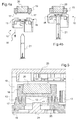
- a valve of the state of the art for regulating a gas flow operates with a magnetic structure 1 and a Hall effect sensor.
- This magnetic structure comprises two magnets 2,3 and two poles 4,5 arranged in a square configuration, said structure 1 being overmolded on a toothed sector 6 forming a quarter circle.
- This arrangement for which the structure 1 emerges from the toothed sector 6 occupies a large volume that is not compatible with the restricted spaces, left available under the hood of a vehicle, around the engine.
- a mounting method according to the invention makes it possible to develop gas control valves, having a small footprint by favoring a positioning of magnets flat, much less space consuming than a salient configuration square.
- This new arrangement of the magnets is made possible thanks to an original bonding technique, allowing to join two elements whose particular geometries make difficult this solidarity by means of usual methods.
- the invention relates to a method of mounting a control valve for controlling the flow of gas in a circuit of a motor vehicle having a heat engine, said valve comprising a magnetic structure, an axis of rotation and a toothed sector.
- the position of the toothed sector is first fixed on the axis of rotation, then the magnetic structure is brought into contact with said sector to be secured thereto by means of a weld.
- the toothed sector comprises an annular groove and the magnetic structure comprises a circular projecting flange, the step of joining being effected by a rotary welding made between said rim and the bottom of said groove.
- a rotary welding made between said rim and the bottom of said groove.
- the method comprises a step of installing a Hall effect fixed probe in the valve, so that the magnetic structure is found between the toothed sector and said probe.
- Said probe is fixed in a given position within the valve, and makes it possible to measure the magnetic field delivered by the magnetic structure caused to pivot and thus to vary the intensity of said field in a given direction.
- the method implements a preliminary step of overmolding the magnetic structure.
- the magnetic structure Before being welded to the toothed sector, the magnetic structure has been manufactured in one piece by overmolding.
- Such a step of manufacturing a plastic part is easy and quick to perform, helping to further simplify the assembly process according to the invention.
- the invention also relates to a control valve for controlling the flow of gas in a circuit of a motor vehicle with a heat engine.
- the main characteristic of said valve is that it is manufactured from a mounting method according to the invention.
- Such a valve may be encountered on any type of gas circuit revolving around the engine, said circuit being for example a cooling circuit of said engine or an EGR loop.
- a valve manufactured by means of a mounting method according to the invention has a small footprint due to a compact arrangement of the parts involved, made possible by the rotary welding technique.
- the magnetic structure comprises a hollow cylindrical base intended to be housed in an annular groove of the toothed sector, said circular base being surmounted by a square-shaped frame in which is placed at least one magnet.
- the frame defines a housing in which each magnet is placed, said frame also serving to protect each of said magnets from any external shock. It is assumed that the diameter The outside of the base is slightly smaller than that of the outer circular wall of the groove.
- Each magnet is placed in the frame without introducing play, so as not to vibrate when the vehicle is in the driving phase.
- the base and the frame are made in one piece by overmolding.
- the base and the frame are made of plastic.
- each magnet has a frustoconical shape. This form of magnet is easy to machine and adapts well to the valve environment.
- said valve constitutes an air intake metering device.
- an air metering unit is placed in an engine air cooling circuit, upstream of said engine, and regulates the incident air flow arriving in the intake manifold.
- valve constitutes a valve controlling the gas flow of an EGR loop.
- An air supply circuit for cooling an engine generally comprises at least one EGR loop which makes it possible to puncture exhaust gases in order to mix them with incident air flowing upstream of said engine.
- the assembly methods according to the invention make it possible to develop gas flow control valves having a small footprint and which are therefore particularly suitable for an air supply circuit for cooling a motor vehicle engine. They also have the advantage of implementing easy and quick steps to perform, such as for example the manufacture of parts by overmolding and the rotary welding operation.
- a valve according to the invention is constituted by an intake air meter 10 placed in the upstream part of an air cooling circuit of a motor vehicle engine.
- This metering device 10 makes it possible to regulate the incident air flow which will come to cool the engine, by adopting several configurations. Indeed, it can be ordered to interrupt said flow when the engine is sufficiently cooled. It can also allow maximum airflow when the vehicle is running at full speed and the engine may be overheated. Finally, it can be set in an intermediate position to allow the passage of a moderate air flow.
- the dispenser 10 schematically comprises a toothed sector 16, comprising a toothed segment 24 in a circular arc, which substantially covers a quarter circle, and a protuberance 11 emerging beyond said toothed sector 16, and composed of two cylindrical parts 12, 13 hollow, arranged concentrically.
- the toothed sector 16 and the protrusion 11 comprising the two cylindrical parts 12, 13 are made in one piece by overmolding.
- the two cylindrical parts 12,13 form between them a free space 14 defining an annular groove.
- the dispenser 10 comprises a magnetic structure 15 having a hollow cylindrical base 17 and surmounted by a frame 18 of substantially rectangular shape.
- Said frame 18 delimits an interior space 19 having a frustoconical geometry and intended to house a frustoconical magnet 20, as shown in FIG. figure 5 .
- the dimensions of said magnet 20 are slightly smaller than those of its accommodating space 19, so that it is inserted inside thereof without leaving any gaps in it. In this way, the magnet 20 remains frozen at the same time. frame 18 and therefore can not vibrate inside thereof.
- the base 17 and the frame 18 are preferably made in one piece by overmolding.
- a Hall effect probe 23 is fixedly placed in the metering device 10 near the magnet 20 housed in the frame 18 of the magnetic structure 15, said magnet 20 being located between said fixed probe 23 and the toothed sector 16 rotary.
- the Hall effect probe which makes it possible to measure the magnetic field produced by the magnetic structure 15, is an indicator of the degree of opening of the flap of the metering device 10 in the air circuit.
- the operation of the metering device 10 is as follows. A signal is sent to an energy source controlling the rotation of the complementary toothed sector, which then initiates a controlled pivoting, resulting in meshing the pivoting of the toothed sector 26 of the metering device 10. The rotation of said toothed sector 26 simultaneously generates that of the magnetic structure 15 which is attached to it, as well as that of the component.
- the Hall effect probe 23, which remains fixed in the metering device 10, thus measures the magnetic field produced by the magnetic structure 15 after its pivoting. With this probe 23, the position of the flap in the cooling circuit is then known.
Landscapes
- Engineering & Computer Science (AREA)
- General Engineering & Computer Science (AREA)
- Chemical & Material Sciences (AREA)
- Mechanical Engineering (AREA)
- Combustion & Propulsion (AREA)
- Analytical Chemistry (AREA)
- Manufacturing & Machinery (AREA)
- Exhaust-Gas Circulating Devices (AREA)
- Electrically Driven Valve-Operating Means (AREA)
- Control Of Throttle Valves Provided In The Intake System Or In The Exhaust System (AREA)
- Transmission And Conversion Of Sensor Element Output (AREA)
Description
- L'invention se rapporte à un procédé de montage d'une vanne de contrôle permettant de réguler le passage de gaz dans un circuit de gaz d'un véhicule automobile.
- Un véhicule automobile doté d'un moteur thermique comprend généralement un circuit de refroidissement d'air, ainsi qu'au moins une boucle EGR (Exhaust Gas Recirculation en langue anglaise) permettant de ponctionner des gaz d'échappement et de les réacheminer en amont du moteur afin qu'ils se mélangent à l'air incident. Ces différents circuits de gaz sont régulés au moyen de vannes pouvant adopter différentes configurations, allant d'une position de fermeture complète à une position d'ouverture maximale, en passant par des positions d'ouverture intermédiaire. L'invention porte sur un procédé optimisé de montage d'une vanne de régulation de gaz, ainsi que sur la vanne issue d'un tel procédé. Un exemple d'une telle vanne est décrite dans le document
EP-1028 239 . - Il est à noter que le terme « vanne » est général, et désigne tout type de dispositif de régulation de gaz au sein d'un circuit de gaz d'un véhicule automobile. Une telle vanne peut par exemple être un doseur d'air d'admission ou une vanne de régulation d'une boucle EGR.
- En se référant aux
figures 1a et 1b , une vanne de l'état de la technique destinée à réguler un flux de gaz fonctionne avec une structure 1 magnétique et un capteur à effet Hall. Cette structure magnétique comporte deux aimants 2,3 et deux pôles 4,5 disposés selon une configuration en carré, ladite structure 1 étant surmoulée sur un secteur denté 6 faisant un quart de cercle. Cette disposition pour laquelle la structure 1 émerge du secteur denté 6 occupe un volume important qui n'est pas compatible avec les espaces restreints, laissés disponibles sous le capot d'un véhicule, autour du moteur. - Un procédé de montage selon l'invention permet d'élaborer des vannes de contrôle de gaz, ayant un encombrement réduit en favorisant un positionnement des aimants à plat, beaucoup moins consommateur de place qu'une configuration saillante en carré. Cette nouvelle disposition des aimants est rendue possible grâce à une technique de liaison originale, permettant de solidariser deux éléments dont les géométries particulières rendent difficile cette solidarisation au moyen de méthodes usuelles.
- L'invention a pour objet un procédé de montage d'une vanne de régulation destinée à contrôler le débit de gaz dans un circuit d'un véhicule automobile doté d'un moteur thermique, ladite vanne comprenant une structure magnétique, un axe de rotation et un secteur denté.
- Le procédé selon l'invention comprend les étapes suivantes :
- Assemblage du secteur denté sur l'axe de rotation,
- Solidarisation par soudage de la structure magnétique sur le secteur denté figé sur l'axe de rotation.
- Ainsi, la position du secteur denté est d'abord figée sur l'axe de rotation, puis la structure magnétique est amenée au contact dudit secteur afin d'être solidarisée à celui-ci au moyen d'une soudure. Ces deux étapes sont simples à réaliser et sont donc rapides à mettre en oeuvre, la technique de soudage étant de plus sûre et fiable pour relier de façon rigide deux éléments entre eux. De plus, cette technique de liaison par soudure ne nécessite pas la présence de pièces d'interface ou de moyens de fixation mécaniques tels que des vis et permet de lier deux éléments entre eux avec une économie de place.
- Avantageusement, le secteur denté comporte une gorge annulaire et la structure magnétique comprend un rebord saillant circulaire, l'étape de solidarisation étant effectuée par un soudage rotatif réalisé entre ledit rebord et le fond de ladite gorge. Autrement dit, l'insertion du rebord dans la gorge permet un pré-positionnement de la structure magnétique sur le secteur denté avant que ladite structure ne soit figée définitivement dans ledit secteur par soudage. Un tel montage, impliquant une étape implicite de guidage, va contribuer à un agencement satisfaisant des pièces entre elles, sans risque de mauvais positionnement avant le soudage. De plus, la pénétration du rebord dans la gorge va abaisser la position de la structure magnétique sur le secteur denté d'une hauteur sensiblement équivalente à la profondeur de ladite gorge, limitant ainsi l'encombrement de ladite structure sur ledit secteur denté. Un soudage rotatif est particulièrement adapté à l'interface de contact annulaire entre la structure magnétique et le secteur denté.
- De façon préférentielle, le procédé comporte une étape d'installation d'une sonde fixe à effet Hall dans la vanne, de manière à ce que la structure magnétique se retrouve entre le secteur denté et ladite sonde. Ladite sonde est figée dans une position donnée au sein de la vanne, et permet de mesurer le champ magnétique délivré par la structure magnétique amenée à pivoter et donc à faire varier l'intensité dudit champ dans une direction donnée.
- De façon avantageuse, le procédé met en oeuvre une étape préalable de surmoulage de la structure magnétique. Avant d'être soudée au secteur denté, la structure magnétique aura été fabriquée en une seule pièce par surmoulage. Une telle étape de fabrication d'une pièce en plastique est facile et rapide à exécuter, contribuant à simplifier davantage encore le procédé de montage selon l'invention.
- L'invention a également pour objet une vanne de régulation destinée à contrôler le débit de gaz dans un circuit d'un véhicule automobile doté d'un moteur thermique. La principale caractéristique de ladite vanne est qu'elle est fabriquée à partir d'un procédé de montage selon l'invention. Une telle vanne peut être rencontrée sur tout type de circuit de gaz gravitant autour du moteur, ledit circuit pouvant être par exemple un circuit de refroidissement dudit moteur ou une boucle EGR. Une vanne fabriquée au moyen d'un procédé de montage selon l'invention possède un encombrement réduit en raison d'un agencement compact des pièces impliquées, rendu possible par la technique de soudage rotatif.
- Avantageusement, la structure magnétique comporte une embase cylindrique creuse, destinée à venir se loger dans une gorge annulaire du secteur denté, ladite embase circulaire étant surmontée d'un cadre de forme carré dans lequel est placé au moins un aimant. Le cadre définit un logement dans lequel est placé chaque aimant, ledit cadre servant également à protéger chacun desdits aimants de tout choc extérieur. Il est supposé que le diamètre extérieur de l'embase est légèrement inférieur à celui de la paroi circulaire extérieure de la gorge. Chaque aimant est placé dans le cadre sans introduire de jeu, de manière à ne pas vibrer lorsque le véhicule est en phase de roulage.
- De façon préférentielle, l'embase et le cadre sont réalisés en une seule pièce par surmoulage. Selon un mode de réalisation préféré d'une vanne selon l'invention, l'embase et le cadre sont réalisés en matière plastique.
- De façon avantageuse, chaque aimant a une forme tronconique. Cette forme d'aimant est facile à usiner et s'adapte bien à l'environnement de la vanne.
- Selon un premier mode de réalisation préféré d'une vanne selon l'invention, ladite vanne constitue un doseur d'admission d'air. Généralement, un doseur d'air est placé dans un circuit de refroidissement en air d'un moteur, en amont dudit moteur, et permet de réguler le flux d'air incident arrivant dans le collecteur d'admission.
- Selon un deuxième mode de réalisation préféré d'une vanne selon l'invention, ladite vanne constitue une vanne contrôlant le débit de gaz d'une boucle EGR. Un circuit d'alimentation en air permettant de refroidir un moteur comporte généralement au moins une boucle EGR qui permet de ponctionner des gaz d'échappement pour les mélanger à de l'air incident circulant en amont dudit moteur.
- Les procédés de montage selon l'invention permettent d'élaborer des vannes de régulation de flux de gaz ayant un encombrement réduit et qui sont donc particulièrement adaptées à un circuit d'alimentation en air destiné à refroidir un moteur de véhicule automobile. Ils ont de plus l'avantage de mettre en oeuvre des étapes faciles et rapides à exécuter, comme par exemple la fabrication de pièces par surmoulage et l'opération de soudage rotatif.
- On donne ci-après une description détaillée d'un mode de réalisation préféré d'une vanne de régulation du débit de gaz selon l'invention, en se référant aux
figures 1 à 5 . - La
figure 1a est une vue en perspective d'un assemblage d'un secteur denté et d'une structure magnétique d'une vanne de l'état de la technique. - La
figure 1b est une vue en coupe axiale longitudinale de l'assemblage de lafigure 1a , - La
figure 2 est une vue en perspective d'un secteur denté d'une vanne selon l'invention, - La
figure 3 est une vue en perspective d'une structure magnétique d'une vanne selon l'invention, - La
figure 4a est une vue en en coupe d'un axe de rotation, d'un secteur denté et d'une structure magnétique d'une vanne selon l'invention, avant montage. - La
figure 4b est une vue en coupe d'un axe de rotation, d'un secteur denté et d'une structure magnétique d'une vanne selon l'invention, après montage. - La
figure 5 est une vue en coupe d'un secteur denté, d'une structure magnétique et d'une sonde d'une vanne selon l'invention. - Les
figures 1a et 1b ont déjà été décrites. - En se référant aux
figures 1 et 2 , une vanne selon l'invention est constituée par un doseur d'air 10 d'admission placé dans la partie amont d'un circuit de refroidissement d'air d'un moteur de véhicule automobile. Ce doseur 10 permet de réguler le flux d'air incident qui va venir refroidir le moteur, en adoptant plusieurs configurations. En effet, il peut être commandé pour interrompre ledit flux lorsque le moteur est suffisamment refroidi. Il peut également autoriser un flux d'air maximal, lorsque le véhicule tourne à plein régime et que le moteur risque d'être en surchauffe. Enfin, il peut être réglé dans une position intermédiaire afin de permettre le passage d'un flux d'air modéré. - En se référant à la
figure 2 , le doseur 10 comporte schématiquement un secteur denté 16, comprenant un segment denté 24 en arc de cercle, qui couvre sensiblement un quart de cercle, et une protubérance 11 émergeant au-delà dudit secteur denté 16, et composée de deux pièces cylindriques 12,13 creuses, disposées de façon concentrique. Le secteur denté 16 et la protubérance 11 comprenant les deux pièces cylindriques 12,13 sont réalisés en une seule pièce par surmoulage. Les deux pièces cylindriques 12,13 ménagent entre elles un espace libre 14 définissant une gorge annulaire. - En se référant à la
figure 3 , le doseur 10 comporte une structure magnétique 15 dotée d'une embase 17 cylindrique creuse et surmontée d'un cadre 18 de forme sensiblement rectangulaire. Ledit cadre 18 délimite un espace intérieur 19 ayant une géométrie tronconique et destiné à loger un aimant tronconique 20, comme le montre lafigure 5 . Les dimensions dudit aimant 20 sont légèrement inférieures à celles de son espace de logement 19, si bien qu'il est inséré à l'intérieur de celui-ci sans laisser subsister de jeu. De cette manière, l'aimant 20 demeure figé à l'intérieur du cadre 18 et ne peut donc pas vibrer à l'intérieur de celui-ci. L'embase 17 et le cadre 18 sont préférentiellement réalisés en une seule pièce par surmoulage. - En se référant aux
figures 4a et 4b , le doseur 10 d'air d'admission possède également un axe de rotation 21 dont est solidaire un volet, non visible sur les figures, ledit volet se retrouvant dans le conduit d'alimentation en air du moteur afin de réguler le flux d'air incident. En effet, le secteur denté 16 du doseur 10 est amené à pivoter sous l'effet d'un secteur denté complémentaire situé à son contact et relié à une unité de commande, cette rotation entrainant celle du volet pour réguler le flux d'air dans le conduit. Un procédé de montage selon l'invention, permettant la fabrication d'un doseur 10 comprend les étapes suivantes : - Le secteur denté 16 est enfilé autour de l'axe de rotation 21, comme l'indique la flèche 22, puis sa position définitive autour dudit axe 21 est figée de façon rigide,
- La structure magnétique 15 est ensuite amenée au contact du secteur denté 16 placé autour de l'axe 21, de manière à ce que l'embase 17 pénètre dans la gorge annulaire 14,
- En se référant aux
figures 4b et 5 , la structure magnétique 15 est solidarisée au secteur denté 16 par une soudure rotative réalisée entre l'embase 17 et le fond de ladite gorge 14, au moyen d'un brin de soudage 25 intercalé entre l'extrémité libre de ladite embase 17 et le fond de ladite gorge 14. - En se référant à la
figure 5 , une sonde à effet Hall 23 est placée de façon fixe dans le doseur 10 à proximité de l'aimant 20 logé dans le cadre 18 de la structure magnétique 15, ledit aimant 20 se retrouvant positionné entre ladite sonde 23 fixe et le secteur denté 16 rotatif. La sonde à effet Hall, qui permet de mesurer le champ magnétique produit par la structure magnétique 15, est un indicateur du degré d'ouverture du volet du doseur 10 dans le circuit d'air. - Le fonctionnement du doseur 10 est le suivant. Un signal est envoyé à une source énergétique pilotant la rotation du secteur denté complémentaire, qui amorce alors un pivotement contrôlé, entraînant par engrènement le pivotement du secteur denté 26 du doseur 10. La rotation dudit secteur denté 26 engendre simultanément celle de la structure magnétique 15 qui lui est rattachée, ainsi que celle du volet. La sonde 23 à effet Hall, qui demeure fixe dans le doseur 10, mesure ainsi le champ magnétique produit par la structure magnétique 15 après son pivotement. Grâce à cette sonde 23, la position du volet dans le circuit de refroidissement est alors connue.
Claims (9)
- Procédé de montage d'une vanne (10) de régulation destinée à contrôler le débit de gaz dans un circuit d'un véhicule automobile doté d'un moteur thermique, ladite vanne (10) comprenant un axe de rotation (21), une structure magnétique (15) comprenant un rebord saillant circulaire (17), et un secteur denté (16) comportant une gorge annulaire (14), caractérisé en qu'il comprend les étapes suivantes :- Assemblage du secteur denté (16) sur l'axe de rotation (21),- Solidarisation par soudage de la structure magnétique (15) sur le secteur denté (16) figé sur l'axe de rotation (21), ledit soudage étant un soudage rotatif réalisé entre ledit rebord (17) et le fond de ladite gorge (14)
- Procédé de montage selon la revendication 1, caractérisé en ce qu'il comporte une étape d'installation d'une sonde fixe (23) à effet Hall dans la vanne (10), de manière à ce que la structure magnétique (15) se retrouve entre le secteur denté (16) et ladite sonde (23).
- Procédé de montage selon l'une quelconque des revendications 1 ou 2, caractérisé en ce qu'il met en oeuvre une étape préalable de surmoulage de la structure magnétique (15).
- Vanne de régulation (10) destinée à contrôler le débit de gaz dans un circuit d'un véhicule automobile doté d'un moteur thermique, caractérisée en ce qu'elle est montée à partir d'un procédé selon l'une quelconque des revendications 1 à 3.
- Vanne de régulation (10) selon la revendication 4, caractérisé en ce que la structure magnétique (15) comporte une embase (17) cylindrique creuse, destinée à venir se loger dans une gorge (14) annulaire du secteur denté (16), et en ce que ladite embase circulaire (17) est surmontée d'un cadre (18) de forme carré dans lequel est placé au moins un aimant (20).
- Vanne de régulation (10) selon la revendication 5, caractérisée en ce que l'embase (17) et le cadre (18) sont réalisés en une seule pièce par surmoulage.
- Vanne de régulation (10) selon l'une quelconque des revendications 5 ou 6, caractérisée en ce que chaque aimant (20) a une forme tronconique.
- Vanne de régulation (10) selon l'une quelconque des revendications 4 à 7, caractérisée en ce qu'elle constitue un doseur d'air d'admission.
- Vanne de régulation (10) selon l'une quelconque des revendications 4 à 7, caractérisée en ce qu'elle constitue une vanne contrôlant le débit de gaz d'une boucle EGR.
Applications Claiming Priority (2)
| Application Number | Priority Date | Filing Date | Title |
|---|---|---|---|
| FR1160861A FR2983249B1 (fr) | 2011-11-28 | 2011-11-28 | Procede de montage d'une vanne de controle d'air |
| PCT/FR2012/052646 WO2013079847A1 (fr) | 2011-11-28 | 2012-11-16 | Procede de montage d'une vanne de controle d'air |
Publications (2)
| Publication Number | Publication Date |
|---|---|
| EP2786000A1 EP2786000A1 (fr) | 2014-10-08 |
| EP2786000B1 true EP2786000B1 (fr) | 2016-04-06 |
Family
ID=47291157
Family Applications (1)
| Application Number | Title | Priority Date | Filing Date |
|---|---|---|---|
| EP12795563.1A Active EP2786000B1 (fr) | 2011-11-28 | 2012-11-16 | Procede de montage d'une vanne de controle d'air |
Country Status (6)
| Country | Link |
|---|---|
| US (1) | US20140305405A1 (fr) |
| EP (1) | EP2786000B1 (fr) |
| JP (1) | JP2015500414A (fr) |
| KR (1) | KR20140097477A (fr) |
| FR (1) | FR2983249B1 (fr) |
| WO (1) | WO2013079847A1 (fr) |
Families Citing this family (5)
| Publication number | Priority date | Publication date | Assignee | Title |
|---|---|---|---|---|
| US10094487B2 (en) | 2013-10-23 | 2018-10-09 | Te Connectivity Corporation | Magnet carrier assembly |
| KR101689783B1 (ko) * | 2015-09-11 | 2016-12-28 | 주식회사 코렌스 | 밸브샤프트 위치감지형 이지알 밸브 |
| JP6759134B2 (ja) * | 2017-03-16 | 2020-09-23 | 株式会社ケーヒン | 回転検出装置 |
| US10920890B2 (en) | 2019-03-07 | 2021-02-16 | Denso International America, Inc. | Air flow leakage control via new valve gear design and assembly process |
| DE102019128868A1 (de) * | 2019-10-25 | 2021-04-29 | Röchling Automotive SE & Co. KG | Aktive Vorrichtung mit Direktantrieb zur Veränderung von aerodynamischen Eigenschaften eines Fahrzeugs |
Family Cites Families (17)
| Publication number | Priority date | Publication date | Assignee | Title |
|---|---|---|---|---|
| US4453097A (en) * | 1982-09-01 | 1984-06-05 | Powertron Division Of Contraves Goerz Corp. | Permanent magnet DC motor with magnets recessed into motor frame |
| FR2643882B1 (fr) * | 1989-03-02 | 1991-05-10 | Cebal | Corps de distributeur, distributeur comportant un tel corps et dome correspondant |
| FR2653757B1 (fr) * | 1989-11-02 | 1992-02-07 | Cebal | Procede de fabrication d'une tete de distributeur, tete et distributeur correspondants. |
| DE9317797U1 (de) * | 1993-11-20 | 1994-02-03 | Ab Elektronik Gmbh, 59368 Werne | Drosselklappenanordnung |
| US6288534B1 (en) * | 1999-02-10 | 2001-09-11 | Cts Corporation | Non-contacting throttle valve position sensor |
| JP2003097299A (ja) * | 2001-09-20 | 2003-04-03 | Hitachi Ltd | 内燃機関の制御弁駆動機構 |
| US20040022464A1 (en) * | 2002-08-05 | 2004-02-05 | Alan Schinazi | Self-aligning bearing assembly with intermediate compliant spherical load ring |
| JP4391065B2 (ja) * | 2002-08-23 | 2009-12-24 | 愛三工業株式会社 | スロットル開度検出装置 |
| FR2844591B1 (fr) * | 2002-09-13 | 2005-04-15 | Arvinmeritor Light Vehicle Sys | Dispositif de determination du deplacement d'un arbre |
| DE102004059625A1 (de) * | 2004-12-10 | 2006-06-22 | Ejot Gmbh & Co. Kg | Reibschweißverbindung zwischen einem Blechteil und einem Rotationskörper |
| US20060255308A1 (en) * | 2005-05-11 | 2006-11-16 | Borgwarner Inc. | Adjustable valve poppet |
| DE102006003806A1 (de) * | 2006-01-26 | 2007-08-02 | Ejot Gmbh & Co. Kg | Befestigungselement zur Reibschweißverbindung mit einem flächigen Bauteil |
| JP2007285173A (ja) * | 2006-04-14 | 2007-11-01 | Denso Corp | バルブ開閉制御装置 |
| US20110278966A1 (en) * | 2006-10-13 | 2011-11-17 | Black & Decker Inc. | Motor With Overmolded Permanent Magnets |
| FR2911942B1 (fr) * | 2007-01-29 | 2009-03-06 | Legris Sa | Procede de raccordement par soudage far friction d'un element et d'une extremite retournee d'un tube multicouche |
| DE102007037215A1 (de) * | 2007-08-07 | 2009-02-12 | Robert Bosch Gmbh | Stellorgan |
| JP2009137387A (ja) * | 2007-12-05 | 2009-06-25 | Koito Mfg Co Ltd | 取付構造及び溶着方法 |
-
2011
- 2011-11-28 FR FR1160861A patent/FR2983249B1/fr active Active
-
2012
- 2012-11-16 KR KR20147017694A patent/KR20140097477A/ko not_active Withdrawn
- 2012-11-16 EP EP12795563.1A patent/EP2786000B1/fr active Active
- 2012-11-16 WO PCT/FR2012/052646 patent/WO2013079847A1/fr not_active Ceased
- 2012-11-16 JP JP2014542915A patent/JP2015500414A/ja active Pending
- 2012-11-16 US US14/360,720 patent/US20140305405A1/en not_active Abandoned
Also Published As
| Publication number | Publication date |
|---|---|
| EP2786000A1 (fr) | 2014-10-08 |
| JP2015500414A (ja) | 2015-01-05 |
| US20140305405A1 (en) | 2014-10-16 |
| FR2983249A1 (fr) | 2013-05-31 |
| KR20140097477A (ko) | 2014-08-06 |
| FR2983249B1 (fr) | 2015-01-09 |
| CN104081026A (zh) | 2014-10-01 |
| WO2013079847A1 (fr) | 2013-06-06 |
Similar Documents
| Publication | Publication Date | Title |
|---|---|---|
| EP2786000B1 (fr) | Procede de montage d'une vanne de controle d'air | |
| EP2742269B1 (fr) | Dispositif de dosage compact | |
| EP3732776B1 (fr) | Motoreducteur a encombrement reduit | |
| FR3072226B1 (fr) | Motoreducteur compact | |
| FR2888888A1 (fr) | Dispositif de recirculation de gaz d'echappement | |
| EP3231068B1 (fr) | Actionneur a encombrement reduit, avec blocage integre du moteur par rapport au boitier | |
| FR2992046A1 (fr) | Vanne de circulation de fluide, notamment pour vehicule automobile | |
| FR2988338A1 (fr) | Dispositif de ventilation | |
| WO2022167747A1 (fr) | Moteur électrique comportant un déflecteur de fluide de refroidissement | |
| FR3024200A1 (fr) | Vanne de circulation de fluide, notamment pour vehicule automobile, a rondelle de butee et procede de fabrication d'une telle vanne | |
| US9851220B2 (en) | Rotational position sensor structure for an intake manifold | |
| WO2015150690A1 (fr) | Vanne à corps de vanne perfectionné et procédé de fabrication d'une telle vanne | |
| EP2342447B1 (fr) | Vanne egr comportant une tole de support | |
| EP3390839B1 (fr) | Hélice pour un groupe moto-ventilateur d'un système de refroidissement d'un moteur de véhicule | |
| FR2980749A1 (fr) | Actionneur pour phare de vehicule | |
| EP3362661B1 (fr) | Vanne motorisée instrumentée | |
| FR2950947A1 (fr) | Vanne destinee, notamment, a etre implantee dans un circuit d'admission d'air d'un moteur thermique | |
| EP3172470A1 (fr) | Vanne de circulation de fluide, notamment pour véhicule automobile, a logement de réception d'une cible de capteur présentant des nervures | |
| EP2850349B1 (fr) | Vanne de circulation de fluide | |
| EP3129626B1 (fr) | Vanne à plot de soutien d'une goulotte électrique | |
| EP3080496B1 (fr) | Plaque de support d'un moteur dans un corps de vanne | |
| EP3134631B1 (fr) | Vanne de circulation de fluide | |
| EP2748497A1 (fr) | Vanne de circulation de fluide a volet mobile | |
| FR3019248A1 (fr) | Vanne a montage facilite d'un attelage dans une came | |
| FR3024201A1 (fr) | Vanne de circulation de fluide, notamment pour vehicule automobile, a surface de siege limitee pour ressort de rappel en torsion |
Legal Events
| Date | Code | Title | Description |
|---|---|---|---|
| PUAI | Public reference made under article 153(3) epc to a published international application that has entered the european phase |
Free format text: ORIGINAL CODE: 0009012 |
|
| 17P | Request for examination filed |
Effective date: 20140428 |
|
| AK | Designated contracting states |
Kind code of ref document: A1 Designated state(s): AL AT BE BG CH CY CZ DE DK EE ES FI FR GB GR HR HU IE IS IT LI LT LU LV MC MK MT NL NO PL PT RO RS SE SI SK SM TR |
|
| DAX | Request for extension of the european patent (deleted) | ||
| GRAP | Despatch of communication of intention to grant a patent |
Free format text: ORIGINAL CODE: EPIDOSNIGR1 |
|
| INTG | Intention to grant announced |
Effective date: 20151007 |
|
| GRAS | Grant fee paid |
Free format text: ORIGINAL CODE: EPIDOSNIGR3 |
|
| GRAA | (expected) grant |
Free format text: ORIGINAL CODE: 0009210 |
|
| RIC1 | Information provided on ipc code assigned before grant |
Ipc: F16K 47/00 20060101ALI20160215BHEP Ipc: F16K 37/00 20060101ALI20160215BHEP Ipc: F02D 9/10 20060101AFI20160215BHEP Ipc: F02M 26/65 20160101ALI20160215BHEP Ipc: F16K 1/48 20060101ALI20160215BHEP Ipc: F02M 26/48 20160101ALI20160215BHEP Ipc: F02M 26/11 20160101ALI20160215BHEP Ipc: F02M 26/53 20160101ALI20160215BHEP |
|
| AK | Designated contracting states |
Kind code of ref document: B1 Designated state(s): AL AT BE BG CH CY CZ DE DK EE ES FI FR GB GR HR HU IE IS IT LI LT LU LV MC MK MT NL NO PL PT RO RS SE SI SK SM TR |
|
| REG | Reference to a national code |
Ref country code: GB Ref legal event code: FG4D Free format text: NOT ENGLISH |
|
| REG | Reference to a national code |
Ref country code: AT Ref legal event code: REF Ref document number: 788093 Country of ref document: AT Kind code of ref document: T Effective date: 20160415 Ref country code: CH Ref legal event code: EP |
|
| REG | Reference to a national code |
Ref country code: IE Ref legal event code: FG4D Free format text: LANGUAGE OF EP DOCUMENT: FRENCH |
|
| REG | Reference to a national code |
Ref country code: DE Ref legal event code: R096 Ref document number: 602012016787 Country of ref document: DE |
|
| REG | Reference to a national code |
Ref country code: LT Ref legal event code: MG4D Ref country code: NL Ref legal event code: MP Effective date: 20160406 |
|
| REG | Reference to a national code |
Ref country code: AT Ref legal event code: MK05 Ref document number: 788093 Country of ref document: AT Kind code of ref document: T Effective date: 20160406 |
|
| PG25 | Lapsed in a contracting state [announced via postgrant information from national office to epo] |
Ref country code: NL Free format text: LAPSE BECAUSE OF FAILURE TO SUBMIT A TRANSLATION OF THE DESCRIPTION OR TO PAY THE FEE WITHIN THE PRESCRIBED TIME-LIMIT Effective date: 20160406 |
|
| PG25 | Lapsed in a contracting state [announced via postgrant information from national office to epo] |
Ref country code: FI Free format text: LAPSE BECAUSE OF FAILURE TO SUBMIT A TRANSLATION OF THE DESCRIPTION OR TO PAY THE FEE WITHIN THE PRESCRIBED TIME-LIMIT Effective date: 20160406 Ref country code: IS Free format text: LAPSE BECAUSE OF FAILURE TO SUBMIT A TRANSLATION OF THE DESCRIPTION OR TO PAY THE FEE WITHIN THE PRESCRIBED TIME-LIMIT Effective date: 20160806 Ref country code: PL Free format text: LAPSE BECAUSE OF FAILURE TO SUBMIT A TRANSLATION OF THE DESCRIPTION OR TO PAY THE FEE WITHIN THE PRESCRIBED TIME-LIMIT Effective date: 20160406 Ref country code: LT Free format text: LAPSE BECAUSE OF FAILURE TO SUBMIT A TRANSLATION OF THE DESCRIPTION OR TO PAY THE FEE WITHIN THE PRESCRIBED TIME-LIMIT Effective date: 20160406 Ref country code: NO Free format text: LAPSE BECAUSE OF FAILURE TO SUBMIT A TRANSLATION OF THE DESCRIPTION OR TO PAY THE FEE WITHIN THE PRESCRIBED TIME-LIMIT Effective date: 20160706 |
|
| PG25 | Lapsed in a contracting state [announced via postgrant information from national office to epo] |
Ref country code: PT Free format text: LAPSE BECAUSE OF FAILURE TO SUBMIT A TRANSLATION OF THE DESCRIPTION OR TO PAY THE FEE WITHIN THE PRESCRIBED TIME-LIMIT Effective date: 20160808 Ref country code: ES Free format text: LAPSE BECAUSE OF FAILURE TO SUBMIT A TRANSLATION OF THE DESCRIPTION OR TO PAY THE FEE WITHIN THE PRESCRIBED TIME-LIMIT Effective date: 20160406 Ref country code: AT Free format text: LAPSE BECAUSE OF FAILURE TO SUBMIT A TRANSLATION OF THE DESCRIPTION OR TO PAY THE FEE WITHIN THE PRESCRIBED TIME-LIMIT Effective date: 20160406 Ref country code: HR Free format text: LAPSE BECAUSE OF FAILURE TO SUBMIT A TRANSLATION OF THE DESCRIPTION OR TO PAY THE FEE WITHIN THE PRESCRIBED TIME-LIMIT Effective date: 20160406 Ref country code: LV Free format text: LAPSE BECAUSE OF FAILURE TO SUBMIT A TRANSLATION OF THE DESCRIPTION OR TO PAY THE FEE WITHIN THE PRESCRIBED TIME-LIMIT Effective date: 20160406 Ref country code: GR Free format text: LAPSE BECAUSE OF FAILURE TO SUBMIT A TRANSLATION OF THE DESCRIPTION OR TO PAY THE FEE WITHIN THE PRESCRIBED TIME-LIMIT Effective date: 20160707 Ref country code: SE Free format text: LAPSE BECAUSE OF FAILURE TO SUBMIT A TRANSLATION OF THE DESCRIPTION OR TO PAY THE FEE WITHIN THE PRESCRIBED TIME-LIMIT Effective date: 20160406 Ref country code: RS Free format text: LAPSE BECAUSE OF FAILURE TO SUBMIT A TRANSLATION OF THE DESCRIPTION OR TO PAY THE FEE WITHIN THE PRESCRIBED TIME-LIMIT Effective date: 20160406 |
|
| REG | Reference to a national code |
Ref country code: FR Ref legal event code: PLFP Year of fee payment: 5 |
|
| PG25 | Lapsed in a contracting state [announced via postgrant information from national office to epo] |
Ref country code: IT Free format text: LAPSE BECAUSE OF FAILURE TO SUBMIT A TRANSLATION OF THE DESCRIPTION OR TO PAY THE FEE WITHIN THE PRESCRIBED TIME-LIMIT Effective date: 20160406 |
|
| REG | Reference to a national code |
Ref country code: DE Ref legal event code: R097 Ref document number: 602012016787 Country of ref document: DE |
|
| PG25 | Lapsed in a contracting state [announced via postgrant information from national office to epo] |
Ref country code: DK Free format text: LAPSE BECAUSE OF FAILURE TO SUBMIT A TRANSLATION OF THE DESCRIPTION OR TO PAY THE FEE WITHIN THE PRESCRIBED TIME-LIMIT Effective date: 20160406 Ref country code: CZ Free format text: LAPSE BECAUSE OF FAILURE TO SUBMIT A TRANSLATION OF THE DESCRIPTION OR TO PAY THE FEE WITHIN THE PRESCRIBED TIME-LIMIT Effective date: 20160406 Ref country code: EE Free format text: LAPSE BECAUSE OF FAILURE TO SUBMIT A TRANSLATION OF THE DESCRIPTION OR TO PAY THE FEE WITHIN THE PRESCRIBED TIME-LIMIT Effective date: 20160406 Ref country code: RO Free format text: LAPSE BECAUSE OF FAILURE TO SUBMIT A TRANSLATION OF THE DESCRIPTION OR TO PAY THE FEE WITHIN THE PRESCRIBED TIME-LIMIT Effective date: 20160406 Ref country code: SK Free format text: LAPSE BECAUSE OF FAILURE TO SUBMIT A TRANSLATION OF THE DESCRIPTION OR TO PAY THE FEE WITHIN THE PRESCRIBED TIME-LIMIT Effective date: 20160406 |
|
| PLBE | No opposition filed within time limit |
Free format text: ORIGINAL CODE: 0009261 |
|
| STAA | Information on the status of an ep patent application or granted ep patent |
Free format text: STATUS: NO OPPOSITION FILED WITHIN TIME LIMIT |
|
| PG25 | Lapsed in a contracting state [announced via postgrant information from national office to epo] |
Ref country code: SM Free format text: LAPSE BECAUSE OF FAILURE TO SUBMIT A TRANSLATION OF THE DESCRIPTION OR TO PAY THE FEE WITHIN THE PRESCRIBED TIME-LIMIT Effective date: 20160406 Ref country code: BE Free format text: LAPSE BECAUSE OF NON-PAYMENT OF DUE FEES Effective date: 20161130 |
|
| 26N | No opposition filed |
Effective date: 20170110 |
|
| PG25 | Lapsed in a contracting state [announced via postgrant information from national office to epo] |
Ref country code: SI Free format text: LAPSE BECAUSE OF FAILURE TO SUBMIT A TRANSLATION OF THE DESCRIPTION OR TO PAY THE FEE WITHIN THE PRESCRIBED TIME-LIMIT Effective date: 20160406 |
|
| REG | Reference to a national code |
Ref country code: CH Ref legal event code: PL |
|
| GBPC | Gb: european patent ceased through non-payment of renewal fee |
Effective date: 20161116 |
|
| PG25 | Lapsed in a contracting state [announced via postgrant information from national office to epo] |
Ref country code: LI Free format text: LAPSE BECAUSE OF NON-PAYMENT OF DUE FEES Effective date: 20161130 Ref country code: CH Free format text: LAPSE BECAUSE OF NON-PAYMENT OF DUE FEES Effective date: 20161130 |
|
| REG | Reference to a national code |
Ref country code: IE Ref legal event code: MM4A |
|
| PG25 | Lapsed in a contracting state [announced via postgrant information from national office to epo] |
Ref country code: LU Free format text: LAPSE BECAUSE OF NON-PAYMENT OF DUE FEES Effective date: 20161130 |
|
| PG25 | Lapsed in a contracting state [announced via postgrant information from national office to epo] |
Ref country code: IE Free format text: LAPSE BECAUSE OF NON-PAYMENT OF DUE FEES Effective date: 20161116 Ref country code: GB Free format text: LAPSE BECAUSE OF NON-PAYMENT OF DUE FEES Effective date: 20161116 |
|
| REG | Reference to a national code |
Ref country code: FR Ref legal event code: PLFP Year of fee payment: 6 |
|
| REG | Reference to a national code |
Ref country code: BE Ref legal event code: MM Effective date: 20161130 |
|
| PG25 | Lapsed in a contracting state [announced via postgrant information from national office to epo] |
Ref country code: HU Free format text: LAPSE BECAUSE OF FAILURE TO SUBMIT A TRANSLATION OF THE DESCRIPTION OR TO PAY THE FEE WITHIN THE PRESCRIBED TIME-LIMIT; INVALID AB INITIO Effective date: 20121116 |
|
| PG25 | Lapsed in a contracting state [announced via postgrant information from national office to epo] |
Ref country code: MC Free format text: LAPSE BECAUSE OF FAILURE TO SUBMIT A TRANSLATION OF THE DESCRIPTION OR TO PAY THE FEE WITHIN THE PRESCRIBED TIME-LIMIT Effective date: 20160406 Ref country code: MK Free format text: LAPSE BECAUSE OF FAILURE TO SUBMIT A TRANSLATION OF THE DESCRIPTION OR TO PAY THE FEE WITHIN THE PRESCRIBED TIME-LIMIT Effective date: 20160406 Ref country code: CY Free format text: LAPSE BECAUSE OF FAILURE TO SUBMIT A TRANSLATION OF THE DESCRIPTION OR TO PAY THE FEE WITHIN THE PRESCRIBED TIME-LIMIT Effective date: 20160406 |
|
| PG25 | Lapsed in a contracting state [announced via postgrant information from national office to epo] |
Ref country code: BG Free format text: LAPSE BECAUSE OF FAILURE TO SUBMIT A TRANSLATION OF THE DESCRIPTION OR TO PAY THE FEE WITHIN THE PRESCRIBED TIME-LIMIT Effective date: 20160406 |
|
| PG25 | Lapsed in a contracting state [announced via postgrant information from national office to epo] |
Ref country code: MT Free format text: LAPSE BECAUSE OF FAILURE TO SUBMIT A TRANSLATION OF THE DESCRIPTION OR TO PAY THE FEE WITHIN THE PRESCRIBED TIME-LIMIT Effective date: 20160406 |
|
| PG25 | Lapsed in a contracting state [announced via postgrant information from national office to epo] |
Ref country code: AL Free format text: LAPSE BECAUSE OF FAILURE TO SUBMIT A TRANSLATION OF THE DESCRIPTION OR TO PAY THE FEE WITHIN THE PRESCRIBED TIME-LIMIT Effective date: 20160406 Ref country code: TR Free format text: LAPSE BECAUSE OF FAILURE TO SUBMIT A TRANSLATION OF THE DESCRIPTION OR TO PAY THE FEE WITHIN THE PRESCRIBED TIME-LIMIT Effective date: 20160406 |
|
| P01 | Opt-out of the competence of the unified patent court (upc) registered |
Effective date: 20230528 |
|
| PGFP | Annual fee paid to national office [announced via postgrant information from national office to epo] |
Ref country code: DE Payment date: 20251117 Year of fee payment: 14 |
|
| PGFP | Annual fee paid to national office [announced via postgrant information from national office to epo] |
Ref country code: FR Payment date: 20251128 Year of fee payment: 14 |