EP2786049B1 - Déverrouillage d'urgence d'une boîte de vitesses - Google Patents
Déverrouillage d'urgence d'une boîte de vitesses Download PDFInfo
- Publication number
- EP2786049B1 EP2786049B1 EP12794873.5A EP12794873A EP2786049B1 EP 2786049 B1 EP2786049 B1 EP 2786049B1 EP 12794873 A EP12794873 A EP 12794873A EP 2786049 B1 EP2786049 B1 EP 2786049B1
- Authority
- EP
- European Patent Office
- Prior art keywords
- vehicle
- transmission
- actuating lever
- receptacle
- emergency unlocking
- Prior art date
- Legal status (The legal status is an assumption and is not a legal conclusion. Google has not performed a legal analysis and makes no representation as to the accuracy of the status listed.)
- Active
Links
Images

Classifications
-
- B—PERFORMING OPERATIONS; TRANSPORTING
- B60—VEHICLES IN GENERAL
- B60W—CONJOINT CONTROL OF VEHICLE SUB-UNITS OF DIFFERENT TYPE OR DIFFERENT FUNCTION; CONTROL SYSTEMS SPECIALLY ADAPTED FOR HYBRID VEHICLES; ROAD VEHICLE DRIVE CONTROL SYSTEMS FOR PURPOSES NOT RELATED TO THE CONTROL OF A PARTICULAR SUB-UNIT
- B60W10/00—Conjoint control of vehicle sub-units of different type or different function
- B60W10/18—Conjoint control of vehicle sub-units of different type or different function including control of braking systems
- B60W10/182—Conjoint control of vehicle sub-units of different type or different function including control of braking systems including control of parking brakes
-
- F—MECHANICAL ENGINEERING; LIGHTING; HEATING; WEAPONS; BLASTING
- F16—ENGINEERING ELEMENTS AND UNITS; GENERAL MEASURES FOR PRODUCING AND MAINTAINING EFFECTIVE FUNCTIONING OF MACHINES OR INSTALLATIONS; THERMAL INSULATION IN GENERAL
- F16H—GEARING
- F16H63/00—Control outputs from the control unit to change-speed- or reversing-gearings for conveying rotary motion or to other devices than the final output mechanism
- F16H63/02—Final output mechanisms therefor; Actuating means for the final output mechanisms
- F16H63/30—Constructional features of the final output mechanisms
- F16H63/34—Locking or disabling mechanisms
- F16H63/3416—Parking lock mechanisms or brakes in the transmission
- F16H63/3491—Emergency release or engagement of parking locks or brakes
-
- B—PERFORMING OPERATIONS; TRANSPORTING
- B60—VEHICLES IN GENERAL
- B60W—CONJOINT CONTROL OF VEHICLE SUB-UNITS OF DIFFERENT TYPE OR DIFFERENT FUNCTION; CONTROL SYSTEMS SPECIALLY ADAPTED FOR HYBRID VEHICLES; ROAD VEHICLE DRIVE CONTROL SYSTEMS FOR PURPOSES NOT RELATED TO THE CONTROL OF A PARTICULAR SUB-UNIT
- B60W10/00—Conjoint control of vehicle sub-units of different type or different function
- B60W10/10—Conjoint control of vehicle sub-units of different type or different function including control of change-speed gearings
- B60W10/11—Stepped gearings
-
- F—MECHANICAL ENGINEERING; LIGHTING; HEATING; WEAPONS; BLASTING
- F16—ENGINEERING ELEMENTS AND UNITS; GENERAL MEASURES FOR PRODUCING AND MAINTAINING EFFECTIVE FUNCTIONING OF MACHINES OR INSTALLATIONS; THERMAL INSULATION IN GENERAL
- F16H—GEARING
- F16H59/00—Control inputs to control units of change-speed- or reversing-gearings for conveying rotary motion
- F16H59/02—Selector apparatus
- F16H59/08—Range selector apparatus
- F16H59/10—Range selector apparatus comprising levers
-
- Y—GENERAL TAGGING OF NEW TECHNOLOGICAL DEVELOPMENTS; GENERAL TAGGING OF CROSS-SECTIONAL TECHNOLOGIES SPANNING OVER SEVERAL SECTIONS OF THE IPC; TECHNICAL SUBJECTS COVERED BY FORMER USPC CROSS-REFERENCE ART COLLECTIONS [XRACs] AND DIGESTS
- Y10—TECHNICAL SUBJECTS COVERED BY FORMER USPC
- Y10T—TECHNICAL SUBJECTS COVERED BY FORMER US CLASSIFICATION
- Y10T74/00—Machine element or mechanism
- Y10T74/20—Control lever and linkage systems
- Y10T74/20012—Multiple controlled elements
- Y10T74/20018—Transmission control
- Y10T74/20085—Restriction of shift, gear selection, or gear engagement
- Y10T74/20098—Separate actuator to disengage restrictor
Definitions
- the invention relates to a gearbox door unlocking for a mechanically locked automatic parking gear engaged automatic transmission, with a manually operable actuator for mechanically deactivating the parking stage.
- Automatic transmissions for motor vehicles have an operating range which is subdivided into various manually preselectable operating levels, which are referred to as speed steps.
- the driving levels also include the parking level (parking position) and the neutral position.
- Driving steps of an automatic transmission are selected by the driver on a control unit, whereby electrohydraulic actuators are inserted in the automatic transmission.
- the parking level is engaged, the automatic transmission is mechanically locked, so that the vehicle can not be towed in the event of a power failure or if the associated electronic control unit malfunctions. To release this lock, a mechanical emergency release must be actuated.
- the same problem also exists in newer automatic transmissions, in which operator inputs of the driver via a shift-by-wire control element are electronically transmitted to the automatic transmission.
- a speed selector is known with an emergency operation for a parking brake having a Bowden cable, the connected to a lever.
- a tensile force is exerted on the Bowden cable, so that the lever is pivoted and releases the automatic transmission.
- the cable must be operated with a force that can not be applied manually, so a force transmission must be integrated into the emergency release.
- the footbrake In order to prevent uncontrolled rolling away of the vehicle when the emergency release is actuated, the footbrake must be stepped on at the same time. Therefore, the emergency release must be in the gripping area of the driver.
- the emergency release To limit the cable length, the emergency release must be positioned near the gearbox. Accordingly, only a few positions in the vehicle are suitable for accommodating the gearbox door unlocking.
- the transmission is in the front of the vehicle, the emergency release is conveniently placed in the driver's footwell. If the transmission is in the rear, the emergency release is conveniently placed in the center console or next to the driver's seat or in a two-seater in the parcel shelf.
- the invention is therefore based on the object to provide a gearbox door unlocking, the installation space is reduced.
- the actuator has a vehicle-mounted recording with a power transmission element and an actuating lever which is used to disable the parking in the vehicle-mounted recording to disable the parking stage by means of the power transmission element.
- the invention is based on the recognition that a large part of the required space can be saved in critical areas by the actuator is formed in two parts and a vehicle-mounted recording and a separate operating lever, which only when needed, that is to perform an emergency release of the transmission , is used in the vehicle-mounted recording. During normal operation, the operating lever may be stowed elsewhere in the vehicle.
- the space-consuming mechanics in the form of the actuating lever projects only during an emergency release of the transmission limited in time in the passenger compartment and is otherwise part of the tool kit. This results, for example, additional shelves in the center console.
- the actuating lever can be positively coupled with the vehicle-fixed receptacle.
- the force required for the unlocking force can be applied and transmitted to the power transmission element.
- a particularly space-saving attachment is obtained when the vehicle-fixed recording of the gearbox release according to the invention has a tab into which a portion of the actuating lever formed in the same manner can be inserted.
- This tab only requires a small space, so that the vehicle interior is not unnecessarily impaired.
- the actuating lever has a locking element which can be inserted into a vehicle-fixed opening.
- This opening may be formed in particular as a groove or hole.
- a tie rod connected to a cable is arranged in the receptacle, which can be positively coupled with the actuating lever during insertion of the actuating lever into the receptacle and / or non-positively.
- the coupling is preferably formed automatically when inserting the operating lever.
- the actuating lever comprises a hand crank and preferably a power transmission for reducing the manually applied actuation force. In this way, an emergency release with little effort by a user can be performed.
- the actuating lever has a form-fitting coupled to the vehicle-mounted receptacle slide which can be coupled with a lever handle to disable the parking stage by means arranged in the recording, connected to a cable tie rods.
- the actuating lever has an external thread and / or a pin, whereby the actuating lever is guided by means of an internal thread and / or a backdrop of the housing.
- the thread is formed so that no self-locking arises.
- the coupled to the operating lever carriage is rotatably supported on the housing and axially displaceable. It is rotatably mounted on the actuating lever and is entrained in an axial movement of the actuating handle. When the operating lever is rotated, it moves axially upwards over the thread and / or the link and pulls the carriage with the tie rod, whereby the parking stage is deactivated by means of the force transmission element.
- a further development of the invention can provide that the actuating lever can be fixed in an end position when the actuating element is actuated (triggered).
- the backdrop of the housing is designed so that the pin of the actuating lever locked in the end position. The user thus receives a feedback so that he can recognize when the parking level has been deactivated and the transmission has been unlocked.
- a development may provide that the gearbox door unlocking can be converted back to the starting position by applying a force on the part of the user and the support of a return spring.
- a pin or ejector is provided in the lock of the emergency release, which presses the pin from the end position when pushing the latch.
- the locked position is released again, the carriage is moved downwards and the deactivation of the parking stage is canceled again.
- an electrified variant is possible.
- This has an integrated electric motor, which is powered by an accumulator with energy.
- a push button is provided on the actuating element, by which an actuating handle or an actuating lever is replaced.
- This electrical variant is used as the manually operated variant in the vehicle-mounted recording and locked.
- the electric motor moves a component that pulls up the carriage, thereby deactivating the parking stage.
- the accumulator provides the necessary energy for the operation when the vehicle electrical system has failed.
- a high-performance accumulator such as a lithium-ion battery, which ensures a multi-year working life is suitable.
- the gearbox release is primarily intended for such cases when the entire vehicle electrical system has failed. However, if the vehicle electrical system has only partially failed in the event of a fault, or if the automatic transmission is locked for another reason, connection of the gearbox emergency release according to the invention to the vehicle electrical system is likewise conceivable as a power source in addition to the integrated battery.
- the gearbox door unlocking has a corresponding electrical connection, for example a contact point.
- the actuator has a corresponding mating contact point and a wiring for the power supply to the electric motor.
- the integrated accumulator serves only as an "emergency solution".
- an electrical decoupling can be provided between the gearbox door unlocking and the automatic transmission.
- the electric emergency release mechanism may be located outside the cab near the automatic transmission.
- the driver can operate the remote control from the passenger compartment. This sends a signal to the emergency release, whereby the integrated electric motor, the power transmission element, in particular draws a cable, whereby the parking level is deactivated.
- a transmitter and a receiver are required at the emergency release to receive the signal from the remote control and to send back a corresponding signal after unlocking the automatic transmission. This allows the driver to receive feedback via a warning lamp after the parking stage of the automatic transmission has been deactivated.
- the invention relates to a motor vehicle.
- the motor vehicle according to the invention has a gearbox door unlocking of the type described.
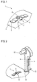
- Fig. 1 is a perspective view of a vehicle-mounted receptacle 1 as part of an actuating element of a gearbox door unlocking for an automatic transmission of a motor vehicle.
- the vehicle-mounted receptacle comprises a tab 2, which is angled relative to a mounting portion 3.
- the attachment portion 3 is fixedly connected to a vehicle body 4, in the illustrated embodiment, it is welded. Between the vehicle body 4 and the mounting portion 3, a free space is formed, in which an actuating element can be inserted.
- the vehicle-mounted receptacle 1 is symmetrical, in the middle it faces a one-sided opening 5, in which the actuating element can be used.
- the one-sided opening 5 is formed as a rectangular recess of the tab 2.
- a tie rod 6 which is T-shaped and is connected at its lower end with a cable 7.
- the cable 7 is part of a Bowden cable whose other end is attached to an automatic transmission, so that the parking stage of the automatic transmission can be deactivated by a force acting on the tie rod 6 traction.
- a vehicle-fixed opening is provided which is formed as a groove 8.
- a trained as an actuating lever actuator can be used and locked.
- Fig. 2 shows the vehicle-mounted receptacle 1 and an actuating lever 9.
- the actuating lever 9 includes a crank 10 to exert a tensile force on the tie rod 6 in the coupled state.
- the operating lever 9 has front and rear foot sections 12, 13, whose shape and size is adapted to the tab 2.
- the foot portions 12, 13 can be pushed laterally into the space between the tab 2 and the vehicle body 4 until the operating lever 9 is in the opening 5. Subsequently, a lock 11 can be pressed into the groove 8 in order to positively couple the actuating lever 9 with the vehicle-mounted receptacle 1.
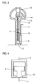
- the crank 10 is connected via a translation 14 with a cable 15, which has a carriage 16 at its lower end.
- a cable 15 which has a carriage 16 at its lower end.
- the crank 10 When turning the crank 10 is pulled over the translation 14 of the cable 15 together with the attached carriage 16 upwards, whereby a tensile force is exerted on the tie rod 6 and connected to this cable 7.
- the actuating lever 9 In order to prevent the carriage 16 from snapping back when the crank 10 is released, the actuating lever 9 has a wedge brake 17.
- the carriage 16 before performing a gearbox release in the in Fig. 3 is shown starting position, a return spring 18 is mounted above the carriage 16, which presses the carriage 16 down. When turning the crank 10, the force of the spring 18 is overcome and the carriage 16 is pulled upwards.
- the crank 10 has a locking pin to lock the crank 10 in the final position after deactivating the parking stage.
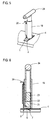
- FIGS. 5 and 6 show a second embodiment of the essential components of a Getriebeotentriegelung.
- the fixed vehicle seat 1 mounted on the vehicle body 4 substantially corresponds to that of the first embodiment.
- the actuating element comprises a tubular housing 19 which can be inserted into the tab 20.
- a lock 20 On one side of the housing 19 is a lock 20, which can be pressed down after the shoeing into the groove 8 in order to positively connect the actuating element with the vehicle-mounted receptacle 1.
- a carriage 21 which is rotatably received in the housing 19.
- arms or projections 22 are provided which prevent a rotation of the carriage 21 relative to the housing 19.
- An upper portion of the carriage 21 has an external thread 23.
- the actuator further comprises a hollow handle 24 with an internal thread screwed onto the external thread 23 of the carriage 21.
- the actuator which consists essentially of the housing 19 and the handle 24, is used only for carrying out a gearbox door unlocking in the vehicle-mounted receptacle 1, otherwise it is stowed at a different location in the vehicle, for example, the tool on board.
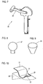
- Fig. 7 shows an embodiment of a differently constructed operating lever. Basically, the in Fig. 7 shown actuating lever 25, the actuating lever 9 of the first embodiment. However, the operating lever 25 has a handle 26 with a longer lever arm, which in addition to the translation, the operating forces are reduced.
- FIGS. 8 and 9 represent alternative embodiments of a tie rod.
- Fig. 8 shows a tie rod 27 with a ball head, which can be received by a correspondingly shaped carriage.
- Fig. 9 a pear-shaped tie rod 28 which can also be taken up and pulled by a correspondingly shaped carriage.
- tie rods is a form-fitting, but there are also other designs with a positive recording of the tie rod in the carriage conceivable.
- Fig. 10 shows an alternative embodiment of a vehicle-mounted receptacle 29.
- the vehicle-mounted receptacle 29 is mounted in the region of a tunnel 30 of a vehicle body and integrated into an already existing body component 31.
- the vehicle-fixed receptacle 29 - analogous to that in Fig. 1 shown receptacle - an opening 32 and an angled tab 33, whereby a free space is formed, in which an actuating element is einschuhbar.
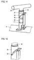
- Fig. 11 shows an embodiment of a gearbox release, with an actuating lever 34 having an external thread 35 which cooperates with an internal thread of a housing 36.
- the external thread 35 and the internal thread 37 are formed so that no self-locking occurs.
- the housing 36 includes a gate 38 which extends helically and in which a pin 39 of the actuating lever 34 is guided.
- a carriage 40 is rotatably mounted on the actuating lever 34, the carriage 40 is rotationally fixed relative to the housing 36 and axially displaceable.
- the operating lever 34 When the operating lever 34 is rotated by a user, it is moved axially away from the vehicle body 4 (upwards) by means of the intermeshing threads 35, 37 and the peg 38 running in the link 38.
- a tie rod is attached, which is pulled up, thereby deactivating the parking stage.
- a spring element 41 is arranged, which generates upon release of the actuating lever 34, a restoring force by which the actuating lever 34 is moved back to the starting position.
- Fig. 12 shows the area of the gate 38 of the housing 36 in an enlarged scale.
- the pin 39 in its initial position, that is in the non-actuated state in which the parking stage is activated.
- the pin 39 is moved by the rotation of the operating lever 34 along the link 38, as indicated by the double arrow.
- Fig. 13 shows together with Fig. 14 the end position after the pin 39 has reached the upper end of the link 38. At the upper end of the gate 38, this has a projecting latching portion 42, behind which the pin 39 engages. This engagement is perceived by the user so that he can recognize that the operating lever 34 is in the locking position.
Landscapes
- Engineering & Computer Science (AREA)
- General Engineering & Computer Science (AREA)
- Mechanical Engineering (AREA)
- Chemical & Material Sciences (AREA)
- Combustion & Propulsion (AREA)
- Transportation (AREA)
- Gear-Shifting Mechanisms (AREA)
- Lock And Its Accessories (AREA)
Claims (9)
- Déverrouillage d'urgence de boîte de vitesses pour une boîte de vitesses automatique bloquée mécaniquement lorsque la position de stationnement est engagée, avec un élément d'actionnement actionnable manuellement pour la désactivation mécanique de la position de stationnement, qui présente un logement (1, 29) fixé au véhicule avec un élément de transmission de force, et un levier d'actionnement (9, 25, 34) qui peut être inséré pour la désactivation de la position de stationnement dans le logement (1, 29) fixé au véhicule afin de désactiver la position de stationnement à l'aide de l'élément de transmission de force,
caractérisé en ce
qu'un tirant (6, 27, 28) relié à un câble de traction (7) est agencé dans le logement (1, 29), lequel tirant peut être couplé lors de l'insertion du levier d'actionnement (9, 25) dans le logement (1, 29) par complémentarité de formes et/ou à force au levier d'actionnement (9, 25, 34). - Déverrouillage d'urgence de boîte de vitesses selon la revendication 1,
caractérisé en ce
que le levier d'actionnement (9, 25) peut être couplé par complémentarité de formes au logement (1, 29) fixé au véhicule. - Déverrouillage d'urgence de boîte de vitesses selon la revendication 1 ou 2,
caractérisé en ce
que le logement (1, 29) fixé au véhicule présente une languette (2, 33), dans laquelle une section formée de préférence de manière diamétralement opposée du levier d'actionnement (9, 25) peut être insérée. - Déverrouillage d'urgence de boîte de vitesses selon l'une quelconque des revendications précédentes,
caractérisé en ce
que le levier d'actionnement (9, 25) présente un élément de verrouillage (11, 20, 43) qui peut être inséré dans une ouverture fixée au véhicule qui est réalisée en particulier comme une rainure (8) ou comme un trou. - Déverrouillage d'urgence de boîte de vitesses selon l'une quelconque des revendications précédentes,
caractérisé en ce
que le levier d'actionnement (9) comporte une manivelle (10) et de préférence une transmission de force pour la diminution de la force d'actionnement applicable manuellement. - Déverrouillage d'urgence de boîte de vitesses selon l'une quelconque des revendications 1 à 4,
caractérisé en ce
que le levier d'actionnement présente un chariot (21, 40) pouvant être couplé par complémentarité de formes au logement (1) fixé au véhicule, lequel chariot peut être couplé à une poignée de levier (24, 34) afin de désactiver la position de stationnement à l'aide du tirant (6, 27, 28) relié au câble de traction (7), agencé dans le logement. - Déverrouillage d'urgence de boîte de vitesses selon la revendication 6,
caractérisé en ce
que le levier d'actionnement présente un filet extérieur et/ou un tenon qui est guidé à l'aide d'un filet intérieur et/ou à l'aide d'une coulisse dans un boîtier. - Déverrouillage d'urgence de boîte de vitesses selon la revendication 6 ou 7,
caractérisé en ce
que le levier d'actionnement peut être fixé dans une position d'extrémité après le détachement de l'élément de transmission de force. - Véhicule automobile avec une boîte de vitesses automatique,
caractérisé en ce
que la boîte de vitesses automatique présente un déverrouillage d'urgence de boîte de vitesses selon l'une quelconque des revendications 1 à 8.
Applications Claiming Priority (2)
| Application Number | Priority Date | Filing Date | Title |
|---|---|---|---|
| DE102011119747A DE102011119747A1 (de) | 2011-11-30 | 2011-11-30 | Getriebenotentriegelung |
| PCT/EP2012/004870 WO2013079182A1 (fr) | 2011-11-30 | 2012-11-24 | Déverrouillage d'urgence d'une boîte de vitesses |
Publications (2)
| Publication Number | Publication Date |
|---|---|
| EP2786049A1 EP2786049A1 (fr) | 2014-10-08 |
| EP2786049B1 true EP2786049B1 (fr) | 2016-02-03 |
Family
ID=47278755
Family Applications (1)
| Application Number | Title | Priority Date | Filing Date |
|---|---|---|---|
| EP12794873.5A Active EP2786049B1 (fr) | 2011-11-30 | 2012-11-24 | Déverrouillage d'urgence d'une boîte de vitesses |
Country Status (5)
| Country | Link |
|---|---|
| US (1) | US9592819B2 (fr) |
| EP (1) | EP2786049B1 (fr) |
| CN (1) | CN103958945B (fr) |
| DE (1) | DE102011119747A1 (fr) |
| WO (1) | WO2013079182A1 (fr) |
Families Citing this family (21)
| Publication number | Priority date | Publication date | Assignee | Title |
|---|---|---|---|---|
| GB201204325D0 (en) | 2012-03-12 | 2012-04-25 | Jaguar Cars | Park release method and vehicle having park release means |
| GB2525038B (en) * | 2014-04-11 | 2018-05-30 | Jaguar Land Rover Ltd | Extendable lever for vehicle release mechanism |
| EP3317150B1 (fr) * | 2015-07-02 | 2019-10-09 | Kongsberg Driveline Systems I, Inc. | Dispositif manuel de libération de stationnement pour véhicule |
| WO2017182555A1 (fr) * | 2016-04-21 | 2017-10-26 | Küster Holding GmbH | Actionneur et dispositif pour actionner un frein de stationnement d'une boîte de vitesses automatique de véhicule automobile à l'aide d'un actionneur de ce type ainsi que véhicule automobile équipé de ce dispositif |
| DE102016214585A1 (de) * | 2016-08-05 | 2018-02-08 | Zf Friedrichshafen Ag | Getriebe und Parksperrenentriegelungseinrichtung |
| DE102016214591A1 (de) * | 2016-08-05 | 2018-02-08 | Zf Friedrichshafen Ag | Getriebe und Parksperrenentriegelungseinrichtung |
| DE102016214587A1 (de) * | 2016-08-05 | 2018-02-08 | Zf Friedrichshafen Ag | Getriebe und Parksperrenentriegelungseinrichtung |
| US10443724B2 (en) * | 2017-05-05 | 2019-10-15 | Fca Us Llc | Manual park release for electronically shiftable transmissions |
| DE112017007646A5 (de) * | 2017-06-14 | 2020-03-05 | Gkn Automotive Ltd | Parksperrenanordnung für einen Antriebsstrang eines Kraftfahrzeuges und Antriebseinheit mit einer solchen Parksperrenanordnung |
| DE102017221197B4 (de) * | 2017-11-27 | 2021-07-15 | Audi Ag | Betätigungseinrichtung zum Betätigen einer Getriebenotentriegelung eines Getriebes eines Kraftfahrzeugs, insbesondere eines Kraftwagens |
| DE102017221201B4 (de) | 2017-11-27 | 2021-07-15 | Audi Ag | Betätigungseinrichtung zum Betätigen einer Getriebenotentriegelung eines Getriebes eines Kraftfahrzeugs, insbesondere eines Kraftwagens |
| DE102017221196B4 (de) | 2017-11-27 | 2021-07-15 | Audi Ag | Betätigungseinrichtung zum Betätigen einer Getriebenotentriegelung eines Getriebes eines Kraftfahrzeugs, insbesondere eines Kraftwagens |
| DE102017221199B4 (de) | 2017-11-27 | 2023-02-09 | Audi Ag | Betätigungseinrichtung zum Betätigen einer Getriebenotentriegelung eines Getriebes eines Kraftfahrzeugs, insbesondere eines Kraftwagens |
| DE102017221198B4 (de) | 2017-11-27 | 2020-11-05 | Audi Ag | Betätigungseinrichtung zum Betätigen einer Getriebenotentriegelung eines Getriebes eines Kraftfahrzeugs, insbesondere eines Kraftwagens |
| CN110397728B (zh) * | 2018-04-25 | 2024-10-01 | 南京云力跨境科技有限公司 | 一种可解决旋钮式换挡机构升降故障的装置 |
| EP3736470B1 (fr) * | 2019-05-08 | 2021-04-21 | FCA Italy S.p.A. | Levier d'engrenage pour une boite de vitesse de vehicule automobile |
| CN110671497B (zh) * | 2019-09-30 | 2021-07-06 | 重庆长安汽车股份有限公司 | 一种汽车p挡应急解锁机构 |
| DE102019217495A1 (de) * | 2019-11-13 | 2021-05-20 | Zf Friedrichshafen Ag | Parksperrensystem, Fahrzeug mit einem Parksperrensystem, sowie Verfahren zum Betreiben eines Parksperrensystems |
| DE102020209675A1 (de) | 2020-07-31 | 2022-02-03 | Zf Friedrichshafen Ag | Handhebel zum behelfsmäßigen Auslegen einer Parksperre |
| CN113028043B (zh) * | 2021-02-03 | 2022-03-22 | 浙江吉利控股集团有限公司 | 一种挡杆式电子换挡器机械出p挡装置 |
| US12492747B1 (en) * | 2023-06-26 | 2025-12-09 | Fca Us Llc | Park release mechanism with deployable handle and indicator |
Family Cites Families (23)
| Publication number | Priority date | Publication date | Assignee | Title |
|---|---|---|---|---|
| JPS595459B2 (ja) * | 1978-09-13 | 1984-02-04 | 日産自動車株式会社 | 自動変速機のパ−キング装置 |
| US5187999A (en) * | 1989-08-31 | 1993-02-23 | Nissan Motor Co., Ltd | Manually operable park lock releasing mechanism for automatic transmission shift control device |
| DE19653961A1 (de) * | 1996-12-21 | 1998-06-25 | Bosch Gmbh Robert | Fremdkraftbetätigte Feststellbremsanlage für Kraftfahrzeuge, insbesondere Personenkraftwagen |
| DE19848733B4 (de) * | 1998-10-22 | 2005-12-29 | Zf Friedrichshafen Ag | Vorrichtung zur Notentriegelung einer Sicherheitseinrichtung für ein Kraftfahrzeug mit einem Automatik-Getriebe |
| DE19940029B4 (de) | 1999-08-24 | 2008-04-30 | Bayerische Motoren Werke Ag | Fahrstufenwähleinrichtung |
| DE19962243A1 (de) * | 1999-12-22 | 2001-06-28 | Bayerische Motoren Werke Ag | Fahrstufenwähleinrichtung mit einer Notentriegelung für eine Parksperre |
| DE10001446A1 (de) * | 2000-01-15 | 2001-08-02 | Volkswagen Ag | Seilzug-Vorrichtung zur Betätigung eines Stellgliedes |
| DE10045953B4 (de) * | 2000-09-16 | 2009-07-30 | Volkswagen Ag | Parksperrvorrichtung |
| US6701797B2 (en) * | 2001-01-04 | 2004-03-09 | Ford Global Technologies, Llc | Parking assembly |
| JP2002257235A (ja) * | 2001-03-01 | 2002-09-11 | Tokai Rika Co Ltd | パーキングロック解除装置 |
| DE10140164A1 (de) | 2001-08-22 | 2003-03-13 | Zf Lemfoerder Metallwaren Ag | Steuereinheit für die Gang- oder Schaltprogrammwahl eines automatischen Kraftfahrzeuggetriebes |
| JP4928807B2 (ja) * | 2006-03-10 | 2012-05-09 | 本田技研工業株式会社 | パーキングロックの解除装置 |
| DE102007011359A1 (de) * | 2007-03-07 | 2008-09-11 | Zf Friedrichshafen Ag | Betätigungseinrichtung mit Wählhebelaktuator |
| DE102007011614A1 (de) | 2007-03-09 | 2008-09-11 | Jopp Gmbh | Getriebenotentriegelung |
| KR100907528B1 (ko) * | 2007-12-18 | 2009-07-14 | 에스엘 주식회사 | 차량 변속기의 컨트롤 레버 수동 해제 장치 |
| DE102008006398A1 (de) * | 2008-01-28 | 2009-07-30 | Zf Friedrichshafen Ag | Notentriegelungseinrichtung für Parksperre |
| DE102009028340A1 (de) * | 2009-08-07 | 2011-02-10 | Zf Friedrichshafen Ag | Einrichtung zur Notentriegelung einer Parksperre eines Automatgetriebes eines Kraftfahrzeugs |
| DE102010003508A1 (de) * | 2010-03-31 | 2011-10-06 | Zf Friedrichshafen Ag | Vorrichtung zum Betätigen einer Parksperre |
| DE102010029401B4 (de) | 2010-05-27 | 2013-08-29 | Gkn Driveline International Gmbh | Parksperrenanordnung mit Notentriegelung |
| DE102011102533A1 (de) * | 2011-05-26 | 2012-11-29 | Audi Ag | Notentriegelungseinrichtung für ein automatisches Getriebe |
| CN202215728U (zh) * | 2011-08-18 | 2012-05-09 | 南京博士朗电子技术有限公司 | 一种换挡器手动解锁机构 |
| US9239107B2 (en) * | 2012-12-27 | 2016-01-19 | Honda Motor Co., Ltd. | Neutral locking system and tool for vehicle |
| US9062752B2 (en) * | 2013-04-23 | 2015-06-23 | Fca Us Llc | Park release apparatus for a transmission |
-
2011
- 2011-11-30 DE DE102011119747A patent/DE102011119747A1/de not_active Withdrawn
-
2012
- 2012-11-24 CN CN201280059124.6A patent/CN103958945B/zh active Active
- 2012-11-24 US US14/361,582 patent/US9592819B2/en active Active
- 2012-11-24 EP EP12794873.5A patent/EP2786049B1/fr active Active
- 2012-11-24 WO PCT/EP2012/004870 patent/WO2013079182A1/fr not_active Ceased
Also Published As
| Publication number | Publication date |
|---|---|
| US20140318297A1 (en) | 2014-10-30 |
| EP2786049A1 (fr) | 2014-10-08 |
| DE102011119747A1 (de) | 2013-06-06 |
| WO2013079182A1 (fr) | 2013-06-06 |
| US9592819B2 (en) | 2017-03-14 |
| CN103958945A (zh) | 2014-07-30 |
| CN103958945B (zh) | 2016-04-20 |
Similar Documents
| Publication | Publication Date | Title |
|---|---|---|
| EP2786049B1 (fr) | Déverrouillage d'urgence d'une boîte de vitesses | |
| EP3194695B1 (fr) | Système de poignée de portière pour un véhicule automobile | |
| DE102017101418B4 (de) | Türgriffanordnung für eine Fahrzeugtür | |
| DE102017101417B4 (de) | Türgriffanordnung für eine Fahrzeugtür | |
| DE69930760T2 (de) | Handgriff für feststellbremsbedienung | |
| DE102016010672A1 (de) | Verriegelungsvorrichtung für eine Fahrzeugtür und Verfahren | |
| EP3697994B1 (fr) | Système de poignée de véhicule automobile et procédé permettant de faire fonctionner ledit système de poignée de véhicule automobile | |
| WO2016192708A1 (fr) | Procédé de commande d'une serrure de porte de véhicule à moteur | |
| DE102020114933A1 (de) | Betätigungsaktuator für eine Parksperre sowie Parksperre, Parksperrenvorrichtung, Getriebe und Antriebsstrang mit einem solchen | |
| DE102018203559A1 (de) | Verstaubares Bremspedal | |
| DE19940029B4 (de) | Fahrstufenwähleinrichtung | |
| DE102017221201B4 (de) | Betätigungseinrichtung zum Betätigen einer Getriebenotentriegelung eines Getriebes eines Kraftfahrzeugs, insbesondere eines Kraftwagens | |
| DE102016214611B4 (de) | Pedalanordnung für ein Kraftfahrzeug | |
| WO2023179812A1 (fr) | Dispositif d'ouverture pour élément de porte d'un véhicule automobile | |
| DE102017221199B4 (de) | Betätigungseinrichtung zum Betätigen einer Getriebenotentriegelung eines Getriebes eines Kraftfahrzeugs, insbesondere eines Kraftwagens | |
| DE102004028737A1 (de) | Betätigungssystem für eine Handbremse | |
| EP0816191A2 (fr) | Dispositif avec sélecteur de vitesse pour boíte de vitesse automatique pour véhicule | |
| WO2019101893A1 (fr) | Dispositif d'actionnement pour actionner un système de déverrouillage d'urgence d'une boîte de vitesses d'un véhicule à moteur, en particulier d'une automobile | |
| DE60200752T2 (de) | Handbremskontrollvorrichtung für Kraftfahrzeuge | |
| DE202011000698U1 (de) | Kraftfahrzeug | |
| DE102015010626B4 (de) | Entriegelungsvorrichtung für eine Fahrzeugtür, Fahrzeugtür und Verfahren zum Betreiben einer Entriegelungsvorrichtung | |
| DE202004006324U1 (de) | Bremseinrichtung für einen Fahrzeuganhänger | |
| EP2965960B1 (fr) | Frein de stationnement | |
| DE10342915B4 (de) | Anhängevorrichtung für Kraftfahrzeuge | |
| EP2163793B1 (fr) | Dispositif d'actionnement destiné à la commutation d'un engrenage et à l'activation d'un frein de stationnement |
Legal Events
| Date | Code | Title | Description |
|---|---|---|---|
| PUAI | Public reference made under article 153(3) epc to a published international application that has entered the european phase |
Free format text: ORIGINAL CODE: 0009012 |
|
| 17P | Request for examination filed |
Effective date: 20140630 |
|
| AK | Designated contracting states |
Kind code of ref document: A1 Designated state(s): AL AT BE BG CH CY CZ DE DK EE ES FI FR GB GR HR HU IE IS IT LI LT LU LV MC MK MT NL NO PL PT RO RS SE SI SK SM TR |
|
| RIN1 | Information on inventor provided before grant (corrected) |
Inventor name: BHATTACHARYA, ARYA Inventor name: SCHEIBLECKER, GEORG Inventor name: WILKE, BODO |
|
| DAX | Request for extension of the european patent (deleted) | ||
| GRAP | Despatch of communication of intention to grant a patent |
Free format text: ORIGINAL CODE: EPIDOSNIGR1 |
|
| INTG | Intention to grant announced |
Effective date: 20150723 |
|
| GRAS | Grant fee paid |
Free format text: ORIGINAL CODE: EPIDOSNIGR3 |
|
| GRAA | (expected) grant |
Free format text: ORIGINAL CODE: 0009210 |
|
| AK | Designated contracting states |
Kind code of ref document: B1 Designated state(s): AL AT BE BG CH CY CZ DE DK EE ES FI FR GB GR HR HU IE IS IT LI LT LU LV MC MK MT NL NO PL PT RO RS SE SI SK SM TR |
|
| REG | Reference to a national code |
Ref country code: GB Ref legal event code: FG4D Free format text: NOT ENGLISH |
|
| REG | Reference to a national code |
Ref country code: AT Ref legal event code: REF Ref document number: 773850 Country of ref document: AT Kind code of ref document: T Effective date: 20160215 Ref country code: CH Ref legal event code: EP |
|
| REG | Reference to a national code |
Ref country code: IE Ref legal event code: FG4D Free format text: LANGUAGE OF EP DOCUMENT: GERMAN |
|
| REG | Reference to a national code |
Ref country code: DE Ref legal event code: R096 Ref document number: 502012005924 Country of ref document: DE |
|
| REG | Reference to a national code |
Ref country code: LT Ref legal event code: MG4D Ref country code: NL Ref legal event code: MP Effective date: 20160203 |
|
| PG25 | Lapsed in a contracting state [announced via postgrant information from national office to epo] |
Ref country code: GR Free format text: LAPSE BECAUSE OF FAILURE TO SUBMIT A TRANSLATION OF THE DESCRIPTION OR TO PAY THE FEE WITHIN THE PRESCRIBED TIME-LIMIT Effective date: 20160504 Ref country code: FI Free format text: LAPSE BECAUSE OF FAILURE TO SUBMIT A TRANSLATION OF THE DESCRIPTION OR TO PAY THE FEE WITHIN THE PRESCRIBED TIME-LIMIT Effective date: 20160203 Ref country code: ES Free format text: LAPSE BECAUSE OF FAILURE TO SUBMIT A TRANSLATION OF THE DESCRIPTION OR TO PAY THE FEE WITHIN THE PRESCRIBED TIME-LIMIT Effective date: 20160203 Ref country code: NO Free format text: LAPSE BECAUSE OF FAILURE TO SUBMIT A TRANSLATION OF THE DESCRIPTION OR TO PAY THE FEE WITHIN THE PRESCRIBED TIME-LIMIT Effective date: 20160503 Ref country code: HR Free format text: LAPSE BECAUSE OF FAILURE TO SUBMIT A TRANSLATION OF THE DESCRIPTION OR TO PAY THE FEE WITHIN THE PRESCRIBED TIME-LIMIT Effective date: 20160203 Ref country code: IT Free format text: LAPSE BECAUSE OF FAILURE TO SUBMIT A TRANSLATION OF THE DESCRIPTION OR TO PAY THE FEE WITHIN THE PRESCRIBED TIME-LIMIT Effective date: 20160203 |
|
| PG25 | Lapsed in a contracting state [announced via postgrant information from national office to epo] |
Ref country code: NL Free format text: LAPSE BECAUSE OF FAILURE TO SUBMIT A TRANSLATION OF THE DESCRIPTION OR TO PAY THE FEE WITHIN THE PRESCRIBED TIME-LIMIT Effective date: 20160203 Ref country code: PT Free format text: LAPSE BECAUSE OF FAILURE TO SUBMIT A TRANSLATION OF THE DESCRIPTION OR TO PAY THE FEE WITHIN THE PRESCRIBED TIME-LIMIT Effective date: 20160603 Ref country code: RS Free format text: LAPSE BECAUSE OF FAILURE TO SUBMIT A TRANSLATION OF THE DESCRIPTION OR TO PAY THE FEE WITHIN THE PRESCRIBED TIME-LIMIT Effective date: 20160203 Ref country code: PL Free format text: LAPSE BECAUSE OF FAILURE TO SUBMIT A TRANSLATION OF THE DESCRIPTION OR TO PAY THE FEE WITHIN THE PRESCRIBED TIME-LIMIT Effective date: 20160203 Ref country code: LV Free format text: LAPSE BECAUSE OF FAILURE TO SUBMIT A TRANSLATION OF THE DESCRIPTION OR TO PAY THE FEE WITHIN THE PRESCRIBED TIME-LIMIT Effective date: 20160203 Ref country code: IS Free format text: LAPSE BECAUSE OF FAILURE TO SUBMIT A TRANSLATION OF THE DESCRIPTION OR TO PAY THE FEE WITHIN THE PRESCRIBED TIME-LIMIT Effective date: 20160603 Ref country code: LT Free format text: LAPSE BECAUSE OF FAILURE TO SUBMIT A TRANSLATION OF THE DESCRIPTION OR TO PAY THE FEE WITHIN THE PRESCRIBED TIME-LIMIT Effective date: 20160203 Ref country code: SE Free format text: LAPSE BECAUSE OF FAILURE TO SUBMIT A TRANSLATION OF THE DESCRIPTION OR TO PAY THE FEE WITHIN THE PRESCRIBED TIME-LIMIT Effective date: 20160203 |
|
| PG25 | Lapsed in a contracting state [announced via postgrant information from national office to epo] |
Ref country code: EE Free format text: LAPSE BECAUSE OF FAILURE TO SUBMIT A TRANSLATION OF THE DESCRIPTION OR TO PAY THE FEE WITHIN THE PRESCRIBED TIME-LIMIT Effective date: 20160203 Ref country code: DK Free format text: LAPSE BECAUSE OF FAILURE TO SUBMIT A TRANSLATION OF THE DESCRIPTION OR TO PAY THE FEE WITHIN THE PRESCRIBED TIME-LIMIT Effective date: 20160203 |
|
| REG | Reference to a national code |
Ref country code: DE Ref legal event code: R097 Ref document number: 502012005924 Country of ref document: DE |
|
| REG | Reference to a national code |
Ref country code: FR Ref legal event code: PLFP Year of fee payment: 5 |
|
| PG25 | Lapsed in a contracting state [announced via postgrant information from national office to epo] |
Ref country code: SK Free format text: LAPSE BECAUSE OF FAILURE TO SUBMIT A TRANSLATION OF THE DESCRIPTION OR TO PAY THE FEE WITHIN THE PRESCRIBED TIME-LIMIT Effective date: 20160203 Ref country code: SM Free format text: LAPSE BECAUSE OF FAILURE TO SUBMIT A TRANSLATION OF THE DESCRIPTION OR TO PAY THE FEE WITHIN THE PRESCRIBED TIME-LIMIT Effective date: 20160203 Ref country code: CZ Free format text: LAPSE BECAUSE OF FAILURE TO SUBMIT A TRANSLATION OF THE DESCRIPTION OR TO PAY THE FEE WITHIN THE PRESCRIBED TIME-LIMIT Effective date: 20160203 Ref country code: RO Free format text: LAPSE BECAUSE OF FAILURE TO SUBMIT A TRANSLATION OF THE DESCRIPTION OR TO PAY THE FEE WITHIN THE PRESCRIBED TIME-LIMIT Effective date: 20160203 |
|
| PLBE | No opposition filed within time limit |
Free format text: ORIGINAL CODE: 0009261 |
|
| STAA | Information on the status of an ep patent application or granted ep patent |
Free format text: STATUS: NO OPPOSITION FILED WITHIN TIME LIMIT |
|
| 26N | No opposition filed |
Effective date: 20161104 |
|
| PG25 | Lapsed in a contracting state [announced via postgrant information from national office to epo] |
Ref country code: BG Free format text: LAPSE BECAUSE OF FAILURE TO SUBMIT A TRANSLATION OF THE DESCRIPTION OR TO PAY THE FEE WITHIN THE PRESCRIBED TIME-LIMIT Effective date: 20160503 Ref country code: SI Free format text: LAPSE BECAUSE OF FAILURE TO SUBMIT A TRANSLATION OF THE DESCRIPTION OR TO PAY THE FEE WITHIN THE PRESCRIBED TIME-LIMIT Effective date: 20160203 Ref country code: BE Free format text: LAPSE BECAUSE OF NON-PAYMENT OF DUE FEES Effective date: 20161130 |
|
| REG | Reference to a national code |
Ref country code: CH Ref legal event code: PL |
|
| PG25 | Lapsed in a contracting state [announced via postgrant information from national office to epo] |
Ref country code: CH Free format text: LAPSE BECAUSE OF NON-PAYMENT OF DUE FEES Effective date: 20161130 Ref country code: LI Free format text: LAPSE BECAUSE OF NON-PAYMENT OF DUE FEES Effective date: 20161130 |
|
| REG | Reference to a national code |
Ref country code: IE Ref legal event code: MM4A |
|
| PG25 | Lapsed in a contracting state [announced via postgrant information from national office to epo] |
Ref country code: LU Free format text: LAPSE BECAUSE OF NON-PAYMENT OF DUE FEES Effective date: 20161130 |
|
| REG | Reference to a national code |
Ref country code: FR Ref legal event code: PLFP Year of fee payment: 6 |
|
| PG25 | Lapsed in a contracting state [announced via postgrant information from national office to epo] |
Ref country code: IE Free format text: LAPSE BECAUSE OF NON-PAYMENT OF DUE FEES Effective date: 20161124 |
|
| REG | Reference to a national code |
Ref country code: BE Ref legal event code: MM Effective date: 20161130 |
|
| PG25 | Lapsed in a contracting state [announced via postgrant information from national office to epo] |
Ref country code: HU Free format text: LAPSE BECAUSE OF FAILURE TO SUBMIT A TRANSLATION OF THE DESCRIPTION OR TO PAY THE FEE WITHIN THE PRESCRIBED TIME-LIMIT; INVALID AB INITIO Effective date: 20121124 |
|
| PG25 | Lapsed in a contracting state [announced via postgrant information from national office to epo] |
Ref country code: CY Free format text: LAPSE BECAUSE OF FAILURE TO SUBMIT A TRANSLATION OF THE DESCRIPTION OR TO PAY THE FEE WITHIN THE PRESCRIBED TIME-LIMIT Effective date: 20160203 Ref country code: MK Free format text: LAPSE BECAUSE OF FAILURE TO SUBMIT A TRANSLATION OF THE DESCRIPTION OR TO PAY THE FEE WITHIN THE PRESCRIBED TIME-LIMIT Effective date: 20160203 Ref country code: MC Free format text: LAPSE BECAUSE OF FAILURE TO SUBMIT A TRANSLATION OF THE DESCRIPTION OR TO PAY THE FEE WITHIN THE PRESCRIBED TIME-LIMIT Effective date: 20160203 |
|
| PG25 | Lapsed in a contracting state [announced via postgrant information from national office to epo] |
Ref country code: MT Free format text: LAPSE BECAUSE OF FAILURE TO SUBMIT A TRANSLATION OF THE DESCRIPTION OR TO PAY THE FEE WITHIN THE PRESCRIBED TIME-LIMIT Effective date: 20160203 |
|
| PG25 | Lapsed in a contracting state [announced via postgrant information from national office to epo] |
Ref country code: TR Free format text: LAPSE BECAUSE OF FAILURE TO SUBMIT A TRANSLATION OF THE DESCRIPTION OR TO PAY THE FEE WITHIN THE PRESCRIBED TIME-LIMIT Effective date: 20160203 Ref country code: AL Free format text: LAPSE BECAUSE OF FAILURE TO SUBMIT A TRANSLATION OF THE DESCRIPTION OR TO PAY THE FEE WITHIN THE PRESCRIBED TIME-LIMIT Effective date: 20160203 |
|
| REG | Reference to a national code |
Ref country code: AT Ref legal event code: MM01 Ref document number: 773850 Country of ref document: AT Kind code of ref document: T Effective date: 20171124 |
|
| PG25 | Lapsed in a contracting state [announced via postgrant information from national office to epo] |
Ref country code: AT Free format text: LAPSE BECAUSE OF NON-PAYMENT OF DUE FEES Effective date: 20171124 |
|
| P01 | Opt-out of the competence of the unified patent court (upc) registered |
Effective date: 20230530 |
|
| PGFP | Annual fee paid to national office [announced via postgrant information from national office to epo] |
Ref country code: DE Payment date: 20251130 Year of fee payment: 14 |
|
| PGFP | Annual fee paid to national office [announced via postgrant information from national office to epo] |
Ref country code: GB Payment date: 20251120 Year of fee payment: 14 |
|
| PGFP | Annual fee paid to national office [announced via postgrant information from national office to epo] |
Ref country code: FR Payment date: 20251120 Year of fee payment: 14 |