EP2787149A2 - Dispositif de vidange pneumatique d'une conduite d'eau - Google Patents
Dispositif de vidange pneumatique d'une conduite d'eau Download PDFInfo
- Publication number
- EP2787149A2 EP2787149A2 EP14152863.8A EP14152863A EP2787149A2 EP 2787149 A2 EP2787149 A2 EP 2787149A2 EP 14152863 A EP14152863 A EP 14152863A EP 2787149 A2 EP2787149 A2 EP 2787149A2
- Authority
- EP
- European Patent Office
- Prior art keywords
- pump
- valve
- filter
- compressed air
- prefilter
- Prior art date
- Legal status (The legal status is an assumption and is not a legal conclusion. Google has not performed a legal analysis and makes no representation as to the accuracy of the status listed.)
- Granted
Links
- XLYOFNOQVPJJNP-UHFFFAOYSA-N water Substances O XLYOFNOQVPJJNP-UHFFFAOYSA-N 0.000 title claims abstract description 100
- 238000011045 prefiltration Methods 0.000 claims abstract description 83
- 238000000034 method Methods 0.000 claims abstract description 12
- 238000002347 injection Methods 0.000 claims description 15
- 239000007924 injection Substances 0.000 claims description 15
- 238000003287 bathing Methods 0.000 claims description 12
- 238000007664 blowing Methods 0.000 claims description 5
- 238000011144 upstream manufacturing Methods 0.000 claims description 2
- 238000004140 cleaning Methods 0.000 description 13
- 230000009182 swimming Effects 0.000 description 12
- 239000013505 freshwater Substances 0.000 description 5
- 238000010438 heat treatment Methods 0.000 description 5
- 230000000903 blocking effect Effects 0.000 description 4
- 238000011161 development Methods 0.000 description 3
- 230000018109 developmental process Effects 0.000 description 3
- 230000005484 gravity Effects 0.000 description 2
- 230000001419 dependent effect Effects 0.000 description 1
- 239000000428 dust Substances 0.000 description 1
- 230000000694 effects Effects 0.000 description 1
- 230000007613 environmental effect Effects 0.000 description 1
- 238000012986 modification Methods 0.000 description 1
- 230000004048 modification Effects 0.000 description 1
- 239000002245 particle Substances 0.000 description 1
- 238000007789 sealing Methods 0.000 description 1
- 230000035939 shock Effects 0.000 description 1
- 239000000243 solution Substances 0.000 description 1
Images

Classifications
-
- E—FIXED CONSTRUCTIONS
- E04—BUILDING
- E04H—BUILDINGS OR LIKE STRUCTURES FOR PARTICULAR PURPOSES; SWIMMING OR SPLASH BATHS OR POOLS; MASTS; FENCING; TENTS OR CANOPIES, IN GENERAL
- E04H4/00—Swimming or splash baths or pools
- E04H4/12—Devices or arrangements for circulating water, i.e. devices for removal of polluted water, cleaning baths or for water treatment
- E04H4/1209—Treatment of water for swimming pools
- E04H4/1218—Devices for removal of polluted water; Circumferential gutters
Definitions
- a bathing facility usually has a water cycle, which essentially comprises the components swimming pool, splash water tank, bath water circulation pump, shortly bath water pump, bath water treatment and the associated service water pipes.
- the bathwater first runs out of the pool via the overflow channel and flows into the splash tank, from which it is pumped through the pool water treatment with the aid of at least one bathwater pump before it is returned to the pool.
- a bathwater pump usually has a pre-filter. This is to hold back coarse dirt and thus protect the one hand, the bathwater pump itself and on the other hand, the bathwater pump downstream bathing water treatment. Otherwise, the dirt on the components of the bathwater pump could get stuck, which could cause damage to the pump and its components, to the total failure of the bath water pump and thus the bath water treatment.
- the pre-filter must be cleaned at least once a day during normal bathing. In case of heavy use of the swimming pool, the pre-filter must be partially cleaned several times a day. This is especially true for outdoor pools, where the entry of dirt particles, such as foliage, is much stronger than indoor swimming pools.
- the service water pipe must be completely emptied in a section in which the prefilter and usually also the pump is located. Only then can the prefilter housing be opened and the filter basket located therein or a filter screen removed for cleaning.
- the swimming master in charge of cleaning the prefilter is busy for several minutes, depending on the filter size. Furthermore, a bathing water loss of about 100 liters is associated with each cleaning cycle, because the bathing water contained in the prefilter assembly and the associated service water pipe sections is fed directly to the sewer. Consequently, about 100 liters of fresh water must be supplied to the bathing water circuit after each prefilter cleaning, which is time consuming and costly. Because the temperature of the fresh water is usually below the required bath water temperature, the fresh water supplied must first be heated. Consequently, additional heating energy must be expended, resulting in additional costs.
- the invention is therefore based on the object to overcome these and other disadvantages of the prior art and to provide a device that allows the fast, inexpensive and efficient cleaning of a prefilter assembly.
- the device should also be retrofitted into an existing system, easy to use and be self-contained functioning as a compact unit.
- a method for emptying a service water line with a pump using a device according to the invention is provided.
- a device for pneumatically draining a service water line with a pump the pump is part of a bath water circuit and a pre-filter is arranged in front of this, with a gate valve in front of the pre-filter and another gate valve behind the pump is arranged and they can interrupt the bathing water cycle, provides in that a compressed-air source is connected via an adjustable valve and a blow-in device to the service water line in the area between the blocking slides and between the blocking slides a removal device and behind a controllable valve is arranged.
- the device according to the invention is suitable for quickly and safely emptying service water pipes.
- the pre-filter associated with the service water line or corresponding multipart prefilter arrangements can also be co-trained. The same applies to the pump.
- the pump is turned off and the two shut-off valves are closed, interrupting the pool water cycle, creating a circulation-free section within the service water line.
- the two locking slide can be designed differently. Depending on the dimensions, these are classic gate valves, ball valves or other sealing fittings.
- the controllable valve is opened behind the discharge device.
- compressed air from a compressed air source is forced through the arranged behind the compressed air source controllable valve and the Einblas recognized in the pump or directly into the prefilter assembly for emptying the service water pipe, whereby the bath water located in the non-circulating section of the service water from the system, in particular the pre-filter, is displaced. As a result, the bathwater exits through the discharge device.
- the compressed air source may for example be a compressor or a compressed-air tank which is arranged either directly in front of the controllable valve and the injection device or is connected via a line to the controllable valve and the injection device.
- the invention provides a controllable valve.
- the exact amount of compressed air required and the device-related maximum possible pressure level can be set exactly and, if necessary, readjusted. This prevents an uncontrolled introduction of compressed air into the injection device, the pump and / or the prefilter assembly in an advantageous manner.
- a working pressure of, for example, 1 bar is used in the device according to the invention.
- the injection device is arranged in the circulation-free section of the service water line, for example, it is designed as an opening of the prefilter or the pump.
- the discharge device can be arranged at any point within the service water line between the two locking slides. It can also represent an opening through which the squeezed out of the non-circulation section of the service water pipe and the pre-filter and, if necessary, the pump bath water is pressed by means of compressed air.
- the exiting from the discharge bath water can be collected, used directly, processed or possibly disposed of.
- the emptying of the circulation-free section of the service water line, including the prefilter arrangement is accelerated because the bathwater contained in this section and in the prefilter arrangement no longer emerges from the prefilter arrangement due to the gravitational pull, but by introducing compressed air, ie. H. pneumatically and thus much faster, is removed.
- the solution according to the invention is highly economical. Overall, a fast, inexpensive and efficient cleaning of the pre-filter arrangement is ensured by the device according to the invention.
- the device according to the invention is designed so that it can be easily retrofitted into existing systems, easy to use and is self-sufficient functioning as a compact unit.
- control of the device according to the invention via the central swimming pool pump control.
- This is particularly advantageous from an economic point of view, because no additional control unit is needed, but the already existing control unit only needs a modification.
- the gate valves can also be operated directly via the controller.
- the compressed air source is switched off and the valves are closed.
- An advantageous development of the device according to the invention provides that the discharge device is connected to a surge tank of the bath water circuit.
- the splash tank can be connected either directly or via a line to the discharge arrangement.
- the squeezed out of the pre-filter through the discharge bath water is fed to the surge tank and thus returned to the pool water cycle.
- the return of the bath water into the surge tank prevents the otherwise occurring loss of water of approximately 100 liters per prefilter cleaning. Thus, neither the supply of fresh water nor the expenditure of heating energy for heating it to the bath water temperature is required.
- the pre-filter and the pump form a structural unit. This reduces the number of joints, thereby reducing the risk of leakage. In addition, a higher compactness is achieved.
- the injection device is arranged directly on the pre-filter. This is particularly easy to implement by removing the pressure gauge, which is usually arranged on the prefilter assembly, and the resulting opening forms the injection device.
- An advantageous embodiment of the invention provides that the discharge device is arranged on the pre-filter. It is particularly advantageous if the discharge device constitutes an opening of the prefilter arrangement and is arranged at the lowest possible point of the prefilter arrangement, for example below the injection device. Then the bathwater pressed out of the prefilter arrangement can drain off particularly well. In addition, openings are often already present on the prefilter housing of the pumps.
- the inventive device may further provide that a non-return valve between the controllable valve and the injection device is arranged. This is particularly advantageous in particular if, after emptying the circulation-free section of the service water line, bath water remains between the discharge device and the surge tank. If a non-return valve is arranged between the controllable valve and the injector, the ingress of water into the compressor can be prevented.
- a further embodiment of the device according to the invention provides that a non-return valve is arranged behind the discharge device. This can be advantageous if the discharge device and the surge tank are connected by a comparatively long line or by a line which drops too much in the direction of the pump.
- the compressed air source is connected via a valve stem and a blowing device with the hot water line, wherein the valve block has at least two controllable valves.
- the bath water circuit is interrupted after the pump is switched off by closing the two shut-off valves, thus creating a circulation-free section within the service water line.
- the pre-filter arrangement filled with bathing water is initially not opened. Instead, in a first step, the controllable valve arranged behind a discharge device is opened. Next, the source of compressed air is turned on and the controllable valve arranged in front of the injector is opened.
- Brauchwasser originally introduced, being pressed out of this and the pre-filter bath water through a discharge device and the controllable valve arranged behind it to the surge tank of the bathwater cycle. After complete emptying the compressed air source is switched off, at the same time arranged behind the discharge control valve is closed. Very shortly afterwards or almost at the same time, the controllable valve arranged in front of the injection device is closed.
- the pneumatic emptying of the service water line including the prefilter assembly is followed by the opening of the prefilter assembly and the emptying and cleaning of the filter basket or filter screen arranged therein. If the prefilter assembly is closed again, the two gate valves are opened and the pump is turned on.
- the emptying of the service water line including pre-filter arrangement is accelerated because the bathwater contained in the pre-filter arrangement no longer exits due to gravity from the prefilter, but by introducing compressed air, d. H. pneumatically and thus much faster, is removed.
- the device according to the invention is designed so that it can be easily retrofitted into existing systems, easy to use and is self-sufficient functioning as a compact unit.
- FIG. 1 shows a bathing water circuit with a device according to the invention.
- the valve 10 is opened in the disposed between the discharge device 9 and the surge tank 11 line.
- the control depends on the selected control concept and the built-in valve type.
- the compressed air source 6 is turned on.
- a suction filter 15 is arranged in front of the compressed air source 6. This serves on the one hand to keep dust away from the compressor. On the other hand, it ensures that no moisture collects in the compressed air source 6.
- a condensate can be additionally provided.
- the valve 7a between the compressed air source 6 and the pre-filter 3 is opened.
- the compressed air flows through the valve 7a and opens due to the pressure difference, the check valve 12a.
- the compressed air passes through the injector 8 in the pump 2 and the pre-filter 3, whereupon the pressure in the prefilter 3 increases and the bathwater contained therein through the discharge device 9 and the valve 10 arranged behind it in between the discharge device 9 and the surge tank 11 arranged line is pressed.
- the bath water is pressed by a check valve 13, which opens due to the pressure difference in the surge tank 11.
- the valve 7a closed, then the valve 10. This prevents that builds up in the pre-filter 3, an overpressure, which hinders a later filling of the pump 2 with bath water.
- the prefilter assembly 3 can be opened, the filter basket removed and cleaned. After closing the prefilter assembly 3 and opening the locking slide 4, 5, the pump 2 can be turned on again.
- the compressed air source 6 is turned off.
- the valve 7a is closed and almost simultaneously the valve 10. This prevents that an overpressure forms in the pre-filter 3, which hinders a later filling of the pump 2 with bath water.
- the check valves 12a and 13 close automatically.
- the operation of the device according to the invention is dependent on the selected control concept, which may be selected from: a) manual operation, b) small control and c) connection to existing swimming pool pump control.
- the control is done via a start button directly to the device according to the invention, which either must be pressed permanently or automatically after one operation, the entire control process starts in which he is to disable after emptying again.
- the device can also be designed so that the valves must be opened by hand and only the compressed air source must be switched on and off.
- the entire process is controlled by a small controller.
- the operation of the device according to the invention can be done either directly on the device, on a separate control box or in the control room of the swimming pool master.
- the time during which compressed air is introduced into the pre-filter arrangement can be adapted to the filter housing size and the line to be flushed via a control.
- control of the device according to the invention takes place by means of the swimming pool pump control.
- all the components to be controlled must be connected to the swimming pool pump control and the program must be adapted accordingly.
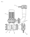
- FIG. 2 shows a view of a pump assembly with a pump 2 for a method according to the invention for emptying a service water pipe 1.
- a pre-filter 3 and the pump 2 form a structural unit.
- An injection device 8 is connected to the service water line 1 in the area between the locking slides 4, 5, wherein the injection device 8 on Prefilter 3 is arranged and is designed as a simple opening.
- An evacuation 9 is disposed between the pushers 4, 5 on the pre-filter 3, wherein it is also formed as a simple opening. Because the discharge device 9 is advantageously arranged at the lowest point of the device according to the invention, the bathwater pressed out of the prefilter 3 can drain off particularly well.
Landscapes
- Engineering & Computer Science (AREA)
- Architecture (AREA)
- Water Supply & Treatment (AREA)
- Civil Engineering (AREA)
- Structural Engineering (AREA)
- Filtration Of Liquid (AREA)
- Pipeline Systems (AREA)
- Devices For Medical Bathing And Washing (AREA)
Priority Applications (1)
| Application Number | Priority Date | Filing Date | Title |
|---|---|---|---|
| PL14152863T PL2787149T3 (pl) | 2013-04-02 | 2014-01-28 | Urządzenie do pneumatycznego opróżniania przewodu wody użytkowej |
Applications Claiming Priority (1)
| Application Number | Priority Date | Filing Date | Title |
|---|---|---|---|
| DE102013103286.9A DE102013103286A1 (de) | 2013-04-02 | 2013-04-02 | Vorrichtung zum pneumatischen Entleeren einer Brauchwasserleitung |
Publications (3)
| Publication Number | Publication Date |
|---|---|
| EP2787149A2 true EP2787149A2 (fr) | 2014-10-08 |
| EP2787149A3 EP2787149A3 (fr) | 2017-12-20 |
| EP2787149B1 EP2787149B1 (fr) | 2019-05-08 |
Family
ID=50000876
Family Applications (1)
| Application Number | Title | Priority Date | Filing Date |
|---|---|---|---|
| EP14152863.8A Active EP2787149B1 (fr) | 2013-04-02 | 2014-01-28 | Dispositif de vidange pneumatique d'une conduite d'eau |
Country Status (3)
| Country | Link |
|---|---|
| EP (1) | EP2787149B1 (fr) |
| DE (1) | DE102013103286A1 (fr) |
| PL (1) | PL2787149T3 (fr) |
Families Citing this family (1)
| Publication number | Priority date | Publication date | Assignee | Title |
|---|---|---|---|---|
| DE202021105521U1 (de) | 2021-10-12 | 2021-11-02 | Herborner Pumpentechnik Gmbh & Co Kg | Filtervorrichtung und Pumpenvorrichtung hiermit |
Family Cites Families (3)
| Publication number | Priority date | Publication date | Assignee | Title |
|---|---|---|---|---|
| US4368550A (en) * | 1981-04-10 | 1983-01-18 | Stevens Gunther A | Method and apparatus for winterizing a swimming pool |
| US5244585A (en) * | 1991-01-11 | 1993-09-14 | Akitoshi Sugimoto | Method of cleaning porous ceramic filters |
| US5577274A (en) * | 1995-05-17 | 1996-11-26 | Plotsky; David E. | Winterizing check valve system |
-
2013
- 2013-04-02 DE DE102013103286.9A patent/DE102013103286A1/de not_active Withdrawn
-
2014
- 2014-01-28 PL PL14152863T patent/PL2787149T3/pl unknown
- 2014-01-28 EP EP14152863.8A patent/EP2787149B1/fr active Active
Non-Patent Citations (1)
| Title |
|---|
| None |
Also Published As
| Publication number | Publication date |
|---|---|
| DE102013103286A1 (de) | 2014-10-02 |
| EP2787149A3 (fr) | 2017-12-20 |
| PL2787149T3 (pl) | 2019-10-31 |
| EP2787149B1 (fr) | 2019-05-08 |
Similar Documents
| Publication | Publication Date | Title |
|---|---|---|
| DE112007002409T5 (de) | Sperrventil für Vakuumabwasserrohr und Vakuumabwassersystem | |
| EP3156661B1 (fr) | Installation d'eau domestique ou pompe avec clapet anti-retour | |
| EP0527177B1 (fr) | Station d'ecouvillonnage nettoyable | |
| DE2745498C3 (de) | Vorrichtung zur Steuerung eines Nachfüllens von Flüssigkeit in eine Reinigungsmischung | |
| DE10204737A1 (de) | Verfahren und Vorrichtung zum Spülen und Reinigen einer Rohrleitung, insbesondere einer Trinkwasserleitung | |
| EP2787149B1 (fr) | Dispositif de vidange pneumatique d'une conduite d'eau | |
| DE102015107187B4 (de) | Innenraumreinigungsvorrichtung für eine Werkzeugmaschine und Reinigungsrohr, das von der Innenraumreinigungsvorrichtung für eine Werkzeugmaschine benutzt wird | |
| DE102015205825B4 (de) | Verfahren zur Frostentleerung eines Frischwasserbehälters für ein Schienenfahrzeug des Personenverkehrs und Schienenfahrzeug des Personenverkehrs mit einer Frostentleerungseinrichtung | |
| EP2786811A1 (fr) | Dispositif d'alimentation des récepteurs en liquide de nettoyage et/ou de désinfection | |
| EP2287407A2 (fr) | Dispositif de rinçage | |
| EP3020878A1 (fr) | Prise d'eau et tuyau de controle | |
| DE102014113671B4 (de) | Vorrichtung mit einem selbststeuernden Druckbehälter zur hydraulischen Entkopplung bei einem Wasserversorgungs-Direktanschluss | |
| DE1043228B (de) | Verfahren und Vorrichtung zum Ansaugen von Schlamm, insbesondere bei Schlammsaugewagen | |
| EP2921710B1 (fr) | Turbomachine avec dispositif d'étanchéité et procédures de maintenance associées | |
| EP2918738B1 (fr) | Dispositif de ventilation pour une colonne montante comprenant un dispositif de réduction de l'eau stagnante | |
| DE102012110773A1 (de) | Pumpstation und Verfahren zum Abpumpen von Abwasser | |
| EP2557069A2 (fr) | Dispositif pour une installation de préparation d'eau potable | |
| DE202011051876U1 (de) | Solardusche | |
| DE102006010569A1 (de) | Unterdruckabwassereinrichtung | |
| DE102008003274B3 (de) | Kupplungsvorrichtung | |
| DE202025107820U1 (de) | Mehrfach verwendbare Injektionsbohrnadel mit Anschlusskupplungen zum nachträglichen Abdichten von Dichtungsfugen | |
| EP3101183A1 (fr) | Système de tuyauterie avec lance d'arrosage | |
| DE102022113514A1 (de) | Spülarmatur sowie Standrohr mit einer solchen Spülarmatur | |
| DE202005009318U1 (de) | Handbetriebene Kolbensaugpumpe | |
| DE29919821U1 (de) | Versickerungsvorrichtung |
Legal Events
| Date | Code | Title | Description |
|---|---|---|---|
| PUAI | Public reference made under article 153(3) epc to a published international application that has entered the european phase |
Free format text: ORIGINAL CODE: 0009012 |
|
| 17P | Request for examination filed |
Effective date: 20140128 |
|
| AK | Designated contracting states |
Kind code of ref document: A2 Designated state(s): AL AT BE BG CH CY CZ DE DK EE ES FI FR GB GR HR HU IE IS IT LI LT LU LV MC MK MT NL NO PL PT RO RS SE SI SK SM TR |
|
| AX | Request for extension of the european patent |
Extension state: BA ME |
|
| RAP1 | Party data changed (applicant data changed or rights of an application transferred) |
Owner name: HERBORNER PUMPENTECHNIK GMBH & CO KG |
|
| PUAL | Search report despatched |
Free format text: ORIGINAL CODE: 0009013 |
|
| AK | Designated contracting states |
Kind code of ref document: A3 Designated state(s): AL AT BE BG CH CY CZ DE DK EE ES FI FR GB GR HR HU IE IS IT LI LT LU LV MC MK MT NL NO PL PT RO RS SE SI SK SM TR |
|
| AX | Request for extension of the european patent |
Extension state: BA ME |
|
| RIC1 | Information provided on ipc code assigned before grant |
Ipc: E04H 4/12 20060101AFI20171114BHEP |
|
| STAA | Information on the status of an ep patent application or granted ep patent |
Free format text: STATUS: REQUEST FOR EXAMINATION WAS MADE |
|
| R17P | Request for examination filed (corrected) |
Effective date: 20180529 |
|
| RBV | Designated contracting states (corrected) |
Designated state(s): AL AT BE BG CH CY CZ DE DK EE ES FI FR GB GR HR HU IE IS IT LI LT LU LV MC MK MT NL NO PL PT RO RS SE SI SK SM TR |
|
| GRAP | Despatch of communication of intention to grant a patent |
Free format text: ORIGINAL CODE: EPIDOSNIGR1 |
|
| STAA | Information on the status of an ep patent application or granted ep patent |
Free format text: STATUS: GRANT OF PATENT IS INTENDED |
|
| INTG | Intention to grant announced |
Effective date: 20190205 |
|
| GRAS | Grant fee paid |
Free format text: ORIGINAL CODE: EPIDOSNIGR3 |
|
| GRAA | (expected) grant |
Free format text: ORIGINAL CODE: 0009210 |
|
| STAA | Information on the status of an ep patent application or granted ep patent |
Free format text: STATUS: THE PATENT HAS BEEN GRANTED |
|
| AK | Designated contracting states |
Kind code of ref document: B1 Designated state(s): AL AT BE BG CH CY CZ DE DK EE ES FI FR GB GR HR HU IE IS IT LI LT LU LV MC MK MT NL NO PL PT RO RS SE SI SK SM TR |
|
| REG | Reference to a national code |
Ref country code: GB Ref legal event code: FG4D Free format text: NOT ENGLISH |
|
| REG | Reference to a national code |
Ref country code: CH Ref legal event code: EP Ref country code: AT Ref legal event code: REF Ref document number: 1130351 Country of ref document: AT Kind code of ref document: T Effective date: 20190515 |
|
| REG | Reference to a national code |
Ref country code: DE Ref legal event code: R096 Ref document number: 502014011630 Country of ref document: DE Ref country code: IE Ref legal event code: FG4D Free format text: LANGUAGE OF EP DOCUMENT: GERMAN |
|
| REG | Reference to a national code |
Ref country code: CH Ref legal event code: NV Representative=s name: VALIPAT S.A. C/O BOVARD SA NEUCHATEL, CH |
|
| REG | Reference to a national code |
Ref country code: NL Ref legal event code: FP |
|
| REG | Reference to a national code |
Ref country code: SE Ref legal event code: TRGR |
|
| REG | Reference to a national code |
Ref country code: NO Ref legal event code: T2 Effective date: 20190508 |
|
| REG | Reference to a national code |
Ref country code: LT Ref legal event code: MG4D |
|
| PG25 | Lapsed in a contracting state [announced via postgrant information from national office to epo] |
Ref country code: PT Free format text: LAPSE BECAUSE OF FAILURE TO SUBMIT A TRANSLATION OF THE DESCRIPTION OR TO PAY THE FEE WITHIN THE PRESCRIBED TIME-LIMIT Effective date: 20190908 Ref country code: ES Free format text: LAPSE BECAUSE OF FAILURE TO SUBMIT A TRANSLATION OF THE DESCRIPTION OR TO PAY THE FEE WITHIN THE PRESCRIBED TIME-LIMIT Effective date: 20190508 Ref country code: AL Free format text: LAPSE BECAUSE OF FAILURE TO SUBMIT A TRANSLATION OF THE DESCRIPTION OR TO PAY THE FEE WITHIN THE PRESCRIBED TIME-LIMIT Effective date: 20190508 Ref country code: HR Free format text: LAPSE BECAUSE OF FAILURE TO SUBMIT A TRANSLATION OF THE DESCRIPTION OR TO PAY THE FEE WITHIN THE PRESCRIBED TIME-LIMIT Effective date: 20190508 Ref country code: LT Free format text: LAPSE BECAUSE OF FAILURE TO SUBMIT A TRANSLATION OF THE DESCRIPTION OR TO PAY THE FEE WITHIN THE PRESCRIBED TIME-LIMIT Effective date: 20190508 |
|
| PG25 | Lapsed in a contracting state [announced via postgrant information from national office to epo] |
Ref country code: RS Free format text: LAPSE BECAUSE OF FAILURE TO SUBMIT A TRANSLATION OF THE DESCRIPTION OR TO PAY THE FEE WITHIN THE PRESCRIBED TIME-LIMIT Effective date: 20190508 Ref country code: GR Free format text: LAPSE BECAUSE OF FAILURE TO SUBMIT A TRANSLATION OF THE DESCRIPTION OR TO PAY THE FEE WITHIN THE PRESCRIBED TIME-LIMIT Effective date: 20190809 Ref country code: BG Free format text: LAPSE BECAUSE OF FAILURE TO SUBMIT A TRANSLATION OF THE DESCRIPTION OR TO PAY THE FEE WITHIN THE PRESCRIBED TIME-LIMIT Effective date: 20190808 Ref country code: LV Free format text: LAPSE BECAUSE OF FAILURE TO SUBMIT A TRANSLATION OF THE DESCRIPTION OR TO PAY THE FEE WITHIN THE PRESCRIBED TIME-LIMIT Effective date: 20190508 |
|
| PG25 | Lapsed in a contracting state [announced via postgrant information from national office to epo] |
Ref country code: CZ Free format text: LAPSE BECAUSE OF FAILURE TO SUBMIT A TRANSLATION OF THE DESCRIPTION OR TO PAY THE FEE WITHIN THE PRESCRIBED TIME-LIMIT Effective date: 20190508 Ref country code: EE Free format text: LAPSE BECAUSE OF FAILURE TO SUBMIT A TRANSLATION OF THE DESCRIPTION OR TO PAY THE FEE WITHIN THE PRESCRIBED TIME-LIMIT Effective date: 20190508 Ref country code: RO Free format text: LAPSE BECAUSE OF FAILURE TO SUBMIT A TRANSLATION OF THE DESCRIPTION OR TO PAY THE FEE WITHIN THE PRESCRIBED TIME-LIMIT Effective date: 20190508 Ref country code: DK Free format text: LAPSE BECAUSE OF FAILURE TO SUBMIT A TRANSLATION OF THE DESCRIPTION OR TO PAY THE FEE WITHIN THE PRESCRIBED TIME-LIMIT Effective date: 20190508 Ref country code: SK Free format text: LAPSE BECAUSE OF FAILURE TO SUBMIT A TRANSLATION OF THE DESCRIPTION OR TO PAY THE FEE WITHIN THE PRESCRIBED TIME-LIMIT Effective date: 20190508 |
|
| REG | Reference to a national code |
Ref country code: DE Ref legal event code: R097 Ref document number: 502014011630 Country of ref document: DE |
|
| PG25 | Lapsed in a contracting state [announced via postgrant information from national office to epo] |
Ref country code: SM Free format text: LAPSE BECAUSE OF FAILURE TO SUBMIT A TRANSLATION OF THE DESCRIPTION OR TO PAY THE FEE WITHIN THE PRESCRIBED TIME-LIMIT Effective date: 20190508 Ref country code: IT Free format text: LAPSE BECAUSE OF FAILURE TO SUBMIT A TRANSLATION OF THE DESCRIPTION OR TO PAY THE FEE WITHIN THE PRESCRIBED TIME-LIMIT Effective date: 20190508 |
|
| PLBE | No opposition filed within time limit |
Free format text: ORIGINAL CODE: 0009261 |
|
| STAA | Information on the status of an ep patent application or granted ep patent |
Free format text: STATUS: NO OPPOSITION FILED WITHIN TIME LIMIT |
|
| PG25 | Lapsed in a contracting state [announced via postgrant information from national office to epo] |
Ref country code: TR Free format text: LAPSE BECAUSE OF FAILURE TO SUBMIT A TRANSLATION OF THE DESCRIPTION OR TO PAY THE FEE WITHIN THE PRESCRIBED TIME-LIMIT Effective date: 20190508 |
|
| 26N | No opposition filed |
Effective date: 20200211 |
|
| PG25 | Lapsed in a contracting state [announced via postgrant information from national office to epo] |
Ref country code: SI Free format text: LAPSE BECAUSE OF FAILURE TO SUBMIT A TRANSLATION OF THE DESCRIPTION OR TO PAY THE FEE WITHIN THE PRESCRIBED TIME-LIMIT Effective date: 20190508 |
|
| REG | Reference to a national code |
Ref country code: DE Ref legal event code: R119 Ref document number: 502014011630 Country of ref document: DE |
|
| REG | Reference to a national code |
Ref country code: FI Ref legal event code: MAE |
|
| REG | Reference to a national code |
Ref country code: NO Ref legal event code: MMEP |
|
| PG25 | Lapsed in a contracting state [announced via postgrant information from national office to epo] |
Ref country code: MC Free format text: LAPSE BECAUSE OF FAILURE TO SUBMIT A TRANSLATION OF THE DESCRIPTION OR TO PAY THE FEE WITHIN THE PRESCRIBED TIME-LIMIT Effective date: 20190508 |
|
| REG | Reference to a national code |
Ref country code: CH Ref legal event code: PL |
|
| REG | Reference to a national code |
Ref country code: SE Ref legal event code: EUG |
|
| REG | Reference to a national code |
Ref country code: NL Ref legal event code: MM Effective date: 20200201 |
|
| GBPC | Gb: european patent ceased through non-payment of renewal fee |
Effective date: 20200128 |
|
| REG | Reference to a national code |
Ref country code: SE Ref legal event code: EUG |
|
| REG | Reference to a national code |
Ref country code: BE Ref legal event code: MM Effective date: 20200131 |
|
| PG25 | Lapsed in a contracting state [announced via postgrant information from national office to epo] |
Ref country code: FR Free format text: LAPSE BECAUSE OF NON-PAYMENT OF DUE FEES Effective date: 20200131 Ref country code: NO Free format text: LAPSE BECAUSE OF NON-PAYMENT OF DUE FEES Effective date: 20200131 Ref country code: GB Free format text: LAPSE BECAUSE OF NON-PAYMENT OF DUE FEES Effective date: 20200128 Ref country code: FI Free format text: LAPSE BECAUSE OF NON-PAYMENT OF DUE FEES Effective date: 20200128 Ref country code: SE Free format text: LAPSE BECAUSE OF NON-PAYMENT OF DUE FEES Effective date: 20200129 Ref country code: LU Free format text: LAPSE BECAUSE OF NON-PAYMENT OF DUE FEES Effective date: 20200128 Ref country code: DE Free format text: LAPSE BECAUSE OF NON-PAYMENT OF DUE FEES Effective date: 20200801 Ref country code: NL Free format text: LAPSE BECAUSE OF NON-PAYMENT OF DUE FEES Effective date: 20200201 |
|
| PG25 | Lapsed in a contracting state [announced via postgrant information from national office to epo] |
Ref country code: LI Free format text: LAPSE BECAUSE OF NON-PAYMENT OF DUE FEES Effective date: 20200131 Ref country code: CH Free format text: LAPSE BECAUSE OF NON-PAYMENT OF DUE FEES Effective date: 20200131 Ref country code: BE Free format text: LAPSE BECAUSE OF NON-PAYMENT OF DUE FEES Effective date: 20200131 |
|
| PG25 | Lapsed in a contracting state [announced via postgrant information from national office to epo] |
Ref country code: IE Free format text: LAPSE BECAUSE OF NON-PAYMENT OF DUE FEES Effective date: 20200128 |
|
| REG | Reference to a national code |
Ref country code: AT Ref legal event code: MM01 Ref document number: 1130351 Country of ref document: AT Kind code of ref document: T Effective date: 20200128 |
|
| PG25 | Lapsed in a contracting state [announced via postgrant information from national office to epo] |
Ref country code: AT Free format text: LAPSE BECAUSE OF NON-PAYMENT OF DUE FEES Effective date: 20200128 |
|
| PG25 | Lapsed in a contracting state [announced via postgrant information from national office to epo] |
Ref country code: PL Free format text: LAPSE BECAUSE OF NON-PAYMENT OF DUE FEES Effective date: 20200128 Ref country code: MT Free format text: LAPSE BECAUSE OF FAILURE TO SUBMIT A TRANSLATION OF THE DESCRIPTION OR TO PAY THE FEE WITHIN THE PRESCRIBED TIME-LIMIT Effective date: 20190508 Ref country code: CY Free format text: LAPSE BECAUSE OF FAILURE TO SUBMIT A TRANSLATION OF THE DESCRIPTION OR TO PAY THE FEE WITHIN THE PRESCRIBED TIME-LIMIT Effective date: 20190508 |
|
| PG25 | Lapsed in a contracting state [announced via postgrant information from national office to epo] |
Ref country code: MK Free format text: LAPSE BECAUSE OF FAILURE TO SUBMIT A TRANSLATION OF THE DESCRIPTION OR TO PAY THE FEE WITHIN THE PRESCRIBED TIME-LIMIT Effective date: 20190508 Ref country code: IS Free format text: LAPSE BECAUSE OF FAILURE TO SUBMIT A TRANSLATION OF THE DESCRIPTION OR TO PAY THE FEE WITHIN THE PRESCRIBED TIME-LIMIT Effective date: 20190908 |