EP2787213B1 - Pompe à carburant - Google Patents
Pompe à carburant Download PDFInfo
- Publication number
- EP2787213B1 EP2787213B1 EP14156481.5A EP14156481A EP2787213B1 EP 2787213 B1 EP2787213 B1 EP 2787213B1 EP 14156481 A EP14156481 A EP 14156481A EP 2787213 B1 EP2787213 B1 EP 2787213B1
- Authority
- EP
- European Patent Office
- Prior art keywords
- pressure
- fuel
- pump
- pressure chamber
- pressure connection
- Prior art date
- Legal status (The legal status is an assumption and is not a legal conclusion. Google has not performed a legal analysis and makes no representation as to the accuracy of the status listed.)
- Active
Links
Images
Classifications
-
- F—MECHANICAL ENGINEERING; LIGHTING; HEATING; WEAPONS; BLASTING
- F02—COMBUSTION ENGINES; HOT-GAS OR COMBUSTION-PRODUCT ENGINE PLANTS
- F02M—SUPPLYING COMBUSTION ENGINES IN GENERAL WITH COMBUSTIBLE MIXTURES OR CONSTITUENTS THEREOF
- F02M43/00—Fuel-injection apparatus operating simultaneously on two or more fuels, or on a liquid fuel and another liquid, e.g. the other liquid being an anti-knock additive
- F02M43/02—Pumps peculiar thereto
-
- F—MECHANICAL ENGINEERING; LIGHTING; HEATING; WEAPONS; BLASTING
- F02—COMBUSTION ENGINES; HOT-GAS OR COMBUSTION-PRODUCT ENGINE PLANTS
- F02M—SUPPLYING COMBUSTION ENGINES IN GENERAL WITH COMBUSTIBLE MIXTURES OR CONSTITUENTS THEREOF
- F02M25/00—Engine-pertinent apparatus for adding non-fuel substances or small quantities of secondary fuel to combustion-air, main fuel or fuel-air mixture
- F02M25/022—Adding fuel and water emulsion, water or steam
- F02M25/025—Adding water
- F02M25/028—Adding water into the charge intakes
-
- F—MECHANICAL ENGINEERING; LIGHTING; HEATING; WEAPONS; BLASTING
- F02—COMBUSTION ENGINES; HOT-GAS OR COMBUSTION-PRODUCT ENGINE PLANTS
- F02M—SUPPLYING COMBUSTION ENGINES IN GENERAL WITH COMBUSTIBLE MIXTURES OR CONSTITUENTS THEREOF
- F02M25/00—Engine-pertinent apparatus for adding non-fuel substances or small quantities of secondary fuel to combustion-air, main fuel or fuel-air mixture
- F02M25/022—Adding fuel and water emulsion, water or steam
- F02M25/025—Adding water
- F02M25/03—Adding water into the cylinder or the pre-combustion chamber
Definitions
- the invention relates to a fuel pump unit according to the preamble of claim 1.
- the combustion of the fuel in the engine can be favorably influenced if, in addition to the fuel as the first injection liquid still another, second injection liquid is provided, which is injected for example in the combustion chamber itself or in the intake manifold in front of the combustion chamber.
- second injection liquid is provided, which is injected for example in the combustion chamber itself or in the intake manifold in front of the combustion chamber.
- water is used as the second injection fluid.
- the fuel mixture and / or a reduction in the exhaust gas pollutants can be achieved by adding the second injection fluid in some characteristic map regions of the internal combustion engine.
- a fuel injection pumping apparatus in a motor vehicle including a piston pump and an additional piston such that the pumping device can simultaneously deliver two different liquid fuels to a combustion cylinder of the motor vehicle, such as high octane gasoline and diesel.
- the CA 2 758 246 discloses a method and apparatus for pumping fuel to an injection system of an internal combustion engine.
- a liquid fuel is first brought to a first pressure and then used as hydraulic fluid for driving a pump for gaseous fuel, wherein the gaseous fuel is brought by the pump to a second pressure.
- the DE 40 40 235 A1 shows an injection pump for diesel engines, in which the working space of a pump piston is limited by a coaxially arranged with the pump piston, slidably guided separating piston, wherein the separating piston through the pump piston via the in the working space of the pump piston enclosed fuel volume is hydraulically driven to move.
- the working space of the separating piston is in controlled communication with a source of at least one additional liquid, eg water, wherein a metered amount of fuel and a metered amount of water supplied to the working space and injected from the working space together in the internal combustion engine.
- the object of the invention is to provide a compact fuel pump unit, which in addition to the fuel as the first injection liquid with little design and control technology effort provides a second injection liquid for injection into a combustion chamber of the internal combustion engine.
- a fuel pump unit with the features of claim 1. This results in an advantageous manner, a "simultaneous", but materially separate promotion of the two injection fluids by means of a single pump drive.
- a delivery pressure of the fuel pump thus generates on the one hand a desired operating pressure for the fuel designated as the first injection fluid and, moreover, by means of the displacer unit also a desired operating pressure for the second injection fluid.
- the pump drive does not have to be the subject of the invention.
- an intake valve is also provided which can enable or disable a fuel line between the first low-pressure port and the pump. Because of this inlet valve can be used as a pump, a conventional fuel pump with oscillating piston, which has proven itself many times in motor vehicles.
- the displacer unit has a Verdrängerele element which separates a first pressure chamber of the displacer unit substantially liquid-tight from a second pressure chamber of the displacer unit. Consequently, the displacer generates a hydraulic coupling and at the same time a material separation of the two injection fluids with little design effort.
- the first pressure space between the first high-pressure port and the inlet valve is preferably connected to a fuel line and / or the second pressure chamber is connected to a hydraulic line for the second injection fluid.
- the pump and the displacer unit are drivingly coupled to one another via the first injection fluid, that is, the pump delivers the first injection fluid to the displacer to drive it, which in turn causes the second injection fluid to be delivered.
- the hydraulic line can connect the second low-pressure connection with the second high-pressure connection for the second injection liquid.
- the displacer unit is a cylinder / piston unit which comprises a cylinder and a piston displaceably received in the cylinder along a cylinder axis, acting as a displacer, substantially liquid-tightly dividing the cylinder into a first pressure space fillable with fuel and a second injection fluid fillable second pressure chamber.
- cylinder / piston units are due to their simple and robust design particularly reliable, durable and inexpensive, so they are particularly suitable for use in fuel pump units of internal combustion engines.
- a membrane construction would alternatively be conceivable in which a cylinder is separated into two pressure chambers by means of an elastic membrane acting as a displacement element.
- the cylinder of a displacer unit embodied as a cylinder / piston unit has a cylindrical side wall, wherein a high-pressure connection of at least one pressure chamber is formed in the side wall and is spaced from an associated axial end wall of the cylinder.
- This cylinder design causes a hydraulic stop damping for the piston, so that a low-noise operation of the fuel pump unit can be realized with little design effort.
- a spring element is provided in the first pressure chamber, which acts on the piston in the direction of the second pressure chamber.
- a spring element is also provided in the second pressure chamber, which acts on the piston in the direction of the first pressure chamber. This spring element causes a lowering of the necessary flow pressure of the second injection liquid.
- the fuel pump unit are the pump and the first pressure chamber via a fuel line hydraulically directly, that is without intermediate flow control elements, in flow communication.
- This direct flow connection allows the desired provision of an operating pressure for the second injection fluid without further control or technical control effort. Consequently, the fuel pump unit is a total of both constructive and control technology simple and inexpensive to produce.
- a valve is provided which releases a fluid flow from the second pressure chamber to the second high pressure port and blocks an opposite fluid flow
- another valve is provided, which releases a liquid flow from the second low pressure port to the second pressure chamber and blocks an opposite liquid flow.
- These valves are preferably simple check valves and ensure with little effort that the second injection liquid flows in via the second low-pressure connection and flows out via the second high-pressure connection, without there being appreciable liquid losses.
- a valve in particular a check valve is provided between the pump and the first high pressure port, which releases a flow of fuel from the pump to the first high pressure port and blocks an opposite flow of fuel.
- This valve simply and reliably prevents unwanted fuel backflow from the first high pressure port toward the pump.
- the pump may be a piston pump and the pump drive may be a cam drive.
- the pump corresponds to a currently used, proven fuel pump with conventional cam drive. Consequently The additional delivery of the second injection fluid can be integrated with little effort into already established pump systems.
- a pressure damper connected to the pump can be provided for damping pressure pulsations.
- a pressure or pulsation damper By means of such a pressure or pulsation damper, undesired, design-related delivery flow pulsations can be reduced simply and effectively to an acceptable level.
- a pressure relief valve is preferably provided between the pump and the first high pressure port.
- both the delivery pressure of the first injection fluid, i. of the fuel, as well as the delivery pressure of the second injection fluid limit to an adjustable maximum pressure, for example, to prevent damage to the fuel pump unit in case of failure of a full delivery of the pump.
- a high-pressure region for the second injection liquid is designed for the same maximum pressure as a high-pressure region for the first injection liquid. Then can be dispensed with a separate pressure relief valve to secure the high pressure area for the second injection fluid.
- a throttle valve for pressure control or pressure control of the second injection fluid is provided at the second high pressure port.
- a desired, lowered injection pressure of the second injection liquid can be easily adjusted with this throttle valve.
- the fuel as the first injection liquid differs from the second injection liquid, wherein the second injection liquid is water or a water mixture.
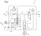
- the sole FIGURE shows a fuel pump unit 10 for injecting a fuel 12 into a combustion chamber (not shown) of an automotive internal combustion engine, with a pump 16 which can be actuated by a pump drive 14, which conveys the fuel 12 as the first injection fluid from a first low-pressure port 18 to a first high-pressure port 20.
- the fuel pump unit 10 includes an inlet valve 22 that can enable or disable a fuel line 24 between the first low pressure port 18 and the pump 16.
- a check valve designed as a valve 26 is provided between the pump 16 and the first high-pressure port 20, which releases a flow of fuel from the pump 16 to the first high pressure port 20 and blocks an opposite flow of fuel.
- a pressure damper 28 is also connected to the pump 16.
- a pressure relief valve 30 is provided between the pump 16 and the first high pressure port 20, which limits the delivery pressure of the fuel 12 to an adjustable maximum pressure.
- the pump drive 14 designed as a cam drive actuates a piston 32 of the pump 16 designed as a piston pump so that the piston 32 oscillates in a cylinder 34 of the pump 16.
- the pump 16 corresponds to a conventional fuel pump with oscillating piston 32 and conventional cam drive.
- a movement of the piston 32 downward corresponds to a so-called suction stroke of the pump 16.
- the inlet valve 22 is in the release position shown, in which the pump 16, the fuel used as the first injection fluid 12 via the first low pressure port 18 in a Working chamber 36 of the cylinder 34 can suck.
- a fluid connection to the first high pressure port 20 is blocked by the valve 26 during the suction stroke of the pump 16.
- a movement of the piston 32 upwardly corresponds to a so-called delivery stroke of the pump 16.
- the inlet valve 22 is in its closed position, so that a fluid connection to the first low pressure port 18 is blocked.
- the valve 26 allows fuel flow to the first high-pressure port 20. From this first high-pressure port 20, the fuel 12 can then be supplied via an injection device (not shown) to the combustion chamber of the motor vehicle internal combustion engine, in particular a gasoline engine.
- the delivery pressure of the fuel 12 is limited by means of the pressure limiting valve 30 to an adjustable maximum pressure.
- the peculiarity of the illustrated in the figure fuel pump unit 10 is that the pump 16 is hydraulically coupled to a displacer unit 38 and via the displacer unit 38 can promote a second injection liquid 40 from a second low pressure port 42 to a second high pressure port 44. This results in the advantage of a simultaneous, but materially separate promotion of the two injection fluids 12, 40 by means of a single pump drive 14 with minimal control effort.
- the displacer unit 38 has a displacer element 46, which separates a first pressure chamber 48 of the displacer unit 38 substantially liquid-tight from a second pressure chamber 50 of the displacer unit 38.
- a cylinder / piston unit comprising a cylinder 52 and a cylinder 52 slidably received along a cylinder axis A piston, wherein the piston forms the displacer 46 and the cylinder 52 substantially liquid-tight divided into the with fuel 12 fillable first pressure chamber 48 and the second injection liquid 40 can be filled with the second pressure chamber 50th
- the pump 16, specifically the working chamber 36 in the cylinder 34 of the pump 16, and the first pressure chamber 48 are hydraulically directly only via the fuel line 24, that is, without intermediate flow control elements, in flow communication. Due to this simple, direct pressure coupling between the pump 16 and the displacer unit 38 eliminates an intermediate, separate pressure control or pressure control for the second injection liquid 40, which brings no functional impairment with respect to the promotion of the second injection liquid 40 with it.
- the first pressure chamber 48 is connected to the fuel line 24 between the first high-pressure port 20 and the inlet valve 22, and the second pressure chamber 50 is connected to hydraulic lines 54, 55 for the second injection fluid 40, which connect the second low-pressure port 42 to the second high-pressure port 44.
- a valve designed as a check valve 56 is provided between the second high pressure port 44 and the second pressure chamber 50, which releases a liquid flow from the second pressure chamber 50 to the second high pressure port 44 and blocks an opposite liquid flow.
- another, designed as a check valve valve 58 is provided, which releases a liquid flow from the second low pressure port 42 to the second pressure chamber 50 and blocks an opposite flow of liquid.
- a delivery pressure of the second injection liquid 40 achieved as a result of the direct pressure coupling via the cylinder / piston unit formed Displacer unit 38 maximum the delivery pressure of the fuel 12 as the first injection fluid.
- a set by means of the pressure relief valve 30 maximum pressure for the fuel 12 thus also represents the maximum pressure for the second injection liquid 40, without a further, separate pressure relief for the second injection liquid 40 is necessary.
- a throttle valve 60 for pressure control or pressure regulation of the second injection fluid 40 can optionally be provided on the second high-pressure port 44.
- the throttle valve 60 is formed separately and the second high-pressure port 44 downstream.
- the throttle valve 60 is integrated into the fuel pump unit 10.
- a spring element 62 is provided in the first pressure chamber 48, which acts on the displacer 46 axially in the direction of the second pressure chamber 50.
- This spring element 62 is designed as a helical compression spring and displaces second injection fluid 40 from the second pressure chamber 50 at pump standstill. Should the second injection fluid 40 freeze due to low ambient temperatures in the range of the displacer unit 38, the displacer 46 can dodge in the direction of the first pressure chamber 48 and room for release the expansion of the second injection liquid 40. Thus, by means of the spring element 62, frost damage due to the spatial extent during freezing of the second injection liquid 40 can be avoided.
- the freeze protection can also be generated by the fact that when switching off the internal combustion engine, the fuel pressure in the pressure chamber 48 is greater than the pressure of the second injection liquid 40 in the pressure chamber 50. This displaces the displacer 46 when stopping the engine, the second injection liquid 40 from the pressure chamber 50th
- a spring element 64 is also provided in the second pressure chamber 50, which acts on the displacer 46 axially in the direction of the first pressure chamber 48.
- the spring element 64 embodied as a helical compression spring supports the fluid pressure of the second injection fluid 40 applied to the second low-pressure port 42 when the displacement element 46 is displaced in the direction of the first pressure chamber 48, whereby a required Supply pressure of the second injection liquid 40 can be lowered.
- both the spring element 62 and the spring element 64 are present and additionally bring about a mechanical stop damping of the piston 46 formed as a displacer 46 in the cylinder 52nd
- a hydraulic stop damping of the displacer element 46 via the positioning of the pressure chamber connections.
- a high pressure port 66 of the second pressure chamber 50 is formed in a side wall 68 of the cylinder 52 and spaced from an associated axial end wall 74 of the cylinder 52.
- the displacer 46 moves unattenuated to the high-pressure port 66 and then slows down its motion autonomously when it reaches the high-pressure port 66 and closes increasingly.
- the second injection liquid 40 then acts together with the hydraulic line 55 as a "hydraulic damping pad".
- a low-pressure port 72 of the second pressure chamber 50 is formed according to the figure in the end wall 74 at the associated axial end 70 of the cylinder 52, but could alternatively be provided in the side wall 68 of the cylinder 52.
- This cylinder construction causes in the second pressure chamber 50, a hydraulic stop damping for the piston, so that a low-noise operation of the fuel pump unit 10 can be realized with little design effort.
- a hydraulic stop damping may analogously also be formed on the fuel side in order to damp an end stop of the piston in the first pressure chamber 48.
- the fuel 12 differs as the first injection fluid from the second injection fluid 40, wherein the second injection fluid 40 is preferably water or a water mixture (for example, a water / alcohol mixture). It has been found that the addition of water (or a water mixture) leads to a more efficient fuel combustion in the engine and thus a reduced fuel consumption of the motor vehicle.
- the second injection fluid 40 is preferably water or a water mixture (for example, a water / alcohol mixture). It has been found that the addition of water (or a water mixture) leads to a more efficient fuel combustion in the engine and thus a reduced fuel consumption of the motor vehicle.
Landscapes
- Engineering & Computer Science (AREA)
- Chemical & Material Sciences (AREA)
- Combustion & Propulsion (AREA)
- Mechanical Engineering (AREA)
- General Engineering & Computer Science (AREA)
- Fuel-Injection Apparatus (AREA)
Claims (11)
- Unité de pompe de carburant permettant d'injecter un carburant (12) dans une chambre de combustion d'un moteur à combustion interne comprenant :une pompe (16) pouvant être actionnée par un entraînement de pompe (14) qui refoule le carburant (12) constituant un premier liquide d'injection d'un premier raccord basse pression (18) à un premier raccord haute pression (20),une chambre de travail (36) de la pompe (16) étant accouplée à une unité de refoulement, et pouvant refouler par l'intermédiaire de cette unité de refoulement (38) un second liquide d'injection (40) d'un second raccord basse pression (42) à un second raccord haute-pression (44),l'unité de refoulement (38) étant constituée par une unité cylindre / piston qui comprend un cylindre (52) ainsi qu'un piston agissant en tant qu'élément de refoulement (46) logé mobile en translation dans le cylindre (52) le long de l'axe (A) du cylindre, le piston subdivisant le cylindre (52) de façon essentiellement étanche aux liquides en une première chambre de pression (48) pouvant être remplie de carburant (12) et une seconde chambre de pression (50) pouvant être remplie par un second liquide d'injection (40),dans la seconde chambre de pression (50) étant monté un élément de ressort (64) qui rappelle le piston en direction de la première chambre de pression (48),caractérisée en ce quedans la première chambre de pression (48) il est prévu un élément de ressort (62) qui rappelle le piston en direction de la seconde chambre de pression (50),le second liquide d'injection (40) étant de l'eau ou un mélange aqueux.
- Unité de pompe de carburant conforme à la revendication 1,
caractérisée en ce qu'
il est prévu une soupape d'admission (22) pouvant permettre ou bloquer une conduite de carburant (24) située entre le premier raccord basse-pression (18) et la pompe (16). - Unité de pompe de carburant conforme à la revendication 2,
caractérisée en ce que
la première chambre de pression (48) est branchée sur la conduite de carburant (24) entre le premier raccord haute-pression (20) et la soupape d'admission (22), et/ou la seconde chambre de pression (50) est branchée sur une conduite hydraulique (54) pour le second liquide d'injection (40), et en particulier la conduite hydraulique (54) pour le second liquide d'injection (40) relie le second raccord basse pression (42) au second raccord haute pression (44). - Unité de pompe de carburant conforme à l'une des revendications précédentes,
caractérisée en ce que
le cylindre (52) comporte une paroi latérale cylindrique (68), un raccord haute-pression (66) d'au moins une chambre de pression (48, 50) étant formé dans cette paroi latérale (68) et étant situé à distance d'une paroi frontale (74) axiale associée du cylindre (52). - Unité de pompe de carburant conforme à l'une des revendications précédentes,
caractérisée en ce que
la pompe (16) et la première chambre de pression (48) sont directement en liaison fluidique par l'intermédiaire d'une conduite de carburant (24). - Unité de pompe de carburant conforme à l'une des revendications précédentes,
caractérisée en ce qu'
entre le second raccord haute-pression (44) et la seconde chambre de pression (50) il est prévu une soupape (56) qui permet la circulation de liquide de la première chambre de pression (50) vers le second raccord haute-pression (44) et bloque cette circulation en sens inverse, et en ce que entre le second raccord basse-pression (42) et la seconde chambre de pression (50) il est prévu une autre soupape (58) qui permet la circulation de liquide du second raccord basse-pression (42) vers la seconde chambre de pression (50) et bloque cette circulation en sens inverse. - Unité de pompe de carburant conforme à l'une des revendications précédentes,
caractérisée en ce que
entre la pompe (16) et le premier raccord haute-pression (20) il est prévu une soupape (26) qui permet la circulation du carburant de la pompe (16) vers le premier raccord haute-pression (20) et bloque cette circulation en sens inverse. - Unité de pompe de carburant conforme à l'une des revendications précédentes,
caractérisée en ce que
la pompe (16) est une pompe à piston et l'entraînement de pompe (14) est de préférence un entraînement à came. - Unité de pompe de carburant conforme à l'une des revendications précédentes,
caractérisée en ce qu'
il est prévu un amortisseur de pression (28) branché sur la pompe (16). - Unité de pompe de carburant conforme à l'une des revendications précédentes,
caractérisée en ce qu'
entre la pompe (16) et le premier raccord haute-pression (20) il est prévu une soupape de limitation de pression (30). - Unité de pompe de carburant conforme à l'une des revendications précédentes,
caractérisée en ce que
sur le second raccord haute-pression (44) il est prévu une soupape d'étranglement (60) pour commander ou réguler la pression du second liquide d'injection (40).
Applications Claiming Priority (1)
| Application Number | Priority Date | Filing Date | Title |
|---|---|---|---|
| DE102013205773.3A DE102013205773A1 (de) | 2013-04-02 | 2013-04-02 | Kraftstoff-Pumpeneinheit |
Publications (2)
| Publication Number | Publication Date |
|---|---|
| EP2787213A1 EP2787213A1 (fr) | 2014-10-08 |
| EP2787213B1 true EP2787213B1 (fr) | 2016-09-14 |
Family
ID=50190237
Family Applications (1)
| Application Number | Title | Priority Date | Filing Date |
|---|---|---|---|
| EP14156481.5A Active EP2787213B1 (fr) | 2013-04-02 | 2014-02-25 | Pompe à carburant |
Country Status (2)
| Country | Link |
|---|---|
| EP (1) | EP2787213B1 (fr) |
| DE (1) | DE102013205773A1 (fr) |
Cited By (1)
| Publication number | Priority date | Publication date | Assignee | Title |
|---|---|---|---|---|
| DE102019101136A1 (de) | 2019-01-17 | 2020-07-23 | Bayerische Motoren Werke Aktiengesellschaft | Brennkraftmaschine mit einer Kraftstoffeinspritzung und Verfahren zum Betreiben der Brennkraftmaschine |
Families Citing this family (1)
| Publication number | Priority date | Publication date | Assignee | Title |
|---|---|---|---|---|
| DE102018201565A1 (de) * | 2018-02-01 | 2019-08-01 | Bayerische Motoren Werke Aktiengesellschaft | Vorrichtung und Verfahren zur Zuführung von Wasser in eine Kraftstoffhochdruckpumpe einer in einem Kraftfahrzeug vorgesehenen Brennkraftmaschine |
Family Cites Families (5)
| Publication number | Priority date | Publication date | Assignee | Title |
|---|---|---|---|---|
| US3215080A (en) * | 1963-03-04 | 1965-11-02 | Bernard John Springer | Multiple delivery pump apparatus |
| DE2034816A1 (de) * | 1970-07-14 | 1972-01-20 | Audi NSU Auto Union AG, 7107 Neckars ulm | Forder und Dosierpumpe |
| DE4040235A1 (de) * | 1990-12-15 | 1992-06-17 | Bosch Gmbh Robert | Einspritzpumpe fuer dieselmotoren |
| DE602007010317D1 (de) * | 2007-11-05 | 2010-12-16 | Delphi Tech Holding Sarl | Flüssigkeitspumpen |
| CA2758246C (fr) * | 2011-11-16 | 2013-02-12 | Westport Power Inc. | Procede et appareil pour pomper du carburant dans un systeme d'injection de carburant |
-
2013
- 2013-04-02 DE DE102013205773.3A patent/DE102013205773A1/de not_active Withdrawn
-
2014
- 2014-02-25 EP EP14156481.5A patent/EP2787213B1/fr active Active
Cited By (1)
| Publication number | Priority date | Publication date | Assignee | Title |
|---|---|---|---|---|
| DE102019101136A1 (de) | 2019-01-17 | 2020-07-23 | Bayerische Motoren Werke Aktiengesellschaft | Brennkraftmaschine mit einer Kraftstoffeinspritzung und Verfahren zum Betreiben der Brennkraftmaschine |
Also Published As
| Publication number | Publication date |
|---|---|
| EP2787213A1 (fr) | 2014-10-08 |
| DE102013205773A1 (de) | 2014-10-02 |
Similar Documents
| Publication | Publication Date | Title |
|---|---|---|
| DE102004013307B4 (de) | Kraftstoffhochdruckpumpe mit einem Druckbegrenzungsventil | |
| DE112008002451B4 (de) | System und Methode zum Dosieren von Treibstoff in einem Hochdruck-Pumpensystem | |
| EP2778381B1 (fr) | Système d'injection et procédé de fonctionnement d'un système d'injection | |
| EP1141539B1 (fr) | Pompe a piston pour carburant sous haute pression | |
| DE10155247A1 (de) | Einspritzanlage mit Notlauffunktion sowie zugehöriges Notlaufverfahren | |
| EP2932086B1 (fr) | Ensemble pompe et système pour véhicule automobile | |
| EP2609332A1 (fr) | Pompe à membrane munie d'une soupape de compensation de fuite commandée par inertie | |
| EP1357283B1 (fr) | Dispositif d'injection de carburant pour un moteur à combustion interne | |
| EP1251266B1 (fr) | Dispositif de limitation de pression et système de combustible avec tel dispositif de limitation de pression | |
| DE102007000311A1 (de) | Sammlerkraftstoffeinspritzvorrichtung zum Mindern einer Überdruckbeaufschlagung eines Sammlers | |
| EP2787213B1 (fr) | Pompe à carburant | |
| EP1706287B1 (fr) | Unite d'acheminement de carburant | |
| EP3084200B1 (fr) | Dispositif d'alimentation en carburant d'un système d'injection de carburant d'un moteur à combustion interne, ainsi que soupape de décharge associée | |
| EP2659125B1 (fr) | Dispositif de regulation de pression d'un système d'injection de carburant ayant une soupape arrange du côté pression de la pompe | |
| WO2012089378A1 (fr) | Pompe d'un système d'injection de carburant | |
| DE4425339C2 (de) | Einspritzsystem | |
| DE102018202825B3 (de) | Vorrichtung und Verfahren zum Fördern von Kraftstoff und Additiv | |
| DE102012210087A1 (de) | Pumpe, insbesondere Kraftstoffhochdruckpumpe für eine Kraftstoffeinspritzeinrichtung, und Kraftstoffeinspritzeinrichtung | |
| DE102013214484A1 (de) | Kraftstoff-Pumpeneinheit | |
| DE102013212146A1 (de) | Pumpe | |
| DE102009059672B4 (de) | Brennkraftmaschine mit einem Höchstdruckeinspritzsystem und Verfahren | |
| DE10394151B4 (de) | Kraftstoff-Einspritzsystem mit einer Speicher-Füll-Ventilanordnung | |
| DE102010064179A1 (de) | Druckregelanordnung eines Kraftstoffeinspritzsystems | |
| DE10358010B3 (de) | Pumpe-Düse-Vorrichtung | |
| DE102009057927B4 (de) | Pumpe und Verfahren zur Förderung eines Fluids |
Legal Events
| Date | Code | Title | Description |
|---|---|---|---|
| PUAI | Public reference made under article 153(3) epc to a published international application that has entered the european phase |
Free format text: ORIGINAL CODE: 0009012 |
|
| 17P | Request for examination filed |
Effective date: 20140225 |
|
| AK | Designated contracting states |
Kind code of ref document: A1 Designated state(s): AL AT BE BG CH CY CZ DE DK EE ES FI FR GB GR HR HU IE IS IT LI LT LU LV MC MK MT NL NO PL PT RO RS SE SI SK SM TR |
|
| AX | Request for extension of the european patent |
Extension state: BA ME |
|
| R17P | Request for examination filed (corrected) |
Effective date: 20150224 |
|
| RBV | Designated contracting states (corrected) |
Designated state(s): AL AT BE BG CH CY CZ DE DK EE ES FI FR GB GR HR HU IE IS IT LI LT LU LV MC MK MT NL NO PL PT RO RS SE SI SK SM TR |
|
| GRAP | Despatch of communication of intention to grant a patent |
Free format text: ORIGINAL CODE: EPIDOSNIGR1 |
|
| INTG | Intention to grant announced |
Effective date: 20160518 |
|
| GRAS | Grant fee paid |
Free format text: ORIGINAL CODE: EPIDOSNIGR3 |
|
| GRAA | (expected) grant |
Free format text: ORIGINAL CODE: 0009210 |
|
| AK | Designated contracting states |
Kind code of ref document: B1 Designated state(s): AL AT BE BG CH CY CZ DE DK EE ES FI FR GB GR HR HU IE IS IT LI LT LU LV MC MK MT NL NO PL PT RO RS SE SI SK SM TR |
|
| REG | Reference to a national code |
Ref country code: GB Ref legal event code: FG4D Free format text: NOT ENGLISH |
|
| REG | Reference to a national code |
Ref country code: CH Ref legal event code: EP |
|
| REG | Reference to a national code |
Ref country code: IE Ref legal event code: FG4D Free format text: LANGUAGE OF EP DOCUMENT: GERMAN |
|
| REG | Reference to a national code |
Ref country code: AT Ref legal event code: REF Ref document number: 829287 Country of ref document: AT Kind code of ref document: T Effective date: 20161015 |
|
| REG | Reference to a national code |
Ref country code: DE Ref legal event code: R096 Ref document number: 502014001425 Country of ref document: DE |
|
| REG | Reference to a national code |
Ref country code: LT Ref legal event code: MG4D |
|
| REG | Reference to a national code |
Ref country code: NL Ref legal event code: MP Effective date: 20160914 |
|
| PG25 | Lapsed in a contracting state [announced via postgrant information from national office to epo] |
Ref country code: HR Free format text: LAPSE BECAUSE OF FAILURE TO SUBMIT A TRANSLATION OF THE DESCRIPTION OR TO PAY THE FEE WITHIN THE PRESCRIBED TIME-LIMIT Effective date: 20160914 Ref country code: RS Free format text: LAPSE BECAUSE OF FAILURE TO SUBMIT A TRANSLATION OF THE DESCRIPTION OR TO PAY THE FEE WITHIN THE PRESCRIBED TIME-LIMIT Effective date: 20160914 Ref country code: NO Free format text: LAPSE BECAUSE OF FAILURE TO SUBMIT A TRANSLATION OF THE DESCRIPTION OR TO PAY THE FEE WITHIN THE PRESCRIBED TIME-LIMIT Effective date: 20161214 Ref country code: LT Free format text: LAPSE BECAUSE OF FAILURE TO SUBMIT A TRANSLATION OF THE DESCRIPTION OR TO PAY THE FEE WITHIN THE PRESCRIBED TIME-LIMIT Effective date: 20160914 Ref country code: FI Free format text: LAPSE BECAUSE OF FAILURE TO SUBMIT A TRANSLATION OF THE DESCRIPTION OR TO PAY THE FEE WITHIN THE PRESCRIBED TIME-LIMIT Effective date: 20160914 |
|
| REG | Reference to a national code |
Ref country code: FR Ref legal event code: PLFP Year of fee payment: 4 |
|
| PG25 | Lapsed in a contracting state [announced via postgrant information from national office to epo] |
Ref country code: LV Free format text: LAPSE BECAUSE OF FAILURE TO SUBMIT A TRANSLATION OF THE DESCRIPTION OR TO PAY THE FEE WITHIN THE PRESCRIBED TIME-LIMIT Effective date: 20160914 Ref country code: GR Free format text: LAPSE BECAUSE OF FAILURE TO SUBMIT A TRANSLATION OF THE DESCRIPTION OR TO PAY THE FEE WITHIN THE PRESCRIBED TIME-LIMIT Effective date: 20161215 Ref country code: SE Free format text: LAPSE BECAUSE OF FAILURE TO SUBMIT A TRANSLATION OF THE DESCRIPTION OR TO PAY THE FEE WITHIN THE PRESCRIBED TIME-LIMIT Effective date: 20160914 Ref country code: NL Free format text: LAPSE BECAUSE OF FAILURE TO SUBMIT A TRANSLATION OF THE DESCRIPTION OR TO PAY THE FEE WITHIN THE PRESCRIBED TIME-LIMIT Effective date: 20160914 |
|
| PG25 | Lapsed in a contracting state [announced via postgrant information from national office to epo] |
Ref country code: RO Free format text: LAPSE BECAUSE OF FAILURE TO SUBMIT A TRANSLATION OF THE DESCRIPTION OR TO PAY THE FEE WITHIN THE PRESCRIBED TIME-LIMIT Effective date: 20160914 Ref country code: EE Free format text: LAPSE BECAUSE OF FAILURE TO SUBMIT A TRANSLATION OF THE DESCRIPTION OR TO PAY THE FEE WITHIN THE PRESCRIBED TIME-LIMIT Effective date: 20160914 |
|
| PG25 | Lapsed in a contracting state [announced via postgrant information from national office to epo] |
Ref country code: BG Free format text: LAPSE BECAUSE OF FAILURE TO SUBMIT A TRANSLATION OF THE DESCRIPTION OR TO PAY THE FEE WITHIN THE PRESCRIBED TIME-LIMIT Effective date: 20161214 Ref country code: SK Free format text: LAPSE BECAUSE OF FAILURE TO SUBMIT A TRANSLATION OF THE DESCRIPTION OR TO PAY THE FEE WITHIN THE PRESCRIBED TIME-LIMIT Effective date: 20160914 Ref country code: PT Free format text: LAPSE BECAUSE OF FAILURE TO SUBMIT A TRANSLATION OF THE DESCRIPTION OR TO PAY THE FEE WITHIN THE PRESCRIBED TIME-LIMIT Effective date: 20170116 Ref country code: BE Free format text: LAPSE BECAUSE OF NON-PAYMENT OF DUE FEES Effective date: 20170228 Ref country code: IS Free format text: LAPSE BECAUSE OF FAILURE TO SUBMIT A TRANSLATION OF THE DESCRIPTION OR TO PAY THE FEE WITHIN THE PRESCRIBED TIME-LIMIT Effective date: 20170114 Ref country code: CZ Free format text: LAPSE BECAUSE OF FAILURE TO SUBMIT A TRANSLATION OF THE DESCRIPTION OR TO PAY THE FEE WITHIN THE PRESCRIBED TIME-LIMIT Effective date: 20160914 Ref country code: ES Free format text: LAPSE BECAUSE OF FAILURE TO SUBMIT A TRANSLATION OF THE DESCRIPTION OR TO PAY THE FEE WITHIN THE PRESCRIBED TIME-LIMIT Effective date: 20160914 Ref country code: PL Free format text: LAPSE BECAUSE OF FAILURE TO SUBMIT A TRANSLATION OF THE DESCRIPTION OR TO PAY THE FEE WITHIN THE PRESCRIBED TIME-LIMIT Effective date: 20160914 Ref country code: SM Free format text: LAPSE BECAUSE OF FAILURE TO SUBMIT A TRANSLATION OF THE DESCRIPTION OR TO PAY THE FEE WITHIN THE PRESCRIBED TIME-LIMIT Effective date: 20160914 |
|
| REG | Reference to a national code |
Ref country code: DE Ref legal event code: R097 Ref document number: 502014001425 Country of ref document: DE |
|
| PLBE | No opposition filed within time limit |
Free format text: ORIGINAL CODE: 0009261 |
|
| STAA | Information on the status of an ep patent application or granted ep patent |
Free format text: STATUS: NO OPPOSITION FILED WITHIN TIME LIMIT |
|
| PG25 | Lapsed in a contracting state [announced via postgrant information from national office to epo] |
Ref country code: DK Free format text: LAPSE BECAUSE OF FAILURE TO SUBMIT A TRANSLATION OF THE DESCRIPTION OR TO PAY THE FEE WITHIN THE PRESCRIBED TIME-LIMIT Effective date: 20160914 |
|
| 26N | No opposition filed |
Effective date: 20170615 |
|
| PG25 | Lapsed in a contracting state [announced via postgrant information from national office to epo] |
Ref country code: MC Free format text: LAPSE BECAUSE OF FAILURE TO SUBMIT A TRANSLATION OF THE DESCRIPTION OR TO PAY THE FEE WITHIN THE PRESCRIBED TIME-LIMIT Effective date: 20160914 |
|
| REG | Reference to a national code |
Ref country code: CH Ref legal event code: PL |
|
| PG25 | Lapsed in a contracting state [announced via postgrant information from national office to epo] |
Ref country code: LI Free format text: LAPSE BECAUSE OF NON-PAYMENT OF DUE FEES Effective date: 20170228 Ref country code: CH Free format text: LAPSE BECAUSE OF NON-PAYMENT OF DUE FEES Effective date: 20170228 |
|
| REG | Reference to a national code |
Ref country code: IE Ref legal event code: MM4A |
|
| PG25 | Lapsed in a contracting state [announced via postgrant information from national office to epo] |
Ref country code: SI Free format text: LAPSE BECAUSE OF FAILURE TO SUBMIT A TRANSLATION OF THE DESCRIPTION OR TO PAY THE FEE WITHIN THE PRESCRIBED TIME-LIMIT Effective date: 20160914 |
|
| PG25 | Lapsed in a contracting state [announced via postgrant information from national office to epo] |
Ref country code: LU Free format text: LAPSE BECAUSE OF NON-PAYMENT OF DUE FEES Effective date: 20170225 |
|
| REG | Reference to a national code |
Ref country code: FR Ref legal event code: PLFP Year of fee payment: 5 Ref country code: BE Ref legal event code: MM Effective date: 20170228 |
|
| PG25 | Lapsed in a contracting state [announced via postgrant information from national office to epo] |
Ref country code: IE Free format text: LAPSE BECAUSE OF NON-PAYMENT OF DUE FEES Effective date: 20170225 |
|
| PG25 | Lapsed in a contracting state [announced via postgrant information from national office to epo] |
Ref country code: MT Free format text: LAPSE BECAUSE OF FAILURE TO SUBMIT A TRANSLATION OF THE DESCRIPTION OR TO PAY THE FEE WITHIN THE PRESCRIBED TIME-LIMIT Effective date: 20160914 |
|
| PG25 | Lapsed in a contracting state [announced via postgrant information from national office to epo] |
Ref country code: AL Free format text: LAPSE BECAUSE OF FAILURE TO SUBMIT A TRANSLATION OF THE DESCRIPTION OR TO PAY THE FEE WITHIN THE PRESCRIBED TIME-LIMIT Effective date: 20160914 |
|
| PG25 | Lapsed in a contracting state [announced via postgrant information from national office to epo] |
Ref country code: HU Free format text: LAPSE BECAUSE OF FAILURE TO SUBMIT A TRANSLATION OF THE DESCRIPTION OR TO PAY THE FEE WITHIN THE PRESCRIBED TIME-LIMIT; INVALID AB INITIO Effective date: 20140225 |
|
| PG25 | Lapsed in a contracting state [announced via postgrant information from national office to epo] |
Ref country code: CY Free format text: LAPSE BECAUSE OF FAILURE TO SUBMIT A TRANSLATION OF THE DESCRIPTION OR TO PAY THE FEE WITHIN THE PRESCRIBED TIME-LIMIT Effective date: 20160914 |
|
| PG25 | Lapsed in a contracting state [announced via postgrant information from national office to epo] |
Ref country code: MK Free format text: LAPSE BECAUSE OF FAILURE TO SUBMIT A TRANSLATION OF THE DESCRIPTION OR TO PAY THE FEE WITHIN THE PRESCRIBED TIME-LIMIT Effective date: 20160914 |
|
| PG25 | Lapsed in a contracting state [announced via postgrant information from national office to epo] |
Ref country code: TR Free format text: LAPSE BECAUSE OF FAILURE TO SUBMIT A TRANSLATION OF THE DESCRIPTION OR TO PAY THE FEE WITHIN THE PRESCRIBED TIME-LIMIT Effective date: 20160914 |
|
| REG | Reference to a national code |
Ref country code: AT Ref legal event code: MM01 Ref document number: 829287 Country of ref document: AT Kind code of ref document: T Effective date: 20190225 |
|
| PG25 | Lapsed in a contracting state [announced via postgrant information from national office to epo] |
Ref country code: AT Free format text: LAPSE BECAUSE OF NON-PAYMENT OF DUE FEES Effective date: 20190225 |
|
| P01 | Opt-out of the competence of the unified patent court (upc) registered |
Effective date: 20230502 |
|
| PGFP | Annual fee paid to national office [announced via postgrant information from national office to epo] |
Ref country code: DE Payment date: 20250210 Year of fee payment: 12 |
|
| PGFP | Annual fee paid to national office [announced via postgrant information from national office to epo] |
Ref country code: FR Payment date: 20250220 Year of fee payment: 12 |
|
| PGFP | Annual fee paid to national office [announced via postgrant information from national office to epo] |
Ref country code: IT Payment date: 20250228 Year of fee payment: 12 Ref country code: GB Payment date: 20250220 Year of fee payment: 12 |