EP2787216B1 - Filtersystem und Filteranzeigemessgerät - Google Patents
Filtersystem und Filteranzeigemessgerät Download PDFInfo
- Publication number
- EP2787216B1 EP2787216B1 EP14163017.8A EP14163017A EP2787216B1 EP 2787216 B1 EP2787216 B1 EP 2787216B1 EP 14163017 A EP14163017 A EP 14163017A EP 2787216 B1 EP2787216 B1 EP 2787216B1
- Authority
- EP
- European Patent Office
- Prior art keywords
- filter
- pressure
- compressor
- fluid
- indicator
- Prior art date
- Legal status (The legal status is an assumption and is not a legal conclusion. Google has not performed a legal analysis and makes no representation as to the accuracy of the status listed.)
- Active
Links
Images

Classifications
-
- F—MECHANICAL ENGINEERING; LIGHTING; HEATING; WEAPONS; BLASTING
- F04—POSITIVE - DISPLACEMENT MACHINES FOR LIQUIDS; PUMPS FOR LIQUIDS OR ELASTIC FLUIDS
- F04B—POSITIVE-DISPLACEMENT MACHINES FOR LIQUIDS; PUMPS
- F04B39/00—Component parts, details, or accessories, of pumps or pumping systems specially adapted for elastic fluids, not otherwise provided for in, or of interest apart from, groups F04B25/00 - F04B37/00
- F04B39/16—Filtration; Moisture separation
-
- G—PHYSICS
- G01—MEASURING; TESTING
- G01N—INVESTIGATING OR ANALYSING MATERIALS BY DETERMINING THEIR CHEMICAL OR PHYSICAL PROPERTIES
- G01N15/00—Investigating characteristics of particles; Investigating permeability, pore-volume or surface-area of porous materials
- G01N15/08—Investigating permeability, pore-volume, or surface area of porous materials
- G01N15/082—Investigating permeability by forcing a fluid through a sample
- G01N15/0826—Investigating permeability by forcing a fluid through a sample and measuring fluid flow rate, i.e. permeation rate or pressure change
-
- F—MECHANICAL ENGINEERING; LIGHTING; HEATING; WEAPONS; BLASTING
- F04—POSITIVE - DISPLACEMENT MACHINES FOR LIQUIDS; PUMPS FOR LIQUIDS OR ELASTIC FLUIDS
- F04B—POSITIVE-DISPLACEMENT MACHINES FOR LIQUIDS; PUMPS
- F04B53/00—Component parts, details or accessories not provided for in, or of interest apart from, groups F04B1/00 - F04B23/00 or F04B39/00 - F04B47/00
- F04B53/20—Filtering
-
- G—PHYSICS
- G01—MEASURING; TESTING
- G01N—INVESTIGATING OR ANALYSING MATERIALS BY DETERMINING THEIR CHEMICAL OR PHYSICAL PROPERTIES
- G01N15/00—Investigating characteristics of particles; Investigating permeability, pore-volume or surface-area of porous materials
- G01N15/08—Investigating permeability, pore-volume, or surface area of porous materials
- G01N2015/084—Testing filters
Definitions
- the present disclosure generally relates to gauges used with systems having filters, and more particularly, but not exclusively, to gauges that display parameters relating to compressor system operation.
- One embodiment of the present disclosure includes a unique system having a compressor, a filter and a gauge operative to simultaneously indicate at least two different parameters with a unitary movable indicator.
- Other embodiments include apparatuses, systems, devices, hardware, methods, and combinations for indicating system performance, e.g., including compressor performance. Further embodiments, forms, features, aspects, benefits, and advantages of the present application shall become apparent from the description and figures provided herewith.
- system 1000 is configured to filter and compress air. In other embodiments, system 1000 may be configured to only compress air, only filter air, or filter and/or compress air in addition to performing other functions.
- system 1000 includes a multiple indicator gauge 100, a compressor 200, and a filter 300. Gauge 100 is in fluid communication with filter 300, and filter 300 is in fluid communication with compressor 200. In some embodiments, such as that illustrated in FIG. 1 , gauge 100 may also be considered to be in fluid communication with compressor 200. In one form, the general course of airflow is in direction 140, whereby filter 300 is disposed and structured to filter air that is supplied to compressor 200.
- the general course of air flow may be in direction 142, whereby filter 300 is disposed and structured to filter air that is discharged from compressor 200.
- gauge 100 is configured to detect the pressure drop across filter 300, and to display one or more parameters as set forth herein.
- air is supplied to filter 300 by a line 150, and air is discharged from filter 300 via a line 152 and supplied to compressor 200.
- Compressor 200 discharges the compressed air via discharge line 154.
- Multiple indicator gauge 100 is in fluid communication with line 150 on a filter input side or high pressure side via a high pressure line 120A.
- Multiple indicator gauge 100 is in fluid communication with line 152 on a filter discharge side or low pressure side via a low pressure line 120A.
- lines 150, 152 and 154 are pressurized air lines, e.g., which may take the form of tubing, piping, hosing, and/or internal passages in one or more components, such as filter 300 and/or compressor 200.
- lines 120A and 120B are air pressure lines, which may also take the form of tubing, piping, hosing, and/or internal passages in one or more components, such as filter 300 and/or compressor 200.
- air is supplied to system 1000 via line 150.
- compressor 200 is configured to compress air that is received through line 152 after the air has passed through filter 300, but it will be appreciated that in other embodiments the relative placement of the components can be rearranged or different than that depicted and described herein.
- compressor 200 may be referred to compressing air, it will be appreciated that the compressor 200 can be used to compress many different types of compressible fluids other than air.
- filter 300 increasingly collects contaminants from the air entering therein via line 150. As the amount of collected contaminants increases, the pressure drop across filter 300 correspondingly increases, whereby the static pressure measured upstream of filter 300, e.g., in line 150, will be increasingly higher than the static pressure measured at a location downstream of filter 300, e.g., in line 152.
- Compressor 200 is a powered mechanical compressor, such as, but not limited to, a scroll pump, used to compress a gas.
- the reference numeral 200 also includes one or both of a motor (e.g. an electric motor or an engine) used to drive the compressor, as well as a tank used to receive and store the compressed gas.
- a motor e.g. an electric motor or an engine
- the compressed gas can be used for any type of end user such as, but not limited to, pneumatic powered tools, facility air, etc.
- Filter 300 in the depicted embodiment is in fluid communication with pressure line 152, and is configured to trap contaminants present in the gas to be compressed by compressor 200.
- filter 300 is configured to capture particulate matter.
- filter 300 may be configured to capture liquids, such as water, oil and/or fuel.
- filter 300 may take on any variety of forms and can include one or multiple separate filtering elements suitable for the particular application.
- the filter may be constructed of paper and/or fiber media, among potential others, and may be configured to be readily replaceable and/or rechargeable. As discussed above, the filter will impose an increasing pressure loss in the fluid as the filter collects increasing amounts of contaminants. This pressure loss can be detected by sampling pressure in the gas at different stream locations.
- upstream and downstream pressures are measured are depicted in the illustrated embodiment as being placed a distance away from the filter 300, but other embodiments can include pressures measured at one or more different locations.
- the upstream pressure can be sampled on the immediate upstream face of the filter 300, internal or external to filter 300 and/or the downstream pressure can be sampled on the immediate downstream face of the filter 300, internal or external to filter 300.
- one or both of the upstream and downstream locations can be within a portion of the filter 300.
- line 152 and filter 300 may be integrated together with the compressor 200, e.g., in an integrated or standalone unit, although many other variations are contemplated.
- Gauge 100 is structured to react to the pressure drop caused by the filter, and in the illustrated embodiment the downstream pressure tap is coupled directly to the compressor line 152.
- the upstream side to which the gauge 100 pressure tap is coupled can be a line similar to compressor line 152.
- gauge 100 is in communication with a high pressure side of filter 300 via high pressure tap or tube 120A, and is in communication with a low pressure side of filter 300 via low pressure tap or tube 120B.
- gauge 100 is a differential pressure sensor configured to sense and indicate a pressure loss across filter 300.
- Gauge 100 may be configured to react and indicate the differential pressure using any number of techniques.
- the gauge 100 includes a diaphragm or alternatively a bourdon tube that displaces when exposed to pressure, e.g., to differential pressure, and the displacement is used to drive the movement of an indicator related to the gauge 100.
- Other additional and/or alternative manners of detecting differential pressure are contemplated.
- gauge 100 can include a solid state piezoresistive silicon differential pressure sensor, a capacitive sensor, a bonded strain gauge sensor, a bonded foil gauge sensor, a diaphragm sensor, or a microelectromechanical systems (MEMS) sensor.
- the differential pressure sensor may set the position of needle 112 (described in detail below) directly, as would be the case with a bourdon-type differential pressure sensor.
- gauge 100 may include a controller (not shown) configured to command the needle to a given position based upon information received from the differential pressure sensor. It will be understood that gauge 100 may take one or more of various forms, and may be configured to measure the pressure drop across filter 300, e.g., as a differential pressure, using any number of techniques.
- lines 120A and 120B are a high pressure tube and a low pressure tube, respectively.
- lines 120A and 120B may be a means to convey a signal of a measurement while the measurement is conducted elsewhere, e.g., wired, wireless or optical communication links configured to send pressure signals from the sensor locations to gauge 100.
- the measurement may be taken by a pressure sensor while the gauge both interprets and indicates the value of that measured data.
- the data measured by the pressure sensor may be interpreted elsewhere, such as by a microprocessor, and the gauge merely indicates the differential pressure or information derived from and/or used in the determination of differential pressure.
- Gauge 100 includes a gauge face 102 having a plurality of indicator scales 104A and 104B.
- Scales 104A and 104B may be labeled such that each delineates a range of one or more properties, each in different units, whether the properties are measured or derived properties.
- scale 104A may be labeled in metric units
- scale 104B may be labeled in English units.
- scales 104A and 104B may be labeled such that each delineates a range of a different, but related, property.
- scale 104A may indicate the differential pressure across filter 300, while scale 104B indicates a system efficiency.
- scale 104A is a differential pressure, e.g., the pressure drop across filter 300.
- scale 104A may be related to a static pressure, e.g., in line 152 or line 150.
- a greater differential pressure across filter 300 indicates greater blockage of the filter, and hence a lower system 1000 efficiency.
- the impact/costs of operating the compressor 200 with a dirty filter may be expressed as some type of measure of system efficiency, and in general will be understood to relate to an economic loss associated with operating the compressor 200 with a dirty filter.
- the measure of system efficiency may be a monetary cost required to operate the compressor 200.
- scale 104B may be labeled to indicate the cost efficiency of the filter in terms of monetary unit/volume/time, such as dollars/m 3 /hr.
- the cost may be an incremental cost in operating the compressor 200, and in some forms the cost may be representative of a total cost in operating the compressor.
- scale 104B may represent an estimate of lost productivity.
- impact/cost displayed by the gauge 100 via scale 104B may be represented in various embodiments by quantitative and/or qualitative measures.
- Scales 104A, 104B may be indicated or differentiated by the use of different colors, color intensities or the like, and/or by different hatching and/or numerical data.
- the gradations are illustrated as sections or zones 106A, 106B, 108A, 108B, 110A, 110B are indicative of various operating conditions.
- scales 104A, 104B may be divided into three sections or zones 106A, 106B, 108A, 108B, 110A, 110B. In other embodiments, any number of gradations or sections or zones may be employed.
- the gradations pertain to, for example, a normal operating zone 106A, 106B; a marginal operating zone 108A, 108B; and a critical operating zone 110A, 110B.
- filter 300 may be replaced and/or regenerated at any time, and hence the terms “marginal” or “critical” are meant in a relative sense only. In some applications, however, the terms “marginal” or “critical” can mean that system 1000, e.g., compressor 200 performance, life and/or operability are being or may be detrimentally impacted by continued operation, for example, in terms of providing compressed fluids for an end user.
- scales 104A, 104B represent an arc segment about the axis of rotation 118 (discussed in detail below) but other shapes are contemplated for the various embodiments of scales discussed herein.
- scales 104A and 104B are printed or otherwise fixedly mounted to gauge face 102.
- one or more of scales 104A and 104B is removable and replaceable, such that the ranges can be altered so as to compensate for changes in or modifications to system 1000.
- one or more of scales 104A and 104B may be an electronic display, for example, including a plurality of light-emitting diodes. In such embodiments, the electronic display may be set by a controller or user interface (not shown).
- the scales can be moveable and the needle, or other similar indication, can be fixed. The variations associated with the embodiment depicted in FIG. 2 are also contemplated as being applicable to other embodiments of the gauge.
- an indicator needle 112 is provided with first and second indicating ends 114A, 114B.
- the number of indicating ends, e.g., 114A, 114B is equal to the number of scales, e.g., 104A, 104B on the dial face 102.
- the needle 112 is pivotably or rotatably mounted to the gauge 100 via a post 116, and pivots or rotates in response to the property being measured.
- the post 116 extends from a back surface of the indicator needle that faces the dial face 102 and extends through the dial face 102 into the inner mechanism of the gauge 100.
- the post 116 has an axis of rotation 118 about which the indicator needle 112 pivots or rotates.
- the axis of rotation acts as a common pivot point about which each indicating end 114A, 114B pivots or rotates.
- Each indicating end 114A, 114B is associated with a particular scale 104A, 104B. As shown, the first indicating end 114A is associated with the first scale 104A, and the second indicating end 114B is associated with the second scale 104B.
- Indicating ends 114A, 114B may overlap their associated scales 104A, 104B, e.g., radially, or otherwise point to a location on respective scales 104A, 104B so that a user can observe and determine the value of the measured property.
- indicating ends 114A, 114B are generally limited in motion to the arc segment that its associated scale 104A, 104B represents. In other words, a particular indicating end 114A, 114B is generally limited to only being able to point to a location within its associated scale 104A, 104B. Because the illustrated embodiment has two scales in discrete locations, the needle 112 will generally not be capable of making a full rotation. It is appreciated, however, that other configurations may make this possible should the two scales 104A, 104B overlap one another.
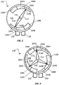
- a multiple indicator gauge 200 for indicating a range of one or more values of a property.
- the gauge 200 is provided with a dial or dial face 202 that has a first indicator scale 204A thereon.
- a second indicator scale 204B is also provided on the dial face 202.
- a third indicator scale 204C is provided on the dial face 202.
- Scales 204A, 204B, 204C may include labels to delineate ranges of one or more properties, including measured or derived properties, in one or more units.
- gauge 200 is configured to sense and indicate a differential pressure.
- scale 204A is labeled with metric units
- scale 204B is labeled with English units
- scale 204C is labeled with a system efficiency.
- Scales 204A, 204B, 204C include gradations that may be in the form of colored, or otherwise delineated, sections or zones 206A, 206B, 206C, 208A, 208B, 208C, 210A, 210B, 210C indicating various operating conditions or parameters.
- the scales 204A, 204B, 204C may be divided into three sections or zones 206A, 206B, 206C, 208A, 208B, 208C, 210A, 210B, 210C such as, for example, a normal operating zone 206A, 206B, 206C; a marginal operating zone 208A, 208B, 208C; and a critical operating zone 210A, 210B, 210C.
- scales 204A, 204B, 204C may be divided into any number of gradations, sections or zones, greater or lesser in number.
- the scales 204A, 204B, 204C represent an arc segment about the axis of rotation 218 (discussed in detail below).
- a unitary movable indicator in the form of indicator needle 212 is provided with a first, second, and third indicating ends 214A, 214B, 214C.
- the number of indicating ends 214A, 214B, 214C is equal to the number of scales 204A, 204B, 204C on the dial face 202.
- Needle 212 is rotatably mounted to the gauge 200 via a post 216, and pivots or rotates in response to the property being measured.
- Post 216 extends from a back surface of the indicator needle that faces the dial face 202, and extends through the dial face 202 into the inner mechanism of the gauge 200.
- Post 216 has an axis of rotation 218 about which the indicator needle 212 pivots or rotates.
- Axis of rotation 218 acts as a common pivot point about which each indicating end 214A, 214B, 214C pivots or rotates.
- Each indicating end 214A, 214B, 214C is associated with a particular scale 204A, 204B, 204C.
- the first indicating end 214A is associated with the first scale 204A
- the second indicating end 214B is associated with the second scale 204B
- the third indicating end 214C is associated with the third scale 204C.
- An indicating end 214A, 214B, 214C may overlap its associated scale 204A, 204B, 204C or otherwise point to a location on the scale 204A, 204B, 204C so that a user can determine the value of the measured property.
- indicating ends 214A, 214B, 214C rotate and are displaced along the arcs represented by associated scales 204A, 204B, 204C.
- the rotation of needle 212 and the rotational or circumferential displacement of indicating ends 214A, 214B, 214C are generally limited to the arc segments associated with scales 204A, 204B, 204C. That is, a particular indicating end 214A, 214B, 214C is generally limited to pointing to a location within its associated scale 204A, 204B, 204C.
- the needle 212 of that embodiment will generally not be capable of making a full rotation. It will be understood, however, that other configurations may make greater degrees of rotation possible, for example, wherein scales 204A, 204B, 204C overlap one another.
- gauge 200 has three indicating ends and associated scales, it will be understood that greater or lesser numbers of indicating ends and associated scales may be provided.
- the gauge 200 may further be provided with one or more input ports 220 similar to those discussed above with respect to FIG. 2 .
- the scales 104A, 104B are depicted on opposite sides of the dial face 102 and the indicating ends 114A, 114B extend from the post 116 at an angle of 180° from each other.
- the scales 104A, 104B may be in other locations, and the indicating ends 114A, 114B may extend from the post 116 at a relative angle less than 180° with respect to each other.
- the indicator needle 212 has three indicating ends 214A, 214B, 214C that extend from the post at a relative angle of 120° with respect to their adjacent indicating end 214A, 214B, 214C.
- the scales 104A, 104B, 204A, 204B, 204C may correlate to one another and may be proportional to one another with a 1:1 ratio or any other proportional relationship.
- the gauge 100, 200 may be configured to measure and/or indicate any number of a variety of values that are measured and/or derived, e.g., associated with filter 300, such as the pressure drop across filter 300.
- the gauge 100, 200 can be configured to indicate a pressure; a temperature; a voltage (e.g.
- the first scale 104A of the gauge 100 in FIGS. 1 and 2 may be used to indicate a pressure differential across the air filter 300, while the second scale 104B indicates a cost efficiency for running the compressor 200, it being understood that the greater the degree of blockage of filter 300, the corresponding greater cost to operate compressor 200.
- the first scale 104A may indicate the pressure differential in bar and also be divided into zones 106A, 108A, 110A representing: normal operation 106A, such as the filter 300 is working properly; marginal operation 108A, such as the filter 300 will need to be changed or cleaned soon; and a critical operating condition 110A that may indicate a condition that needs to be addressed, such as the filter 300 needs to be changed or cleaned.
- the second scale 104B may indicate the cost efficiency of the filter in terms of monetary unit/volume/time, such as dollars/m 3 /hour, and may also be divided into zones 106B, 108B, 110B, for example, with 106B representing normal operation, 108B representing marginal operation, and 110B representing a critical operating condition that may indicate a situation or occurrence that needs to be addressed.
- the zones may be color coded, such as, for example, wherein the normal operation zones 106A, 106B may be green, the marginal operation zones 108A, 108B may be yellow, and the critical operating condition zones 110A, 110B may be red.
- a pressure differential scale that uses colors such as red, yellow, and green can represent, for example, that: the filter element needs to be changed, the filter element should preferably be changed within some number of operating hours, and the filter element condition is nominal and acceptable for continued operation until gauge 100 indicates otherwise, respectively.
- an economic scale that uses colors such as red, yellow, and green can represent that the running cost is normal, that the running cost is increasing, and that the running cost is high, respectively.
- Embodiments of the present invention include an apparatus, comprising: an air compressor; a filter in fluid communication with the air compressor; the filter being structured to capture contaminants from air received therein and to provide filtered air, the filter having a pressure drop associated therewith that increases in relation to the amount of captured contaminants; an indicator gauge in fluid communication with the filter, the indicator gauge including a unitary movable indicator operative to move in relation to the pressure drop across the filter, wherein the unitary movable indicator is structured to provide a first visible indication related to a pressure and simultaneously provide a second visible indication related to an economic parameter associated with operating the air compressor while the filter is in the state of having accumulated the amount of captured contaminants corresponding to the pressure drop.
- the filter is located upstream of the compressor and is configured to supply filtered air to the air compressor.
- the filter is located downstream of the compressor and is structured to filter air discharged from the air compressor.
- the unitary movable indicator is a pivotable needle having a first end and a second end; the first end provides the indication relating to pressure; and the second end provides the indication relating to the economic parameter.
- the apparatus further comprises a first pressure tap and a second pressure tap, wherein the first pressure tap communicates a pressure upstream of the filter to the indicator gauge; and wherein the second pressure tap communicates a pressure downstream of the filter to the indicator gauge.
- the indicator gauge includes a first static color coded scale indicating a plurality of degrees of contamination of the filter, and wherein the unitary movable indicator includes a first end paired with the first static color coded scale.
- the indicator gauge includes a second static color coded scale indicating a plurality of degrees of the economic parameter, and wherein the unitary movable indicator includes a second end paired with the second static color coded scale.
- Embodiments of the present invention include an apparatus, comprising: a fluid intake line operative to supply a fluid; a filtered fluid line; a filter having an inlet in fluid communication with the fluid intake line and an exit in fluid communication with the filtered fluid line; the filter being structured to capture contaminants from the supplied fluid to generate filtered fluid, and to deliver the filtered fluid to the filtered fluid line; the filter having a pressure drop associated therewith that increases in relation to the amount of captured contaminants; a compressor in fluid communication with the filtered fluid line and operative to receive filtered fluid from the filter and compress the received filtered fluid; and an indicator gauge in fluid communication with the filter inlet and the filter exit, the indicator gauge being structured to react to a pressure drop across the filter during operation of the compressor, wherein the indicator gauge includes a unitary movable indicator operative to move in relation to the pressure drop and to display both a first indication related to a pressure in at least one of the fluid intake line and the filtered fluid line, and also display a second indication related to an economic cost associated with operating the compressor
- the pressure indicated by the indicator gauge is a differential pressure associated with filter, the differential pressure being determined by a pressure upstream of the filter and a pressure downstream of the filter.
- the unitary movable indicator is a pivoting needle.
- the pivoting needle includes a pivot point and at least two ends extending from the pivot point, wherein one end indicates a pressure of the fluid and the other end indicates an economic impact.
- the pivoting needle includes only two ends on opposite sides of the pivot point.
- the economic cost is a monetary scale that indicates a range between a relatively low monetary impact and a relatively high monetary impact.
- the compressor includes a motor driving a compression member and a fluid tank that receives the compressed fluid.
- Embodiments of the present invention include a method, comprising: powering a compressor to pressurize a fluid; flowing fluid through a filter to remove contaminants; sensing a pressure drop across the filter; moving an indicator and a scale relative to each other in response to the pressure drop; and displaying a fluid pressure parameter and a monetary cost of the powering as a result of the moving.
- the displaying includes sweeping the indicator past a scale having a low side and a high side.
- the displaying includes sweeping a first end of the indicator past a first scale and sweeping a second end of the indicator past a second scale.
- the displaying includes color coding at least one of the pressure parameter and the monetary cost.
- the method further includes storing the pressurized fluid in a tank.
- the method further includes mechanically compressing the fluid, and wherein the flowing of the fluid through the filter occurs upstream of the mechanically compressing.
Landscapes
- Engineering & Computer Science (AREA)
- Mechanical Engineering (AREA)
- General Engineering & Computer Science (AREA)
- Chemical & Material Sciences (AREA)
- Physics & Mathematics (AREA)
- Life Sciences & Earth Sciences (AREA)
- Dispersion Chemistry (AREA)
- Health & Medical Sciences (AREA)
- Fluid Mechanics (AREA)
- Analytical Chemistry (AREA)
- Biochemistry (AREA)
- General Health & Medical Sciences (AREA)
- General Physics & Mathematics (AREA)
- Immunology (AREA)
- Pathology (AREA)
- Compressor (AREA)
- Filtering Of Dispersed Particles In Gases (AREA)
Claims (13)
- Eine Vorrichtung (1000), umfassend:einen Kompressor (200);einen Filter (300) in Fluidverbindung mit dem Kompressor (200); wobei der Filter (300) so aufgebaut ist, dass er Verunreinigungen aus einem darin aufgenommenen Fluid erfasst und ein gefiltertes Fluid liefert, wobei der Filter (300) einen damit verbundenen Druckabfall aufweist, der mit der Menge an erfassten Verunreinigungen zunimmt; undein Anzeigeinstrument (100), das mit dem Filter (300) in Fluidverbindung steht, wobei das Anzeigeinstrument (100) einen mittig gelagerten Zeiger aufweist, der sich entsprechend dem Druckabfall am Filter (300) bewegt;dadurch gekennzeichnet ist, dass der mittig gelagerte Zeiger so aufgebaut ist, dass er eine erste sichtbare Anzeige liefert, die sich auf den Druck bezieht und gleichzeitig eine zweite sichtbare Anzeige liefert, die sich auf einen mit dem Betrieb des Kompressors (200) verbundenen wirtschaftlichen Parameter bezieht, wenn der Filter (300) entsprechend dem Druckabfall eine gewisse Menge an Verunreinigungen angesammelt hat.
- Die Vorrichtung gemäß Anspruch 1, wobei der Filter (300) vor dem Kompressor (200) angeordnet ist und so ausgelegt ist, dass er dem Kompressor (200) gefiltertes Fluid zuführt.
- Die Vorrichtung gemäß Anspruch 1, wobei der Filter (300) nach dem Kompressor (200) angeordnet ist und so ausgelegt ist, dass er vom Kompressor (200) abgegebenes Fluid filtert.
- Die Vorrichtung gemäß Anspruch 1, wobei der mittig gelagerte Zeiger eine drehbare Nadel (112; 212) mit einem ersten Ende (114A; 214A) und einem zweiten Ende (114B; 214B) ist; wobei das erste Ende (114A; 214A) die Anzeige bezüglich des Drucks liefert; und wobei das zweite Ende (114B; 214B) die Anzeige bezüglich des wirtschaftlichen Parameters liefert.
- Die Vorrichtung gemäß Anspruch 1, ferner umfassend eine erste Druckmessstelle (120A) und eine zweite Druckmessstelle (120B), wobei die erste Druckmessstelle (120A) den Druck vor dem Filter (300) an das Anzeigeinstrument (100) kommuniziert; und wobei die zweite Druckmessstelle (120B) den Druck nach dem Filter (300) an das Anzeigeinstrument (100) kommuniziert.
- Die Vorrichtung gemäß Anspruch 1, wobei das Anzeigeinstrument (100) eine erste statische farbkodierte Skala (104A; 204A) aufweist, die eine Vielzahl von Verschmutzungsgraden des Filters (300) anzeigt und wobei der mittig gelagerte Zeiger ein erstes Ende (114A; 214A) aufweist, das mit der ersten statischen farbkodierten Skala (104A; 204A) gepaart ist.
- Die Vorrichtung gemäß Anspruch 6, wobei das Anzeigeinstrument (100) eine zweite statische farbkodierte Skala (104B; 204B) aufweist, die eine Vielzahl von Graden des wirtschaftlichen Parameters anzeigt und wobei der mittig gelagerte Zeiger ein zweites Ende (114B; 214B) aufweist, das mit der zweiten statischen farbkodierten Skala (104B; 204B) gepaart ist.
- Die Vorrichtung gemäß einem der Ansprüche 1 bis 7, ferner umfassend:eine Fluideinlassleitung (150), die ein Fluid zuführt;eine gefilterte Fluidleitung (152); wobeider Filter (300) einen Einlass aufweist, der mit der Fluideinlassleitung (150) in Fluidverbindung steht und einen Auslass aufweist, der mit der gefilterten Fluidleitung (152) in Fluidverbindung steht und so ausgelegt ist, dass er das gefilterte Fluid der gefilterten Fluidleitung (152) zuführt, wobei der Kompressor (200) mit der gefilterten Fluidleitung (152) in Fluidverbindung steht und dazu dient, gefiltertes Fluid aus dem Filter (300) zu empfangen und das empfangene gefilterte Fluid zu komprimieren; wobeidas Anzeigeinstrument (100) mit dem Filtereinlass und dem Filterauslass in Fluidverbindung steht und so aufgebaut ist, dass es beim Betrieb des Kompressors (200) auf einen Druckabfall am Filter (200) reagiert; und wobei sich der mittig gelagerte Zeiger entsprechend dem Druckabfall bewegt und sowohl eine erste Anzeige in Bezug auf den Druck in mindestens der Fluideinlassleitung (150) und der gefilterten Fluidleitung (152) liefert als auch eine zweite Anzeige, die sich auf die wirtschaftlichen Kosten bezieht, die mit dem Betrieb des Kompressors (200) mit dem Filter (300) verbunden sind, wenn er entsprechend dem Druckabfall eine bestimmte Menge an Verunreinigungen angesammelt hat.
- Die Vorrichtung gemäß Anspruch 8, wobei der durch das Anzeigeinstrument (100) angezeigte Druck ein mit dem Filter (300) verbundener Differenzdruck ist, wobei der Differenzdruck durch einen Druck vor dem Filter (300) und einen Druck nach dem Filter (300) bestimmt wird.
- Ein Verfahren, umfassend:einen Kompressor (200) antreiben, um ein Fluid unter Druck zu setzen;ein Fluid durch einen Filter (300) strömen lassen, um Verunreinigungen zu entfernen;einen Druckabfall am Filter (300) erfassen; undals Reaktion auf einen Druckabfall einen Zeiger und eine Skala relativ zueinander bewegen,und dadurch gekennzeichnet ist, dass durch diese Bewegung ein Fluiddruckparameter und die monetären Kosten des Antriebs angezeigt werden.
- Das Verfahren gemäß Anspruch 10,
wobei das Anzeigen umfasst, den Zeiger über eine Skala (104A, 104B; 204A, 204B, 204C) mit einer niedrigen Seite und einer hohen Seite zu führen. - Das Verfahren gemäß Anspruch 10,
wobei das Anzeigen umfasst, ein erstes Ende (114A; 214A) des Zeigers über eine erste Skala (104A; 204A) und ein zweites Ende (114B; 214B) des Zeigers über eine zweite Skala (104B; 204B) zu führen. - Das Verfahren gemäß Anspruch 10,
wobei die Anzeige die Farbkodierung von mindestens dem Druckparameter und den monetären Kosten umfasst.
Applications Claiming Priority (1)
| Application Number | Priority Date | Filing Date | Title |
|---|---|---|---|
| US201361807275P | 2013-04-01 | 2013-04-01 |
Publications (2)
| Publication Number | Publication Date |
|---|---|
| EP2787216A1 EP2787216A1 (de) | 2014-10-08 |
| EP2787216B1 true EP2787216B1 (de) | 2017-07-26 |
Family
ID=50434020
Family Applications (1)
| Application Number | Title | Priority Date | Filing Date |
|---|---|---|---|
| EP14163017.8A Active EP2787216B1 (de) | 2013-04-01 | 2014-04-01 | Filtersystem und Filteranzeigemessgerät |
Country Status (2)
| Country | Link |
|---|---|
| US (1) | US20140290559A1 (de) |
| EP (1) | EP2787216B1 (de) |
Families Citing this family (6)
| Publication number | Priority date | Publication date | Assignee | Title |
|---|---|---|---|---|
| US10434453B2 (en) | 2014-12-31 | 2019-10-08 | Ingersoll-Rand Company | Compressor system having filter assembly with replaceable filter element holder |
| CN105927529A (zh) * | 2016-06-14 | 2016-09-07 | 中广核工程有限公司 | 核级泵入口滤网监测装置 |
| EP3684492A4 (de) * | 2017-09-18 | 2021-06-02 | Evoqua Water Technologies LLC | Led-statuslicht für sandfilter |
| US12044423B2 (en) | 2020-01-07 | 2024-07-23 | Stmicroelectronics S.R.L. | Device and method for monitoring HVAC air filter |
| US20220397465A1 (en) * | 2021-06-10 | 2022-12-15 | Vis, Llc | Pressure gauge portable ram kit |
| USD1070924S1 (en) | 2021-06-10 | 2025-04-15 | Kku/Iss, Inc. | Portable pump with a multiple register pressure gauge |
Family Cites Families (13)
| Publication number | Priority date | Publication date | Assignee | Title |
|---|---|---|---|---|
| US367863A (en) * | 1887-08-09 | Thermometer-scale | ||
| US2924022A (en) * | 1960-02-09 | Rotary indicators | ||
| US2638866A (en) * | 1950-06-13 | 1953-05-19 | Luther W Sage | Combination pressure and cost computing gauge attachment |
| US5033271A (en) * | 1987-11-04 | 1991-07-23 | Kent-Moore Corporation | Refrigerant recovery and purification system |
| US5327741A (en) * | 1990-10-12 | 1994-07-12 | Envirotech Systems | Refrigerant recovery and purification machine |
| WO1992016801A1 (en) * | 1991-03-22 | 1992-10-01 | Environmental Products Amalgamated Pty. Ltd. | Apparatus for servicing refrigeration systems |
| US5222369A (en) * | 1991-12-31 | 1993-06-29 | K-Whit Tools, Inc. | Refrigerant recovery device with vacuum operated check valve |
| US5272882A (en) * | 1992-01-03 | 1993-12-28 | American Standard Inc. | Portable recycle/recovery/charging system with reconfigurable components |
| US5711787A (en) * | 1995-11-22 | 1998-01-27 | Praxair Technology, Inc. | Oxygen recovery pressure swing adsorption process |
| US6190442B1 (en) * | 1999-08-31 | 2001-02-20 | Tishken Products Co. | Air filter gauge |
| GB2402736B (en) * | 2003-06-13 | 2007-04-11 | Aircontrol Technologies Ltd | Air environment control system |
| US8156997B1 (en) * | 2005-01-15 | 2012-04-17 | TMS Company LLC | Heated and cooled compressed air device and method |
| US8623117B2 (en) * | 2011-06-20 | 2014-01-07 | Honeywell International Inc. | HVAC air filter monitor with sensor compensation |
-
2014
- 2014-04-01 EP EP14163017.8A patent/EP2787216B1/de active Active
- 2014-04-01 US US14/242,770 patent/US20140290559A1/en not_active Abandoned
Non-Patent Citations (1)
| Title |
|---|
| None * |
Also Published As
| Publication number | Publication date |
|---|---|
| EP2787216A1 (de) | 2014-10-08 |
| US20140290559A1 (en) | 2014-10-02 |
Similar Documents
| Publication | Publication Date | Title |
|---|---|---|
| EP2787216B1 (de) | Filtersystem und Filteranzeigemessgerät | |
| EP3809106B1 (de) | Druckwelligkeitsminderung in drucksensoren | |
| AU733171B2 (en) | Filter life measurement | |
| US6894620B2 (en) | Method and device for monitoring the service life of a filter | |
| CA3108963C (en) | Filter module with sensor, and method for determining the state of a filter element | |
| US20160209316A1 (en) | Method for determining the fouling ratio of at least one filter of a ventilation system and associated ventilation system | |
| EP3249236A1 (de) | Rauchabzug | |
| US20150059583A1 (en) | Fume extraction | |
| EP0527136A1 (de) | Methode zur vorhersage der lebenserwartung eines filtereinsatzes. | |
| JPS63105291A (ja) | ポジテイブデイスプレースメントポンプの流量測定と監視とを行う装置及びこの装置に取り付けられるポンプ | |
| US7937987B2 (en) | Filter monitor-flow meter combination sensor | |
| WO2016035526A1 (ja) | 液圧ポンプの故障診断装置 | |
| CN111182957A (zh) | 具有附件端口的一次性过滤器 | |
| US6703937B1 (en) | Filtering apparatus for filtering compressed air | |
| HU221774B1 (hu) | Préslevegőszűrő | |
| CN103499424A (zh) | 全功能气密测试仪 | |
| CN104748809B (zh) | 基于调压器的智能计量仪及计量方法 | |
| KR101102247B1 (ko) | 스트레이너 상태 표시 장치 | |
| EP3385690B1 (de) | Flugzeugfluidsteuerungssystem mit einem drucksensor | |
| EP3228375B1 (de) | Gegen druckpulsationseffekte immunes druckerfassungssystem | |
| CA3046499A1 (en) | System, method and apparatus for pulsating pressure measurement | |
| KR20210049276A (ko) | 응축수 배출장치 모니터링 시스템 | |
| CN214887415U (zh) | 带压差监测的空气滤清器 | |
| CN103048086B (zh) | 一种活塞式磁跟随差压指示计 | |
| EP2633893B1 (de) | Filteranordnung |
Legal Events
| Date | Code | Title | Description |
|---|---|---|---|
| PUAI | Public reference made under article 153(3) epc to a published international application that has entered the european phase |
Free format text: ORIGINAL CODE: 0009012 |
|
| 17P | Request for examination filed |
Effective date: 20140401 |
|
| AK | Designated contracting states |
Kind code of ref document: A1 Designated state(s): AL AT BE BG CH CY CZ DE DK EE ES FI FR GB GR HR HU IE IS IT LI LT LU LV MC MK MT NL NO PL PT RO RS SE SI SK SM TR |
|
| AX | Request for extension of the european patent |
Extension state: BA ME |
|
| RIC1 | Information provided on ipc code assigned before grant |
Ipc: B01D 46/00 20060101ALI20170112BHEP Ipc: F04B 39/16 20060101AFI20170112BHEP Ipc: F04B 53/20 20060101ALI20170112BHEP |
|
| GRAP | Despatch of communication of intention to grant a patent |
Free format text: ORIGINAL CODE: EPIDOSNIGR1 |
|
| STAA | Information on the status of an ep patent application or granted ep patent |
Free format text: STATUS: GRANT OF PATENT IS INTENDED |
|
| INTG | Intention to grant announced |
Effective date: 20170221 |
|
| GRAS | Grant fee paid |
Free format text: ORIGINAL CODE: EPIDOSNIGR3 |
|
| GRAA | (expected) grant |
Free format text: ORIGINAL CODE: 0009210 |
|
| STAA | Information on the status of an ep patent application or granted ep patent |
Free format text: STATUS: THE PATENT HAS BEEN GRANTED |
|
| AK | Designated contracting states |
Kind code of ref document: B1 Designated state(s): AL AT BE BG CH CY CZ DE DK EE ES FI FR GB GR HR HU IE IS IT LI LT LU LV MC MK MT NL NO PL PT RO RS SE SI SK SM TR |
|
| REG | Reference to a national code |
Ref country code: GB Ref legal event code: FG4D |
|
| REG | Reference to a national code |
Ref country code: CH Ref legal event code: EP |
|
| REG | Reference to a national code |
Ref country code: AT Ref legal event code: REF Ref document number: 912639 Country of ref document: AT Kind code of ref document: T Effective date: 20170815 |
|
| REG | Reference to a national code |
Ref country code: IE Ref legal event code: FG4D |
|
| REG | Reference to a national code |
Ref country code: DE Ref legal event code: R096 Ref document number: 602014012169 Country of ref document: DE |
|
| REG | Reference to a national code |
Ref country code: NL Ref legal event code: MP Effective date: 20170726 |
|
| REG | Reference to a national code |
Ref country code: LT Ref legal event code: MG4D |
|
| REG | Reference to a national code |
Ref country code: AT Ref legal event code: MK05 Ref document number: 912639 Country of ref document: AT Kind code of ref document: T Effective date: 20170726 |
|
| PG25 | Lapsed in a contracting state [announced via postgrant information from national office to epo] |
Ref country code: FI Free format text: LAPSE BECAUSE OF FAILURE TO SUBMIT A TRANSLATION OF THE DESCRIPTION OR TO PAY THE FEE WITHIN THE PRESCRIBED TIME-LIMIT Effective date: 20170726 Ref country code: HR Free format text: LAPSE BECAUSE OF FAILURE TO SUBMIT A TRANSLATION OF THE DESCRIPTION OR TO PAY THE FEE WITHIN THE PRESCRIBED TIME-LIMIT Effective date: 20170726 Ref country code: SE Free format text: LAPSE BECAUSE OF FAILURE TO SUBMIT A TRANSLATION OF THE DESCRIPTION OR TO PAY THE FEE WITHIN THE PRESCRIBED TIME-LIMIT Effective date: 20170726 Ref country code: NL Free format text: LAPSE BECAUSE OF FAILURE TO SUBMIT A TRANSLATION OF THE DESCRIPTION OR TO PAY THE FEE WITHIN THE PRESCRIBED TIME-LIMIT Effective date: 20170726 Ref country code: AT Free format text: LAPSE BECAUSE OF FAILURE TO SUBMIT A TRANSLATION OF THE DESCRIPTION OR TO PAY THE FEE WITHIN THE PRESCRIBED TIME-LIMIT Effective date: 20170726 Ref country code: NO Free format text: LAPSE BECAUSE OF FAILURE TO SUBMIT A TRANSLATION OF THE DESCRIPTION OR TO PAY THE FEE WITHIN THE PRESCRIBED TIME-LIMIT Effective date: 20171026 Ref country code: LT Free format text: LAPSE BECAUSE OF FAILURE TO SUBMIT A TRANSLATION OF THE DESCRIPTION OR TO PAY THE FEE WITHIN THE PRESCRIBED TIME-LIMIT Effective date: 20170726 |
|
| PG25 | Lapsed in a contracting state [announced via postgrant information from national office to epo] |
Ref country code: RS Free format text: LAPSE BECAUSE OF FAILURE TO SUBMIT A TRANSLATION OF THE DESCRIPTION OR TO PAY THE FEE WITHIN THE PRESCRIBED TIME-LIMIT Effective date: 20170726 Ref country code: IS Free format text: LAPSE BECAUSE OF FAILURE TO SUBMIT A TRANSLATION OF THE DESCRIPTION OR TO PAY THE FEE WITHIN THE PRESCRIBED TIME-LIMIT Effective date: 20171126 Ref country code: ES Free format text: LAPSE BECAUSE OF FAILURE TO SUBMIT A TRANSLATION OF THE DESCRIPTION OR TO PAY THE FEE WITHIN THE PRESCRIBED TIME-LIMIT Effective date: 20170726 Ref country code: PL Free format text: LAPSE BECAUSE OF FAILURE TO SUBMIT A TRANSLATION OF THE DESCRIPTION OR TO PAY THE FEE WITHIN THE PRESCRIBED TIME-LIMIT Effective date: 20170726 Ref country code: LV Free format text: LAPSE BECAUSE OF FAILURE TO SUBMIT A TRANSLATION OF THE DESCRIPTION OR TO PAY THE FEE WITHIN THE PRESCRIBED TIME-LIMIT Effective date: 20170726 Ref country code: GR Free format text: LAPSE BECAUSE OF FAILURE TO SUBMIT A TRANSLATION OF THE DESCRIPTION OR TO PAY THE FEE WITHIN THE PRESCRIBED TIME-LIMIT Effective date: 20171027 Ref country code: BG Free format text: LAPSE BECAUSE OF FAILURE TO SUBMIT A TRANSLATION OF THE DESCRIPTION OR TO PAY THE FEE WITHIN THE PRESCRIBED TIME-LIMIT Effective date: 20171026 |
|
| PG25 | Lapsed in a contracting state [announced via postgrant information from national office to epo] |
Ref country code: DK Free format text: LAPSE BECAUSE OF FAILURE TO SUBMIT A TRANSLATION OF THE DESCRIPTION OR TO PAY THE FEE WITHIN THE PRESCRIBED TIME-LIMIT Effective date: 20170726 Ref country code: RO Free format text: LAPSE BECAUSE OF FAILURE TO SUBMIT A TRANSLATION OF THE DESCRIPTION OR TO PAY THE FEE WITHIN THE PRESCRIBED TIME-LIMIT Effective date: 20170726 Ref country code: CZ Free format text: LAPSE BECAUSE OF FAILURE TO SUBMIT A TRANSLATION OF THE DESCRIPTION OR TO PAY THE FEE WITHIN THE PRESCRIBED TIME-LIMIT Effective date: 20170726 |
|
| REG | Reference to a national code |
Ref country code: DE Ref legal event code: R097 Ref document number: 602014012169 Country of ref document: DE |
|
| PG25 | Lapsed in a contracting state [announced via postgrant information from national office to epo] |
Ref country code: SM Free format text: LAPSE BECAUSE OF FAILURE TO SUBMIT A TRANSLATION OF THE DESCRIPTION OR TO PAY THE FEE WITHIN THE PRESCRIBED TIME-LIMIT Effective date: 20170726 Ref country code: SK Free format text: LAPSE BECAUSE OF FAILURE TO SUBMIT A TRANSLATION OF THE DESCRIPTION OR TO PAY THE FEE WITHIN THE PRESCRIBED TIME-LIMIT Effective date: 20170726 Ref country code: IT Free format text: LAPSE BECAUSE OF FAILURE TO SUBMIT A TRANSLATION OF THE DESCRIPTION OR TO PAY THE FEE WITHIN THE PRESCRIBED TIME-LIMIT Effective date: 20170726 Ref country code: EE Free format text: LAPSE BECAUSE OF FAILURE TO SUBMIT A TRANSLATION OF THE DESCRIPTION OR TO PAY THE FEE WITHIN THE PRESCRIBED TIME-LIMIT Effective date: 20170726 |
|
| PLBE | No opposition filed within time limit |
Free format text: ORIGINAL CODE: 0009261 |
|
| STAA | Information on the status of an ep patent application or granted ep patent |
Free format text: STATUS: NO OPPOSITION FILED WITHIN TIME LIMIT |
|
| 26N | No opposition filed |
Effective date: 20180430 |
|
| PG25 | Lapsed in a contracting state [announced via postgrant information from national office to epo] |
Ref country code: SI Free format text: LAPSE BECAUSE OF FAILURE TO SUBMIT A TRANSLATION OF THE DESCRIPTION OR TO PAY THE FEE WITHIN THE PRESCRIBED TIME-LIMIT Effective date: 20170726 |
|
| PG25 | Lapsed in a contracting state [announced via postgrant information from national office to epo] |
Ref country code: MC Free format text: LAPSE BECAUSE OF FAILURE TO SUBMIT A TRANSLATION OF THE DESCRIPTION OR TO PAY THE FEE WITHIN THE PRESCRIBED TIME-LIMIT Effective date: 20170726 |
|
| REG | Reference to a national code |
Ref country code: CH Ref legal event code: PL |
|
| REG | Reference to a national code |
Ref country code: IE Ref legal event code: MM4A |
|
| PG25 | Lapsed in a contracting state [announced via postgrant information from national office to epo] |
Ref country code: LU Free format text: LAPSE BECAUSE OF NON-PAYMENT OF DUE FEES Effective date: 20180401 |
|
| PG25 | Lapsed in a contracting state [announced via postgrant information from national office to epo] |
Ref country code: LI Free format text: LAPSE BECAUSE OF NON-PAYMENT OF DUE FEES Effective date: 20180430 Ref country code: CH Free format text: LAPSE BECAUSE OF NON-PAYMENT OF DUE FEES Effective date: 20180430 |
|
| PG25 | Lapsed in a contracting state [announced via postgrant information from national office to epo] |
Ref country code: FR Free format text: LAPSE BECAUSE OF NON-PAYMENT OF DUE FEES Effective date: 20180430 Ref country code: IE Free format text: LAPSE BECAUSE OF NON-PAYMENT OF DUE FEES Effective date: 20180401 |
|
| PG25 | Lapsed in a contracting state [announced via postgrant information from national office to epo] |
Ref country code: MT Free format text: LAPSE BECAUSE OF NON-PAYMENT OF DUE FEES Effective date: 20180401 |
|
| PG25 | Lapsed in a contracting state [announced via postgrant information from national office to epo] |
Ref country code: TR Free format text: LAPSE BECAUSE OF FAILURE TO SUBMIT A TRANSLATION OF THE DESCRIPTION OR TO PAY THE FEE WITHIN THE PRESCRIBED TIME-LIMIT Effective date: 20170726 |
|
| PG25 | Lapsed in a contracting state [announced via postgrant information from national office to epo] |
Ref country code: PT Free format text: LAPSE BECAUSE OF FAILURE TO SUBMIT A TRANSLATION OF THE DESCRIPTION OR TO PAY THE FEE WITHIN THE PRESCRIBED TIME-LIMIT Effective date: 20170726 Ref country code: HU Free format text: LAPSE BECAUSE OF FAILURE TO SUBMIT A TRANSLATION OF THE DESCRIPTION OR TO PAY THE FEE WITHIN THE PRESCRIBED TIME-LIMIT; INVALID AB INITIO Effective date: 20140401 |
|
| PG25 | Lapsed in a contracting state [announced via postgrant information from national office to epo] |
Ref country code: MK Free format text: LAPSE BECAUSE OF NON-PAYMENT OF DUE FEES Effective date: 20170726 Ref country code: CY Free format text: LAPSE BECAUSE OF FAILURE TO SUBMIT A TRANSLATION OF THE DESCRIPTION OR TO PAY THE FEE WITHIN THE PRESCRIBED TIME-LIMIT Effective date: 20170726 |
|
| PG25 | Lapsed in a contracting state [announced via postgrant information from national office to epo] |
Ref country code: AL Free format text: LAPSE BECAUSE OF FAILURE TO SUBMIT A TRANSLATION OF THE DESCRIPTION OR TO PAY THE FEE WITHIN THE PRESCRIBED TIME-LIMIT Effective date: 20170726 |
|
| REG | Reference to a national code |
Ref country code: BE Ref legal event code: PD Owner name: INGERSOLL-RAND INDUSTRIAL U.S. INC.; US Free format text: DETAILS ASSIGNMENT: CHANGE OF OWNER(S), CESSION, SPLITSING Effective date: 20200415 |
|
| REG | Reference to a national code |
Ref country code: GB Ref legal event code: 732E Free format text: REGISTERED BETWEEN 20200806 AND 20200812 |
|
| REG | Reference to a national code |
Ref country code: DE Ref legal event code: R082 Ref document number: 602014012169 Country of ref document: DE Representative=s name: HASELTINE LAKE KEMPNER LLP, DE Ref country code: DE Ref legal event code: R081 Ref document number: 602014012169 Country of ref document: DE Owner name: INGERSOLL-RAND INDUSTRIAL U.S., INC. (N.D.GES., US Free format text: FORMER OWNER: INGERSOLL-RAND COMPANY, DAVIDSON, N.C., US Ref country code: DE Ref legal event code: R082 Ref document number: 602014012169 Country of ref document: DE Representative=s name: HL KEMPNER PATENTANWALT, RECHTSANWALT, SOLICIT, DE Ref country code: DE Ref legal event code: R082 Ref document number: 602014012169 Country of ref document: DE Representative=s name: MURGITROYD & COMPANY, DE |
|
| REG | Reference to a national code |
Ref country code: DE Ref legal event code: R082 Ref document number: 602014012169 Country of ref document: DE Representative=s name: MURGITROYD GERMANY PATENTANWALTSGESELLSCHAFT M, DE Ref country code: DE Ref legal event code: R082 Ref document number: 602014012169 Country of ref document: DE Representative=s name: HL KEMPNER PATENTANWALT, RECHTSANWALT, SOLICIT, DE Ref country code: DE Ref legal event code: R082 Ref document number: 602014012169 Country of ref document: DE Representative=s name: MURGITROYD & COMPANY, DE |
|
| REG | Reference to a national code |
Ref country code: DE Ref legal event code: R082 Ref document number: 602014012169 Country of ref document: DE Representative=s name: MURGITROYD GERMANY PATENTANWALTSGESELLSCHAFT M, DE Ref country code: DE Ref legal event code: R082 Ref document number: 602014012169 Country of ref document: DE Representative=s name: MURGITROYD & COMPANY, DE |
|
| P01 | Opt-out of the competence of the unified patent court (upc) registered |
Effective date: 20230523 |
|
| PGFP | Annual fee paid to national office [announced via postgrant information from national office to epo] |
Ref country code: BE Payment date: 20240423 Year of fee payment: 11 |
|
| PGFP | Annual fee paid to national office [announced via postgrant information from national office to epo] |
Ref country code: DE Payment date: 20250430 Year of fee payment: 12 |
|
| PGFP | Annual fee paid to national office [announced via postgrant information from national office to epo] |
Ref country code: GB Payment date: 20250502 Year of fee payment: 12 |
|
| REG | Reference to a national code |
Ref country code: BE Ref legal event code: MM Effective date: 20250430 |
|
| PG25 | Lapsed in a contracting state [announced via postgrant information from national office to epo] |
Ref country code: BE Free format text: LAPSE BECAUSE OF NON-PAYMENT OF DUE FEES Effective date: 20250430 |