EP2787219A2 - Étage de pompe centrifuge présentant une plus grande capacité de charge de compression - Google Patents
Étage de pompe centrifuge présentant une plus grande capacité de charge de compression Download PDFInfo
- Publication number
- EP2787219A2 EP2787219A2 EP14162928.7A EP14162928A EP2787219A2 EP 2787219 A2 EP2787219 A2 EP 2787219A2 EP 14162928 A EP14162928 A EP 14162928A EP 2787219 A2 EP2787219 A2 EP 2787219A2
- Authority
- EP
- European Patent Office
- Prior art keywords
- diffuser
- load bearing
- wall
- module
- pump
- Prior art date
- Legal status (The legal status is an assumption and is not a legal conclusion. Google has not performed a legal analysis and makes no representation as to the accuracy of the status listed.)
- Withdrawn
Links
Images


Classifications
-
- F—MECHANICAL ENGINEERING; LIGHTING; HEATING; WEAPONS; BLASTING
- F04—POSITIVE - DISPLACEMENT MACHINES FOR LIQUIDS; PUMPS FOR LIQUIDS OR ELASTIC FLUIDS
- F04D—NON-POSITIVE-DISPLACEMENT PUMPS
- F04D1/00—Radial-flow pumps, e.g. centrifugal pumps; Helico-centrifugal pumps
- F04D1/06—Multi-stage pumps
- F04D1/063—Multi-stage pumps of the vertically split casing type
-
- F—MECHANICAL ENGINEERING; LIGHTING; HEATING; WEAPONS; BLASTING
- F04—POSITIVE - DISPLACEMENT MACHINES FOR LIQUIDS; PUMPS FOR LIQUIDS OR ELASTIC FLUIDS
- F04D—NON-POSITIVE-DISPLACEMENT PUMPS
- F04D29/00—Details, component parts, or accessories
- F04D29/40—Casings; Connections of working fluid
- F04D29/42—Casings; Connections of working fluid for radial or helico-centrifugal pumps
- F04D29/44—Fluid-guiding means, e.g. diffusers
- F04D29/445—Fluid-guiding means, e.g. diffusers especially adapted for liquid pumps
-
- F—MECHANICAL ENGINEERING; LIGHTING; HEATING; WEAPONS; BLASTING
- F04—POSITIVE - DISPLACEMENT MACHINES FOR LIQUIDS; PUMPS FOR LIQUIDS OR ELASTIC FLUIDS
- F04D—NON-POSITIVE-DISPLACEMENT PUMPS
- F04D29/00—Details, component parts, or accessories
- F04D29/40—Casings; Connections of working fluid
- F04D29/52—Casings; Connections of working fluid for axial pumps
- F04D29/54—Fluid-guiding means, e.g. diffusers
- F04D29/548—Specially adapted for liquid pumps
-
- F—MECHANICAL ENGINEERING; LIGHTING; HEATING; WEAPONS; BLASTING
- F04—POSITIVE - DISPLACEMENT MACHINES FOR LIQUIDS; PUMPS FOR LIQUIDS OR ELASTIC FLUIDS
- F04D—NON-POSITIVE-DISPLACEMENT PUMPS
- F04D29/00—Details, component parts, or accessories
- F04D29/60—Mounting; Assembling; Disassembling
- F04D29/62—Mounting; Assembling; Disassembling of radial or helico-centrifugal pumps
- F04D29/628—Mounting; Assembling; Disassembling of radial or helico-centrifugal pumps especially adapted for liquid pumps
-
- F—MECHANICAL ENGINEERING; LIGHTING; HEATING; WEAPONS; BLASTING
- F04—POSITIVE - DISPLACEMENT MACHINES FOR LIQUIDS; PUMPS FOR LIQUIDS OR ELASTIC FLUIDS
- F04D—NON-POSITIVE-DISPLACEMENT PUMPS
- F04D29/00—Details, component parts, or accessories
- F04D29/60—Mounting; Assembling; Disassembling
- F04D29/64—Mounting; Assembling; Disassembling of axial pumps
- F04D29/648—Mounting; Assembling; Disassembling of axial pumps especially adapted for liquid pumps
Definitions
- centrifugal pumps are often ganged into a stack of pump stages.
- Each centrifugal pump has an impeller and a diffuser, and the diffuser provides a housing that is also the structural member for supporting the other overlying pump stages.
- diffusers are typically made from castings to enable forming of the vanes, the load carrying walls are typically weak.
- the bottommost diffusers in a stack for example in a long housing highpressure pump, can experience high axial compressive loads resulting in yielding of these diffusers. Further, discharge fluid that leaks into the diffuser or housing annulus can cause collapse failure of the diffusers.
- a centrifugal pump stage of a multi-stage pump for producing a downhole fluid has a diffuser for diffusing hydraulic flow.
- An outer wall of the diffuser is capable of mating with a second diffuser and capable of supporting, across its entire wall thickness, an axial compressive load that is being transmitted through subsequent pump stages.
- the diffuser may be constructed as two components having separate manufacture.
- a load bearing component provides structural support through a high-strength outer wall and may be manufactured from high-stiffness tubular alloy, while the flow diffusing component may be cast in a manner that improves hydraulic efficiency.
- This disclosure describes a centrifugal pump stage with increased compressive load capacity.
- the increased capacity for bearing an axial compressive load may be achieved in various ways. Different implementations are described below. Each implementation presents an embodiment that provides a diffuser and pump stage with increased compressive load capacity.
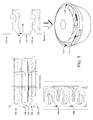
- a conventional diffuser 100 of a conventional pump stage includes a nesting feature 102 for centering or radially locating a next adjacent pump stage 104.
- the nesting feature compensates part of the outer wall 106 of the diffuser 100 so that compressive load on the diffuser 100 is carried only by part 108 of the outer wall of the diffuser 100. The remainder of the wall is required for a locating pilot.
- the axial load-bearing capacity of the diffuser is weakened.
- an example diffuser 110 supports the next adjacent diffuser 112 across the entire wall cross-section or outer wall thickness 114 of the diffuser 110. Since the nesting feature 102 has been removed from the outer wall 116, the adjacent diffusers 110 & 112 are radially located using a tip feature 118 on or near the leading edges of the diffuser vanes. This allows the entire diffuser wall to carry axial load, and none of the outer wall thickness is wasted for radial locating features.
- all diffuser nesting features are removed from the outer wall 116 of the diffuser 110 and radial locating is achieved entirely by controlling fit of mating parts from inside the pump housing. This also leaves the entire outer wall 116 of the diffuser 110 available to carry the axial compressive load.
- diffuser mating faces are tapered so that the full cross-section of each outer wall 116 is available to carry axial load while also providing radial location of adjacent diffusers.
- some main functions of the conventional "cast” pump diffuser are separated out into corresponding hardware components, to create a composite diffuser.
- the tubular "wall" of the diffuser is separated from the "body” of the diffuser, which contains the vaned flow passages.
- the geometric design of a conventional diffuser is complex with intricate flow channels.
- conventional diffusers are traditionally made out of castings as a whole unit having uniform physical properties. But functionally, different sections of a diffuser serve different purpose, i.e., the diffuser wall acts as the structural member to carry axial load and the flow region does the hydraulic work.
- An example composite diffuser can be assembled from a tubular or cylindrical load bearing component or module, and a flow diffusing component or module.
- the two modules can be manufactured separately and assembled together to obtain the final diffuser geometry.
- the load bearing module can be of simple cylindrical geometry, which can be made of stiffer material to increase its load bearing capacity, and the flow diffusing module can be manufactured separately, using methods focused on improving hydraulic efficiency.
- the two-piece construction enables high-strength tubing to be used for the outer wall of the diffuser, which provides the structural strength in a multi-stage centrifugal pump.
- the flow diffusing module can be manufactured as a standard casting followed by machining or by other advanced manufacturing techniques including but not limited to powder metallurgy, powder injection molding, etc. depending on the required material, geometric complexity, surface finish, accuracy, cost, etc., of the final part.
- the load bearing module can be machined-off from commercially available tubular raw materials, or by other means, including but not limited to forging, roll forming, etc. to have suitable mechanical properties.
- the two modules can be fitted together by employing a suitable metal joining process including but not limited to a threaded joint, an interference fit, a friction weld, etc.
- a suitable metal joining process including but not limited to a threaded joint, an interference fit, a friction weld, etc.
- the joint has sufficient shearing strength to overcome the reaction torque, in order to prevent the diffuser from spinning during the operation of the pump.
- Fig. 2 shows an example diffuser 200 assembled as at least one load bearing component 202 and a flow diffusing component 204.
- a shoulder 206 on the cast body of the flow diffusing component 204 is sandwiched between diffuser "tubes" (the load bearing components 202) to form a single diffuser 200.
- Fig 3 shows another implementation of an example diffuser 300, in which the load bearing component 302 is a continuous tube.
- the cast body of the flow diffusing component 304 is located inside the continuous diffuser "tube" (the load bearing component 302) to form a single diffuser 300.
- the cast body can be fixed to the continuous tube load bearing component 302 by various means, for example, brazing, press-fit, welding, adhesives, swaging, and so forth.
- the cast body of the flow diffusing component 304 is joined to the continuous tubular load bearing component 302 using a tapered fit.
- a wedged or tapered sleeve 400 may be used to secure the flow diffusing component 304 to the load bearing component 302.
- a slot 402 in the tapered sleeve 400 allows for slight radial change, radial growth, and thermal expansion and contraction, as well as adjustment in the tightness of the fit, with more axial compression forcing a greater radius of the tapered sleeve 400.
- a sintered surface or a roughened surface 404 having a high coefficient of friction may also be used to lock the tapered sleeve 400 against the inside diameter of the load bearing component 302.
- a wedge-shaped diffuser and sleeve expand the sleeve outside diameter to lock the flow diffusing component 304 in place during assembly.
- greater down-thrust forces lead to higher radial push, securing the flow diffusing component 304 even more firmly in place.
- a 0.08 inch radial translation can be achieved using a 1.55 degree taper over a 1.5 inch axial length.
- Fig. 5 shows another implementation, in which a ledge or shoulder 500 is provided in the continuous tubular load bearing component 502 for each flow diffusing stage 504 included.
- Each ledge or shoulder 500 enables a corresponding flow diffusing component 504 to transfer downthrust forces to the load bearing component 502.
- a spot weld or other fixation means is used to arrest the flow diffusing component 504 from moving up away from the ledge or shoulder 500 during upthrust.
- the axial stiffness of an example diffuser design is increased by replacing the load carrying module with a high stiffness material in order to withstand higher compressive loads, and at the same time to reduce the diffuser wall thickness, which then provides a larger design space, i.e., a higher volume pump chamber, for example, or larger vanes.
- Ni-Resist walls of a diffuser are replaced with tubular alloys having a higher elastic modulus.
- a multistage pump design benefits from the stack of diffusers being held rigidly under compression.
- a residual compression can be built into the stack during manufacture to create a highly compressed diffuser stack 602. By applying an amount of torque to the head and base, for example, with respect to housing during pump assembly, this induced residual compression can prevent diffuser spinning during operation.
Landscapes
- Engineering & Computer Science (AREA)
- Mechanical Engineering (AREA)
- General Engineering & Computer Science (AREA)
- Structures Of Non-Positive Displacement Pumps (AREA)
Applications Claiming Priority (2)
| Application Number | Priority Date | Filing Date | Title |
|---|---|---|---|
| US201361807023P | 2013-04-01 | 2013-04-01 | |
| US14/171,653 US9683571B2 (en) | 2013-04-01 | 2014-02-03 | Centrifugal pump stage with increased compressive load capacity |
Publications (1)
| Publication Number | Publication Date |
|---|---|
| EP2787219A2 true EP2787219A2 (fr) | 2014-10-08 |
Family
ID=50397003
Family Applications (1)
| Application Number | Title | Priority Date | Filing Date |
|---|---|---|---|
| EP14162928.7A Withdrawn EP2787219A2 (fr) | 2013-04-01 | 2014-03-31 | Étage de pompe centrifuge présentant une plus grande capacité de charge de compression |
Country Status (3)
| Country | Link |
|---|---|
| US (1) | US9683571B2 (fr) |
| EP (1) | EP2787219A2 (fr) |
| BR (1) | BR102014007858A2 (fr) |
Cited By (1)
| Publication number | Priority date | Publication date | Assignee | Title |
|---|---|---|---|---|
| US10873266B2 (en) | 2016-05-13 | 2020-12-22 | Sew-Eurodrive Gmbh & Co., Kg | Converter system having an AC/DC converter, and method for operating a converter system |
Families Citing this family (5)
| Publication number | Priority date | Publication date | Assignee | Title |
|---|---|---|---|---|
| CN107100896A (zh) * | 2017-05-25 | 2017-08-29 | 合肥皖化电泵有限公司 | 一种具有高效扩散器的炉水循环泵 |
| US10989219B2 (en) | 2019-02-04 | 2021-04-27 | Honeywell International Inc. | Diffuser assemblies for compression systems |
| EP4055252B1 (fr) * | 2019-11-08 | 2026-04-01 | Baker Hughes Oilfield Operations, LLC | Éléments de centralisation dans une pompe électrique submersible |
| CN113027812B (zh) * | 2021-03-23 | 2022-12-02 | 西安航天泵业有限公司 | 一种径向剖分两端支撑式两级低温泵的装配工艺 |
| EP4392678A4 (fr) * | 2021-08-25 | 2025-07-23 | Waterax Inc | Diffuseur à croisement composite pour pompe centrifuge, pompe centrifuge comprenant ledit diffuseur et procédé de fabrication correspondant |
Family Cites Families (5)
| Publication number | Priority date | Publication date | Assignee | Title |
|---|---|---|---|---|
| US3070026A (en) * | 1958-12-03 | 1962-12-25 | Tait Mfg Co The | Pumps |
| US3171355A (en) * | 1963-03-14 | 1965-03-02 | Dresser Ind | Well pump |
| DE2618829C3 (de) * | 1976-04-29 | 1983-03-03 | Klein, Schanzlin & Becker Ag, 6710 Frankenthal | Lagerung einer mehrstufigen Kreiselpumpe |
| US4406582A (en) * | 1981-05-19 | 1983-09-27 | Marley-Wylain Company | Submersible pump discharge head |
| US4806083A (en) * | 1986-10-21 | 1989-02-21 | The Marley-Wylain Company | Submersible pump with expanded foam housing |
-
2014
- 2014-02-03 US US14/171,653 patent/US9683571B2/en not_active Expired - Fee Related
- 2014-03-31 EP EP14162928.7A patent/EP2787219A2/fr not_active Withdrawn
- 2014-04-01 BR BR102014007858A patent/BR102014007858A2/pt not_active IP Right Cessation
Non-Patent Citations (1)
| Title |
|---|
| None |
Cited By (2)
| Publication number | Priority date | Publication date | Assignee | Title |
|---|---|---|---|---|
| US10873266B2 (en) | 2016-05-13 | 2020-12-22 | Sew-Eurodrive Gmbh & Co., Kg | Converter system having an AC/DC converter, and method for operating a converter system |
| US11437920B2 (en) | 2016-05-13 | 2022-09-06 | Sew-Eurodrive Gmbh & Co. Kg | Converter system having an AC/DC converter, and method for operating a converter system |
Also Published As
| Publication number | Publication date |
|---|---|
| BR102014007858A2 (pt) | 2016-08-23 |
| US20140294575A1 (en) | 2014-10-02 |
| US9683571B2 (en) | 2017-06-20 |
Similar Documents
| Publication | Publication Date | Title |
|---|---|---|
| US9683571B2 (en) | Centrifugal pump stage with increased compressive load capacity | |
| EP3387261B1 (fr) | Rouet caréné produit par fabrication additive comprenant des cavités dans le moyeu et dans la virole | |
| CN106687688B (zh) | 用于往复泵的轴承系统及其装配方法 | |
| US8967985B2 (en) | Metal disk stacked stator with circular rigid support rings | |
| US4322200A (en) | Heavy duty impeller | |
| CN113182636B (zh) | 一种承力机匣组件真空钎焊用工装的使用方法 | |
| EP1083345B1 (fr) | Arbre composite à haute rigidité | |
| CN106795779B (zh) | 用于飞行器涡轮机的包括可移除定心基座的两部件的组件 | |
| CN101338842B (zh) | 软管接头金属部件的制造方法 | |
| US10590933B2 (en) | Rotary compressor | |
| JP5782022B2 (ja) | 金属部材結合装置 | |
| CN111371213B (zh) | 压缩机转子、压缩机和冷媒循环系统 | |
| CN115889970B (zh) | 一种燃气轮机压气机鼓筒惯性摩擦焊接的工装 | |
| SE525778C2 (sv) | Hydromekanisk fastspänningsanordning med expanderingsorgan med samverkande konytor | |
| CN109909433A (zh) | 一种离心压气机的加工工装及加工方法 | |
| CN118148909B (zh) | 一种双金属缸套及其带压替换式安装工具 | |
| US10393174B2 (en) | Thrust disc, magnetic bearing and apparatus | |
| US4155151A (en) | Heavy duty impeller and method of fabricating the same | |
| CN212296846U (zh) | 泥浆泵用双皮碗活塞 | |
| CN108644111B (zh) | 方便拆装的螺杆泵 | |
| CN209458197U (zh) | 一种单级磁力离心泵的轴向力平衡结构 | |
| CN118979887B (zh) | 一种静片隔离环一体化组件及其应用 | |
| CN207111429U (zh) | 用于压缩机的支撑件和具有其的压缩机 | |
| AU2016278867B2 (en) | Casing for a turbomachine | |
| US20090007774A1 (en) | Aircraft actuator piston |
Legal Events
| Date | Code | Title | Description |
|---|---|---|---|
| PUAI | Public reference made under article 153(3) epc to a published international application that has entered the european phase |
Free format text: ORIGINAL CODE: 0009012 |
|
| 17P | Request for examination filed |
Effective date: 20140331 |
|
| AK | Designated contracting states |
Kind code of ref document: A2 Designated state(s): AL AT BE BG CH CY CZ DE DK EE ES FI FR GB GR HR HU IE IS IT LI LT LU LV MC MK MT NL NO PL PT RO RS SE SI SK SM TR |
|
| AX | Request for extension of the european patent |
Extension state: BA ME |
|
| RIN1 | Information on inventor provided before grant (corrected) |
Inventor name: LAKSHMANAN, NARAYANAN Inventor name: MORRISON, TONY R. Inventor name: EKAMBARAM, RAJU Inventor name: CHEAH, KEAN WEE Inventor name: CHANG, LYE HENG Inventor name: ESLINGER, DAVID MILTON |
|
| STAA | Information on the status of an ep patent application or granted ep patent |
Free format text: STATUS: THE APPLICATION IS DEEMED TO BE WITHDRAWN |
|
| 18D | Application deemed to be withdrawn |
Effective date: 20181002 |