EP2787220B1 - Élément de fixation pour la construction de meubles - Google Patents
Élément de fixation pour la construction de meubles Download PDFInfo
- Publication number
- EP2787220B1 EP2787220B1 EP14163344.6A EP14163344A EP2787220B1 EP 2787220 B1 EP2787220 B1 EP 2787220B1 EP 14163344 A EP14163344 A EP 14163344A EP 2787220 B1 EP2787220 B1 EP 2787220B1
- Authority
- EP
- European Patent Office
- Prior art keywords
- holding
- holding part
- adjustment part
- fitting element
- furniture
- Prior art date
- Legal status (The legal status is an assumption and is not a legal conclusion. Google has not performed a legal analysis and makes no representation as to the accuracy of the status listed.)
- Active
Links
Images

Classifications
-
- F—MECHANICAL ENGINEERING; LIGHTING; HEATING; WEAPONS; BLASTING
- F16—ENGINEERING ELEMENTS AND UNITS; GENERAL MEASURES FOR PRODUCING AND MAINTAINING EFFECTIVE FUNCTIONING OF MACHINES OR INSTALLATIONS; THERMAL INSULATION IN GENERAL
- F16B—DEVICES FOR FASTENING OR SECURING CONSTRUCTIONAL ELEMENTS OR MACHINE PARTS TOGETHER, e.g. NAILS, BOLTS, CIRCLIPS, CLAMPS, CLIPS OR WEDGES; JOINTS OR JOINTING
- F16B12/00—Jointing of furniture or the like, e.g. hidden from exterior
- F16B12/10—Jointing of furniture or the like, e.g. hidden from exterior using pegs, bolts, tenons, clamps, clips, or the like
- F16B12/12—Jointing of furniture or the like, e.g. hidden from exterior using pegs, bolts, tenons, clamps, clips, or the like for non-metal furniture parts, e.g. made of wood, of plastics
- F16B12/24—Jointing of furniture or the like, e.g. hidden from exterior using pegs, bolts, tenons, clamps, clips, or the like for non-metal furniture parts, e.g. made of wood, of plastics using separate pins, dowels, or the like
-
- A—HUMAN NECESSITIES
- A47—FURNITURE; DOMESTIC ARTICLES OR APPLIANCES; COFFEE MILLS; SPICE MILLS; SUCTION CLEANERS IN GENERAL
- A47B—TABLES; DESKS; OFFICE FURNITURE; CABINETS; DRAWERS; GENERAL DETAILS OF FURNITURE
- A47B2230/00—Furniture jointing; Furniture with such jointing
- A47B2230/0029—Dowels
- A47B2230/0051—Two-piece dowels
Definitions
- Object of the present invention is to provide an improved fastener for furniture, especially with regard to a functionally correct provision of the fastener for pre-assembly and the subsequent error-free adjustment to set up the attachment function.
- the invention relates to a fastener for furniture, in particular a furniture fastener, with a holding part, which can be introduced for a fastening function in a recessed receiving volume and then adjustable in a holding position of the fastener by a widening of a holding portion on the holding part, and with a control part tuned to the holding part such that with a linear relative movement between the holding part and the functionally correct position attached to the holding part, the holding position can be established, wherein the actuating part remains in the holding position on the holding part.
- the essence of the invention is that on the control part over an outer contour of the actuating part projecting stop means are provided, wherein the stop means determine a position of insertion of the actuating part on the holding part, in which the functionally correct on the holding part mounted actuating part is inserted on the holding part and the control part and the holding part to each other are held, wherein in the insertion position of the holding portion is not adjusted.
- the fastening element In the first of the two separate parts or from the holding and adjusting the existing fastener element is properly attached to the holding part in a first step z. B. plugged so that it is automatically held on the holding part. The attachment function causing a stop position is not reached. In the state prepared in this way, the fastening element can be mounted or preassembled at any desired location, for example.
- the adjusting and the holding part can be held by friction or otherwise together. In the established by the linear relative movement holding position of the fastener this is clamped in the receiving volume by the expanded holding portion.
- the adjustment of the holding portion by the linear retraction or indentations of the adjusting member is effected in particular by an expansion to the outside or a spreading of the holding portion on the holding part.
- the holding portion is forcibly pressed against outer adjacent walls of the recessed receiving volume, for example, a blind hole in a wood material.
- the linear relative movement to achieve the holding position with the adjusting member is advantageously carried out in the insertion direction in which the actuating part can be moved to the holding part in order in the right position to be held.
- the stop means are over an envelope surface of the actuating part to the outside and can thus be effective when attaching the control part on the holding part.
- an anti-rotation device is provided, with which a rotational movement between the actuating part and the holding part is prevented around a longitudinal axis of the fastener in functionally correct attached to the holding part actuator.
- the rotation is especially important if by means of a screw which can be inserted in the longitudinal direction of the fastener in the control part, which is infected positionally correct on the holding part, by the screwing in the relative movement of the actuating and holding part is realized.
- the screw is only rotatable, but fixed in the longitudinal direction. Also, the holding part must be secured against rotation in this approach against rotation relative to adjacent sections.
- the anti-rotation guide sections comprises, which contribute to the leadership of the linear relative movement between the holding part and the control part and which are effective for adjusting the holding portion by a widening of the holding portion.
- cooperating sections can be provided on the setting part and on the holding part be, which circumferentially considered to the longitudinal axis of the fastener form a stop and a counter-stop and thus prevent twisting, but the facing portions can slide past each other in the longitudinal direction mutually leading, which takes place in the linear relative movement between the actuating and holding part.
- An insertion portion is present on the setting part, which engages with the functionally correct attachment of the adjusting part on the holding part in a receptacle on the holding part, wherein the stop means comprise at least one stop element which comes into abutment against a mating portion, without an adjustment of the holding portion.
- the introduction section on the adjusting part and the receptacle on the holding part are matched to one another and to the stop element, that the adjusting part is inserted so far into the holding part, that in the stop position of the stop element on the counter section, the adjusting part and the holding part are held together without the holding section undergoes an adjustment.
- the introduction section z. B. on the outside of the adjusting part is in the direction of insertion in particular widening or slightly conically widening formed, as well as in appropriate form the corresponding counter portion or the recording on the holding part.
- the at least one stop element is provided in such a way that starting from a functionally correct attached to the holding part actuator via the stop means, a resistance to a further linear relative movement between the actuating part and the holding part in Ansteckides to set up the holding position is provided.
- a person may be infected by the Adjusting the holding part to determine that the desired AnsteckSullivan the adjusting part is reached on the holding part.
- the actuator is then included in its correct insertion depth in the recording. Until reaching this insertion depth, the actuating part or its insertion section slides without resistance in the holding part or its inclusion.
- the at least one stop element is formed protruding outward on the actuating part.
- the stop element may be pin-shaped or comparatively narrow and elongated.
- An advantageous modification of the subject invention provides that exactly two protruding stop elements are present on the control part.
- the two stop elements with respect to a longitudinal axis of the actuating part are advantageously opposite to each other above.
- an opposite section on the holding part can serve an end face.
- the end face may be formed, for example, enclosing the recessed receptacle on the holding part.
- the stop elements are particularly similar. In principle, more than two stop elements may be present.
- the counter portion and the at least one stop element are coordinated such that, starting from the insertion position in the linear relative movement of the actuating part and holding part for setting the holding position, the at least one stop element moves away from the above position.
- the further linear relative movement is possible.
- a further impressions of the actuating part in the holding part is removed with the moving away of the stop element of the resistance by the stop element in the stop position against a relative movement of the actuating part and holding part in Ansteckraum.
- the stop element is present on the fastening element in such a way that, when a pushing-in force acting on the stop element is exceeded, the stop element, for example, articulates or is bent over in an articulated manner.
- the at least one stop element is provided on the fastening element such that the at least one stop element can be deflected and / or at least partially sheared in cooperation with the counterpart section during the relative movement of the setting part and holding part to set up the holding position.
- the bending and shearing can also be superimposed possible or first a bending and then at least a partial shearing done. A complete shearing of the stop element is possible.
- a matched to the at least one stop element cavity on the fastening element is formed such that the at least one stop element is immersed in the cavity when the relative movement between the holding part and the holding part functionally correct mounted adjusting part for setting the holding position.
- the cavity is in particular present on the part on which the at least one stop element is formed.
- two stop elements are present on the setting part, wherein each stop element is associated with a cavity or a recessed formed area.
- the cavity is related to a direction of insertion of the actuating part trailing the stop element or adjacent to the point at which the stop element protrudes.
- the stop element can be bent or sheared off at this point and automatically pressed with the relative movement of the actuating and holding part in the cavity.
- guiding portions cooperating with one another on the holding part and the setting part are present in such a way that the linear relative movement between the holding part and the setting part for the adjustment of the holding section is guided by the guide sections can be specified.
- a force effect in the direction transverse thereto or provided to the outside over the guide portions for example in the direction of relative movement obliquely aligned surfaces on the control part and mating surfaces on the holding part, so that widened by a wedge effect with the movement of these inclined surfaces of the holding section to the outside or spread.
- the guide portions advantageously comprise a conical or round-conical outer side on the setting part or on its insertion portion and on the holding part on the conical outside in the relative movement in abutting inside on the receiving of the holding part, wherein the inclination or spatial orientation of the outside and the inside are matched.
- the receptacle can have, for example, two sections or segments which can expand elastically outwards.
- the holding portion is formed by these sections, wherein externally a ribbed structure may be formed, whereby the pressing and Einhak Koch the holding portion is improved against walls of the receiving volume.
- the guide portions may be present on the rotation, wherein the guide portions contribute to the rotation and the expansion of the holding portion.
- the guide sections spatially mutually angled aligned guide surfaces which serve to guide the relative movement between the actuating part and the holding part and / or for adjusting the holding portion by a widening of the holding portion.
- the insertion section is provided on the control part with guide portions.
- a holding, positioning and adjustment function is provided with the introduction section.
- the invention also relates to a front hook for a furniture front part, which is connectable to a furniture side part over the front part fixable on the front door hook, wherein for fixing the front hook on the furniture front part, a fastening element for fixing the front hook on the furniture front part according to one of the aforementioned embodiments.
- a fastening element for fixing the front hook on the furniture front part according to one of the aforementioned embodiments.
- projecting pin on the holding part in prepared openings on the front hook to achieve a rotationally fixed attachment of the fastener on the front hook.
- the invention extends to furniture with furniture components, wherein fastening means are provided for the assembly of the furniture components, wherein the fastening means comprise a fastening element according to one of the above-mentioned embodiments.
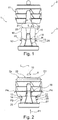
- a fastener according to the invention designed as a fixing dowel 1 comprises a holding part 2 and a matching adjusting part 3.
- FIG. 1 are the holding part 2 and the adjusting part 3 spaced from each other, wherein the holding part 2 and the adjusting part 3 are aligned with respect to each other positionally, so that moved by merging the holding part 2 and the adjusting part 3, for example by the adjusting member 3 in the direction of arrow P1 to the holding part 2 is, the two parts 2 and 3 are plugged together.
- FIG. 2 shows the mated state of the holding part 2 and setting part 3, wherein the adjusting part 3 is attached to the holding part 2 functionally correct.
- FIG. 3 shows the expansion dowel 1 in a holding position of the expansion anchor 1, in which the holding part 2 is held clamped in a corresponding, in particular cylindrically shaped opening or a prepared receiving volume (not shown), for example in a furniture part area.
- FIG. 2 The elastic expansion or spreading of a holding portion 11 with three circumferentially extending serrated ribs on the holding part 2 is in FIG. 2 indicated by arrows P4.
- the holding section 11 are set away from the outside or from the longitudinal axis L of the expansion anchor 1.
- FIG. 7 changed.
- the holding portion 11 can be pressed against the outside walls of a receiving volume and clamp the expansion dowel 1 in the relevant component.
- stop elements 12, 13 are over the length of the adjusting part 3 approximately centrally and projecting outwardly as a pin-shaped sections on the control part 3 available.
- the stop elements 12, 13 extend to the outside via an envelope H of the actuating part 3 via.
- the stop elements 12, 13 come in the insertion position according to FIG. 2 at an end portion 14 on the holding part 2 in Appendix.
- the outer wall 16 enclosing a passage opening 29 of the setting part 3 forms a positive or frictional connection with the holding part 2 on a frusto-conical plug-in section 15.
- the holding part 2 has a receptacle 17 with a through opening 28 on the holding part 2 bounding wall.
- On expansion dowel 1 also a rotation 18 is provided to rotate between the holding part 2 and the setting part 3 in the mutually infected state FIG. 2 or in the holding state according to FIG. 3 to prevent.
- the anti-rotation device 18 comprises two laterally outwardly on the adjusting part 3 protruding opposite rib-like guide cone 19, 20 which extend with its front end portion rounded into the insertion portion 15.
- the guide cone 19, 20 are tuned to engage in slots 21, 22 in the holding portion 11, wherein the slots 21, 22 are formed by a transversely extending through the holding part 2 recess.
- Each guide cone 19, 20 has obliquely to the longitudinal axis L against the insertion direction P1 flared edges 23 and 24, which come when inserting the adjusting part 3 in the holding part 2 at slot walls of each associated slot 21 and 22 into abutment and also essential to widening contribute the holding portion 11.
- the stop elements 12, 13 Upon reaching the stop position according to FIG. 3 the stop elements 12, 13 according to the movement arrows P2 and P3 (see FIG. 2 bent or at least partially sheared off, wherein the stop elements 12 and 13 in each case an associated cavity 25 and 26 immerse.
- the cavities 25, 26 are adjacent to the stop elements 12 and 13 on the adjusting part 3 matched to the stop elements 12 and 13 are formed.
- the bent or sheared stop elements 12 and 13 no obstacle to reach the holding position according to FIG. 3 more ready. Because the sheared or bent stop elements 12 and 13 can be found completely in the cavities 25 and 26, so that the holding position according to FIG. 3 is easily set up without jamming the stop members 12 and 13 between the actuating part 3 and the holding part 2.
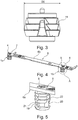
- FIGS. 4 to 7 is a front hook 6 with two expansion anchors 1 identical expansion dowels 1a and 1b shown.
- the respective screw 4 or 5 is thereby centrally inserted into the opening 28 in an end face 2a of the holding part 2 until an external thread of the screw 4 or 5 engages in the central passage opening 29 in the setting part 3 or cuts into it.
- By further screwing the screw 4 and 5 is then locked at the front hooks 6 via two insertion pins 9 and 10 inserted holding part 2, the control part 3 to the holding part 2 and thereby brought into the spread holding position.
- the two expansion dowels 1a and 1b are accordingly used for attaching the front hook 6 to a furniture part, wherein the furniture part prepared round holes for receiving the two rear on a back 6a on the front hook 6 projecting expansion dowel 1a, 1b are present, in which the expansion dowel 1a, 1b with the reaching of the holding position.
- front hooks 6 are for mounting the two expansion dowel 1a, 1b two round holes 7 and 8 prepared present and back additionally next to each two not visible in the figures wells, in which the two insertion pins 9, 10th fit exactly.
- the expansion dowel 1a, 1b in the assembled arrangement according to FIG. 2 at the back 6a of the front hook 6 infected, wherein the two opposite on the front side 2a Einsteckzapfen 9, 10 engage in the prepared existing recesses and hold the expansion dowel 1a, 1b against rotation on the front hook 6.
- the screws 4 and 5 are screwed into the two expansion dowels 1a, 1b or into the through-opening 29 on the setting part 3 from a front side 6b of the front hook 6, so that the arrangement according to FIG FIG. 5 is set up.
- the holding section 11 on the expansion anchor 1 is in this case in its initial position or in its non-expanded or not spread orientation according to FIG. 2 ,
Landscapes
- Engineering & Computer Science (AREA)
- General Engineering & Computer Science (AREA)
- Mechanical Engineering (AREA)
- Connection Of Plates (AREA)
- Furniture Connections (AREA)
Claims (12)
- Élément de fixation (1) pour la construction de meubles, en particulier élément de fixation de meuble, comprenant une partie de retenue (2) qui, pour une fonction de fixation, peut être introduite dans un volume de logement creux puis peut être ajustée dans une position de retenue de l'élément de fixation (1) par un élargissement d'une section de retenue (11) de la partie de retenue (2), et un organe de réglage (3) adapté à la partie de retenue (2) de telle sorte que la position de retenue peut être établie au moyen d'un mouvement relatif linéaire entre la partie de retenue (2) et l'organe de réglage (3) monté correctement sur la partie de retenue (2), l'organe de réglage (3), dans la position de retenue, restant sur la partie de retenue (2), des moyens de butée qui saillent du contour extérieur de l'organe de réglage (3) étant prévus sur l'organe de réglage (3), avec au moins un élément de butée (12, 13) conçu saillant vers l'extérieur sur l'organe de réglage (3) et venant en butée contre une section complémentaire (14), les moyens de butée définissant une position d'enfichage de l'organe de réglage (3) sur la partie de retenue (2), position dans laquelle l'organe de réglage (3) monté correctement sur la partie de retenue (2) est enfiché sur la partie de retenue (2) et l'organe de réglage (3) et la partie de retenue (2) sont retenus l'un sur l'autre, caractérisé en ce que, dans la position d'enfichage, la section de retenue (11) n'est pas ajustée et les éléments de butée (12, 13) constituent un obstacle empêchant d'atteindre la position de retenue.
- Élément de fixation selon la revendication 1, caractérisé en ce qu'il est prévu une protection anti-rotation (18) empêchant, lorsque l'organe de réglage (3) est monté correctement sur la partie de retenue (2), un mouvement de rotation entre l'organe de réglage (3) et la partie de retenue (2) autour d'un axe longitudinal de l'élément de fixation (1).
- Élément de fixation selon la revendication 2, caractérisé en ce que la protection anti-rotation (18) comprend des sections de guidage (23, 24), lesquelles contribuent au guidage du mouvement relatif linéaire entre la partie de retenue (2) et l'organe de réglage (3), et lesquelles ont pour effet d'ajuster la section de retenue (11) par un élargissement de la section de retenue (11).
- Élément de fixation selon l'une des revendications précédentes, caractérisé en ce qu'exactement deux éléments de butée (12, 13) saillant sont présents sur l'organe de réglage (3).
- Élément de fixation selon l'une des revendications précédentes 1 à 3, caractérisé en ce que la section complémentaire (14) et le au moins un éléments de butée (12, 13) sont adaptés l'un à l'autre de telle manière que, partant de la position d'enfichage, lors du mouvement relatif linéaire de l'organe de réglage (3) et de la partie de retenue (2) pour établir la position de retenue, le au moins un élément de butée (12, 13) s'écarte de la position en saillie.
- Élément de fixation selon l'une des revendications précédentes 1 à 3 et 5, caractérisé en ce que le au moins un élément de butée (12, 13) est présent sur l'élément de fixation (1) de telle manière que le au moins un élément de butée (12, 13), en coopération avec la section complémentaire (14) lors du mouvement relatif de l'organe de réglage (3) et de la partie de retenue (2) pour l'établissement de la position de retenue, peut être dévié et/ou au moins en partie cisaillé.
- Élément de fixation selon l'une des revendications précédentes 1 à 3, 5 et 6, caractérisé en ce qu'une cavité (25, 26) adaptée à l'au moins un élément de butée (12, 13) est ménagée sur l'élément de fixation (1) de telle manière que le au moins un élément de butée (12, 13) s'enfonce dans la cavité (25, 26) lorsque le mouvement relatif entre la partie de retenue (2) et l'organe de réglage (3) monté correctement sur la partie de retenue (2) est réalisé pour l'établissement de la position de retenue.
- Élément de fixation selon l'une des revendications précédentes, caractérisé en ce que des sections de guidage sont présentes sur la partie de retenue (2) et l'organe de réglage (3) et coopèrent les unes avec les autres de telle manière qu'avec les sections de guidage, le mouvement relatif linéaire entre la partie de retenue (2) et l'organe de réglage (3) peut être prédéfini de manière guidée pour l'ajustement de la section de retenue (11).
- Élément de fixation selon la revendication 8, caractérisé en ce que les sections de guidage comprennent des surfaces de guidage orientées en faisant dans l'espace un angle les unes par rapport aux autres, lesquelles surfaces servent à guider le mouvement relatif entre l'organe de réglage (3) et la partie de retenue (2) et/ou à ajuster la section de retenue (11) par un élargissement de la section de retenue (11).
- Élément de fixation selon l'une des revendications précédentes, caractérisé en ce que la section d'introduction (15) sur l'organe de réglage (3) est pourvue de sections de guidage.
- Crochet de façade (6) pour une façade de meuble qui peut être reliée à une partie latérale de meuble au moyen des crochets de façade (6) pouvant être fixés sur la façade de meuble, caractérisé en ce que pour fixer le crochet de façade (6) sur la façade de meuble, un élément de fixation (1) destiné à fixer le crochet de façade (6) sur la façade de meuble selon l'une des revendications précédentes est présent.
- Meuble comprenant des composants de meuble, des moyens de fixation pour l'assemblage des composants de meuble étant prévus, caractérisé en ce que les moyens de fixation comprennent un élément de fixation (1) selon l'une des revendications 1 à 2.
Applications Claiming Priority (1)
| Application Number | Priority Date | Filing Date | Title |
|---|---|---|---|
| DE202013003073.9U DE202013003073U1 (de) | 2013-04-04 | 2013-04-04 | Befestigungselement für den Möbelbau |
Publications (3)
| Publication Number | Publication Date |
|---|---|
| EP2787220A2 EP2787220A2 (fr) | 2014-10-08 |
| EP2787220A3 EP2787220A3 (fr) | 2015-02-18 |
| EP2787220B1 true EP2787220B1 (fr) | 2017-02-01 |
Family
ID=50424115
Family Applications (1)
| Application Number | Title | Priority Date | Filing Date |
|---|---|---|---|
| EP14163344.6A Active EP2787220B1 (fr) | 2013-04-04 | 2014-04-03 | Élément de fixation pour la construction de meubles |
Country Status (2)
| Country | Link |
|---|---|
| EP (1) | EP2787220B1 (fr) |
| DE (1) | DE202013003073U1 (fr) |
Families Citing this family (3)
| Publication number | Priority date | Publication date | Assignee | Title |
|---|---|---|---|---|
| DE202015105329U1 (de) * | 2015-10-08 | 2017-01-11 | Grass Gmbh | Dübelanordnung für eine Vorrichtung zum Verbinden zweier Möbelelemente |
| AT519915B1 (de) * | 2017-05-11 | 2020-11-15 | Blum Gmbh Julius | Dübel zum Befestigen von Beschlagteilen |
| US11898584B2 (en) | 2020-02-07 | 2024-02-13 | Hni Technologies Inc. | Tool-less fastening system |
Family Cites Families (6)
| Publication number | Priority date | Publication date | Assignee | Title |
|---|---|---|---|---|
| DE2457172C2 (de) * | 1974-12-04 | 1984-09-27 | Paul Hettich & Co, 4983 Kirchlengern | Montageplatte für einen Scharnierarm |
| DE2701510A1 (de) * | 1977-01-15 | 1978-07-20 | Upat Max Langensiepen Kg | Duebel mit huelse und spreizkoerper |
| DE2815013A1 (de) * | 1977-04-15 | 1978-10-26 | Blum Gmbh Julius | Montageplatte |
| DE9307729U1 (de) * | 1993-05-21 | 1993-11-04 | Solidor Kunststoff und Metall Produktionsgesellschaft mbH (SKM), 37308 Heilbad Heiligenstadt | Spreizkörper |
| DE19915119B4 (de) * | 1999-04-01 | 2006-11-16 | Karl Simon Gmbh & Co. Kg | Montageelement für den Möbelbau |
| DE10229300B3 (de) * | 2002-06-29 | 2004-03-25 | Werthmüller Systeme Geisa GmbH & Co.KG | Verbindungssystem für Bauteile, insbesondere für Möbelteile |
-
2013
- 2013-04-04 DE DE202013003073.9U patent/DE202013003073U1/de not_active Expired - Lifetime
-
2014
- 2014-04-03 EP EP14163344.6A patent/EP2787220B1/fr active Active
Also Published As
| Publication number | Publication date |
|---|---|
| DE202013003073U1 (de) | 2014-07-08 |
| EP2787220A2 (fr) | 2014-10-08 |
| EP2787220A3 (fr) | 2015-02-18 |
Similar Documents
| Publication | Publication Date | Title |
|---|---|---|
| EP2742199B1 (fr) | Système de fixation pour fixer une pièce sur une rainure d'une fenêtre, d'une porte ou analogue | |
| DE202015008847U1 (de) | Befestigungsvorrichtung | |
| EP3122981B1 (fr) | Dispositif d'étanchéité et moyen pour fixation | |
| DE102012219154A1 (de) | Lösbare Verbindungsvorrichtung für die werkzeuglose Montage | |
| DE102013111400A1 (de) | Befestigungsvorrichtung für zwei Befestigungszustände | |
| WO2007014697A1 (fr) | Element de fixation a inserer dans un alesage | |
| WO2016146272A1 (fr) | Élément de maintien pour une poignée de porte ou de fenêtre et agencement d'une poignée de porte ou de fenêtre au niveau d'une ouverture de réception d'un cadre de fenêtre, d'un battant de porte ou similaire | |
| EP3476252A1 (fr) | Dispositif de retenue pour un rayonnage sur une paroi de rayonnage et rayonnage doté d'un tel dispositif de retenue | |
| EP2787220B1 (fr) | Élément de fixation pour la construction de meubles | |
| EP3401556A1 (fr) | Connection de panneaux frontaux | |
| DE19642914C2 (de) | Dübel | |
| DE60200329T2 (de) | Regalbodenstütze für eine schnelle Montage, für Möbel und dergleichen | |
| AT519920B1 (de) | Befestigungsvorrichtung | |
| DE102015113737B3 (de) | Sensor | |
| EP3592993A1 (fr) | Raccord de serrage et ensemble de fixation comprenant ledit raccord | |
| EP1473468B1 (fr) | Connecteur enfichable | |
| DE202007001276U1 (de) | Vorrichtung zur Befestigung eines Beschlagteils | |
| EP1735539B1 (fr) | Systeme de fixation | |
| EP3291395B1 (fr) | Appareil d'installation pour montage au plafond | |
| EP3093937A1 (fr) | Partie de socle pour appareils d'installation électriques | |
| EP0058709A1 (fr) | Boulon d'ancrage | |
| DE102014103637B4 (de) | Topflocheinsatz, Blendenbefestigungselement und Topfscharnier | |
| EP2116800B1 (fr) | Appareil de refroidissement et élément de montage correspondant pour la plaque de recouvrement de celui-ci | |
| WO2006097178A1 (fr) | Ferrure destinee a etre fixee dans une rainure pourvue de contre-depouilles d'un profile de metal ou de plastique | |
| DE10208624A1 (de) | Einstellbare Befestigungsvorrichtung |
Legal Events
| Date | Code | Title | Description |
|---|---|---|---|
| PUAI | Public reference made under article 153(3) epc to a published international application that has entered the european phase |
Free format text: ORIGINAL CODE: 0009012 |
|
| 17P | Request for examination filed |
Effective date: 20140403 |
|
| AK | Designated contracting states |
Kind code of ref document: A2 Designated state(s): AL AT BE BG CH CY CZ DE DK EE ES FI FR GB GR HR HU IE IS IT LI LT LU LV MC MK MT NL NO PL PT RO RS SE SI SK SM TR |
|
| AX | Request for extension of the european patent |
Extension state: BA ME |
|
| PUAL | Search report despatched |
Free format text: ORIGINAL CODE: 0009013 |
|
| AK | Designated contracting states |
Kind code of ref document: A3 Designated state(s): AL AT BE BG CH CY CZ DE DK EE ES FI FR GB GR HR HU IE IS IT LI LT LU LV MC MK MT NL NO PL PT RO RS SE SI SK SM TR |
|
| AX | Request for extension of the european patent |
Extension state: BA ME |
|
| RIC1 | Information provided on ipc code assigned before grant |
Ipc: F16B 12/24 20060101AFI20150109BHEP |
|
| R17P | Request for examination filed (corrected) |
Effective date: 20150720 |
|
| RBV | Designated contracting states (corrected) |
Designated state(s): AL AT BE BG CH CY CZ DE DK EE ES FI FR GB GR HR HU IE IS IT LI LT LU LV MC MK MT NL NO PL PT RO RS SE SI SK SM TR |
|
| 17Q | First examination report despatched |
Effective date: 20151202 |
|
| GRAP | Despatch of communication of intention to grant a patent |
Free format text: ORIGINAL CODE: EPIDOSNIGR1 |
|
| INTG | Intention to grant announced |
Effective date: 20160822 |
|
| GRAS | Grant fee paid |
Free format text: ORIGINAL CODE: EPIDOSNIGR3 |
|
| STAA | Information on the status of an ep patent application or granted ep patent |
Free format text: STATUS: GRANT OF PATENT IS INTENDED |
|
| GRAA | (expected) grant |
Free format text: ORIGINAL CODE: 0009210 |
|
| STAA | Information on the status of an ep patent application or granted ep patent |
Free format text: STATUS: THE PATENT HAS BEEN GRANTED |
|
| AK | Designated contracting states |
Kind code of ref document: B1 Designated state(s): AL AT BE BG CH CY CZ DE DK EE ES FI FR GB GR HR HU IE IS IT LI LT LU LV MC MK MT NL NO PL PT RO RS SE SI SK SM TR |
|
| REG | Reference to a national code |
Ref country code: GB Ref legal event code: FG4D Free format text: NOT ENGLISH |
|
| REG | Reference to a national code |
Ref country code: CH Ref legal event code: EP Ref country code: AT Ref legal event code: REF Ref document number: 865848 Country of ref document: AT Kind code of ref document: T Effective date: 20170215 |
|
| REG | Reference to a national code |
Ref country code: IE Ref legal event code: FG4D Free format text: LANGUAGE OF EP DOCUMENT: GERMAN |
|
| REG | Reference to a national code |
Ref country code: DE Ref legal event code: R096 Ref document number: 502014002581 Country of ref document: DE |
|
| REG | Reference to a national code |
Ref country code: NL Ref legal event code: MP Effective date: 20170201 |
|
| REG | Reference to a national code |
Ref country code: LT Ref legal event code: MG4D |
|
| PG25 | Lapsed in a contracting state [announced via postgrant information from national office to epo] |
Ref country code: NO Free format text: LAPSE BECAUSE OF FAILURE TO SUBMIT A TRANSLATION OF THE DESCRIPTION OR TO PAY THE FEE WITHIN THE PRESCRIBED TIME-LIMIT Effective date: 20170501 Ref country code: IS Free format text: LAPSE BECAUSE OF FAILURE TO SUBMIT A TRANSLATION OF THE DESCRIPTION OR TO PAY THE FEE WITHIN THE PRESCRIBED TIME-LIMIT Effective date: 20170601 Ref country code: FI Free format text: LAPSE BECAUSE OF FAILURE TO SUBMIT A TRANSLATION OF THE DESCRIPTION OR TO PAY THE FEE WITHIN THE PRESCRIBED TIME-LIMIT Effective date: 20170201 Ref country code: LT Free format text: LAPSE BECAUSE OF FAILURE TO SUBMIT A TRANSLATION OF THE DESCRIPTION OR TO PAY THE FEE WITHIN THE PRESCRIBED TIME-LIMIT Effective date: 20170201 Ref country code: GR Free format text: LAPSE BECAUSE OF FAILURE TO SUBMIT A TRANSLATION OF THE DESCRIPTION OR TO PAY THE FEE WITHIN THE PRESCRIBED TIME-LIMIT Effective date: 20170502 Ref country code: HR Free format text: LAPSE BECAUSE OF FAILURE TO SUBMIT A TRANSLATION OF THE DESCRIPTION OR TO PAY THE FEE WITHIN THE PRESCRIBED TIME-LIMIT Effective date: 20170201 |
|
| PG25 | Lapsed in a contracting state [announced via postgrant information from national office to epo] |
Ref country code: NL Free format text: LAPSE BECAUSE OF NON-PAYMENT OF DUE FEES Effective date: 20170201 Ref country code: PT Free format text: LAPSE BECAUSE OF FAILURE TO SUBMIT A TRANSLATION OF THE DESCRIPTION OR TO PAY THE FEE WITHIN THE PRESCRIBED TIME-LIMIT Effective date: 20170601 Ref country code: LV Free format text: LAPSE BECAUSE OF FAILURE TO SUBMIT A TRANSLATION OF THE DESCRIPTION OR TO PAY THE FEE WITHIN THE PRESCRIBED TIME-LIMIT Effective date: 20170201 Ref country code: SE Free format text: LAPSE BECAUSE OF FAILURE TO SUBMIT A TRANSLATION OF THE DESCRIPTION OR TO PAY THE FEE WITHIN THE PRESCRIBED TIME-LIMIT Effective date: 20170201 Ref country code: BG Free format text: LAPSE BECAUSE OF FAILURE TO SUBMIT A TRANSLATION OF THE DESCRIPTION OR TO PAY THE FEE WITHIN THE PRESCRIBED TIME-LIMIT Effective date: 20170501 Ref country code: RS Free format text: LAPSE BECAUSE OF FAILURE TO SUBMIT A TRANSLATION OF THE DESCRIPTION OR TO PAY THE FEE WITHIN THE PRESCRIBED TIME-LIMIT Effective date: 20170201 Ref country code: ES Free format text: LAPSE BECAUSE OF FAILURE TO SUBMIT A TRANSLATION OF THE DESCRIPTION OR TO PAY THE FEE WITHIN THE PRESCRIBED TIME-LIMIT Effective date: 20170201 Ref country code: PL Free format text: LAPSE BECAUSE OF FAILURE TO SUBMIT A TRANSLATION OF THE DESCRIPTION OR TO PAY THE FEE WITHIN THE PRESCRIBED TIME-LIMIT Effective date: 20170201 |
|
| PGFP | Annual fee paid to national office [announced via postgrant information from national office to epo] |
Ref country code: TR Payment date: 20170420 Year of fee payment: 4 |
|
| PG25 | Lapsed in a contracting state [announced via postgrant information from national office to epo] |
Ref country code: CZ Free format text: LAPSE BECAUSE OF FAILURE TO SUBMIT A TRANSLATION OF THE DESCRIPTION OR TO PAY THE FEE WITHIN THE PRESCRIBED TIME-LIMIT Effective date: 20170201 Ref country code: IT Free format text: LAPSE BECAUSE OF FAILURE TO SUBMIT A TRANSLATION OF THE DESCRIPTION OR TO PAY THE FEE WITHIN THE PRESCRIBED TIME-LIMIT Effective date: 20170201 Ref country code: EE Free format text: LAPSE BECAUSE OF FAILURE TO SUBMIT A TRANSLATION OF THE DESCRIPTION OR TO PAY THE FEE WITHIN THE PRESCRIBED TIME-LIMIT Effective date: 20170201 Ref country code: RO Free format text: LAPSE BECAUSE OF FAILURE TO SUBMIT A TRANSLATION OF THE DESCRIPTION OR TO PAY THE FEE WITHIN THE PRESCRIBED TIME-LIMIT Effective date: 20170201 Ref country code: SK Free format text: LAPSE BECAUSE OF FAILURE TO SUBMIT A TRANSLATION OF THE DESCRIPTION OR TO PAY THE FEE WITHIN THE PRESCRIBED TIME-LIMIT Effective date: 20170201 |
|
| REG | Reference to a national code |
Ref country code: DE Ref legal event code: R097 Ref document number: 502014002581 Country of ref document: DE |
|
| PG25 | Lapsed in a contracting state [announced via postgrant information from national office to epo] |
Ref country code: SM Free format text: LAPSE BECAUSE OF FAILURE TO SUBMIT A TRANSLATION OF THE DESCRIPTION OR TO PAY THE FEE WITHIN THE PRESCRIBED TIME-LIMIT Effective date: 20170201 Ref country code: DK Free format text: LAPSE BECAUSE OF FAILURE TO SUBMIT A TRANSLATION OF THE DESCRIPTION OR TO PAY THE FEE WITHIN THE PRESCRIBED TIME-LIMIT Effective date: 20170201 |
|
| REG | Reference to a national code |
Ref country code: CH Ref legal event code: PL |
|
| PLBE | No opposition filed within time limit |
Free format text: ORIGINAL CODE: 0009261 |
|
| STAA | Information on the status of an ep patent application or granted ep patent |
Free format text: STATUS: NO OPPOSITION FILED WITHIN TIME LIMIT |
|
| 26N | No opposition filed |
Effective date: 20171103 |
|
| REG | Reference to a national code |
Ref country code: IE Ref legal event code: MM4A |
|
| REG | Reference to a national code |
Ref country code: FR Ref legal event code: ST Effective date: 20171229 |
|
| PG25 | Lapsed in a contracting state [announced via postgrant information from national office to epo] |
Ref country code: FR Free format text: LAPSE BECAUSE OF NON-PAYMENT OF DUE FEES Effective date: 20170502 Ref country code: MC Free format text: LAPSE BECAUSE OF FAILURE TO SUBMIT A TRANSLATION OF THE DESCRIPTION OR TO PAY THE FEE WITHIN THE PRESCRIBED TIME-LIMIT Effective date: 20170201 |
|
| PG25 | Lapsed in a contracting state [announced via postgrant information from national office to epo] |
Ref country code: CH Free format text: LAPSE BECAUSE OF NON-PAYMENT OF DUE FEES Effective date: 20170430 Ref country code: SI Free format text: LAPSE BECAUSE OF FAILURE TO SUBMIT A TRANSLATION OF THE DESCRIPTION OR TO PAY THE FEE WITHIN THE PRESCRIBED TIME-LIMIT Effective date: 20170201 Ref country code: LI Free format text: LAPSE BECAUSE OF NON-PAYMENT OF DUE FEES Effective date: 20170430 Ref country code: LU Free format text: LAPSE BECAUSE OF NON-PAYMENT OF DUE FEES Effective date: 20170403 |
|
| REG | Reference to a national code |
Ref country code: BE Ref legal event code: MM Effective date: 20170430 |
|
| PG25 | Lapsed in a contracting state [announced via postgrant information from national office to epo] |
Ref country code: IE Free format text: LAPSE BECAUSE OF NON-PAYMENT OF DUE FEES Effective date: 20170403 |
|
| PG25 | Lapsed in a contracting state [announced via postgrant information from national office to epo] |
Ref country code: BE Free format text: LAPSE BECAUSE OF NON-PAYMENT OF DUE FEES Effective date: 20170430 |
|
| PG25 | Lapsed in a contracting state [announced via postgrant information from national office to epo] |
Ref country code: MT Free format text: LAPSE BECAUSE OF FAILURE TO SUBMIT A TRANSLATION OF THE DESCRIPTION OR TO PAY THE FEE WITHIN THE PRESCRIBED TIME-LIMIT Effective date: 20170201 |
|
| GBPC | Gb: european patent ceased through non-payment of renewal fee |
Effective date: 20180403 |
|
| PG25 | Lapsed in a contracting state [announced via postgrant information from national office to epo] |
Ref country code: GB Free format text: LAPSE BECAUSE OF NON-PAYMENT OF DUE FEES Effective date: 20180403 |
|
| PG25 | Lapsed in a contracting state [announced via postgrant information from national office to epo] |
Ref country code: HU Free format text: LAPSE BECAUSE OF FAILURE TO SUBMIT A TRANSLATION OF THE DESCRIPTION OR TO PAY THE FEE WITHIN THE PRESCRIBED TIME-LIMIT; INVALID AB INITIO Effective date: 20140403 |
|
| PG25 | Lapsed in a contracting state [announced via postgrant information from national office to epo] |
Ref country code: CY Free format text: LAPSE BECAUSE OF FAILURE TO SUBMIT A TRANSLATION OF THE DESCRIPTION OR TO PAY THE FEE WITHIN THE PRESCRIBED TIME-LIMIT Effective date: 20170201 |
|
| PG25 | Lapsed in a contracting state [announced via postgrant information from national office to epo] |
Ref country code: MK Free format text: LAPSE BECAUSE OF FAILURE TO SUBMIT A TRANSLATION OF THE DESCRIPTION OR TO PAY THE FEE WITHIN THE PRESCRIBED TIME-LIMIT Effective date: 20170201 |
|
| PG25 | Lapsed in a contracting state [announced via postgrant information from national office to epo] |
Ref country code: AL Free format text: LAPSE BECAUSE OF FAILURE TO SUBMIT A TRANSLATION OF THE DESCRIPTION OR TO PAY THE FEE WITHIN THE PRESCRIBED TIME-LIMIT Effective date: 20170201 |
|
| PG25 | Lapsed in a contracting state [announced via postgrant information from national office to epo] |
Ref country code: TR Free format text: LAPSE BECAUSE OF NON-PAYMENT OF DUE FEES Effective date: 20180403 |
|
| REG | Reference to a national code |
Ref country code: DE Ref legal event code: R082 Ref document number: 502014002581 Country of ref document: DE Representative=s name: RAVENSPAT PATENTANWAELTE PARTNERSCHAFT MBB, DE |
|
| PGFP | Annual fee paid to national office [announced via postgrant information from national office to epo] |
Ref country code: DE Payment date: 20250418 Year of fee payment: 12 |
|
| PGFP | Annual fee paid to national office [announced via postgrant information from national office to epo] |
Ref country code: AT Payment date: 20250423 Year of fee payment: 12 |