EP2787221A1 - Écrou de perçage pour tôle d'acier à haute résistance - Google Patents
Écrou de perçage pour tôle d'acier à haute résistance Download PDFInfo
- Publication number
- EP2787221A1 EP2787221A1 EP13832172.4A EP13832172A EP2787221A1 EP 2787221 A1 EP2787221 A1 EP 2787221A1 EP 13832172 A EP13832172 A EP 13832172A EP 2787221 A1 EP2787221 A1 EP 2787221A1
- Authority
- EP
- European Patent Office
- Prior art keywords
- steel plate
- nut
- pierce nut
- strength steel
- sloping surface
- Prior art date
- Legal status (The legal status is an assumption and is not a legal conclusion. Google has not performed a legal analysis and makes no representation as to the accuracy of the status listed.)
- Granted
Links
Images

Classifications
-
- F—MECHANICAL ENGINEERING; LIGHTING; HEATING; WEAPONS; BLASTING
- F16—ENGINEERING ELEMENTS AND UNITS; GENERAL MEASURES FOR PRODUCING AND MAINTAINING EFFECTIVE FUNCTIONING OF MACHINES OR INSTALLATIONS; THERMAL INSULATION IN GENERAL
- F16B—DEVICES FOR FASTENING OR SECURING CONSTRUCTIONAL ELEMENTS OR MACHINE PARTS TOGETHER, e.g. NAILS, BOLTS, CIRCLIPS, CLAMPS, CLIPS OR WEDGES; JOINTS OR JOINTING
- F16B37/00—Nuts or like thread-engaging members
- F16B37/04—Devices for fastening nuts to surfaces, e.g. sheets, plates
- F16B37/06—Devices for fastening nuts to surfaces, e.g. sheets, plates by means of welding or riveting
- F16B37/062—Devices for fastening nuts to surfaces, e.g. sheets, plates by means of welding or riveting by means of riveting
- F16B37/068—Devices for fastening nuts to surfaces, e.g. sheets, plates by means of welding or riveting by means of riveting by deforming the material of the support, e.g. the sheet or plate
Definitions
- the present invention relates to a pierce nut used for a high-strength steel plate.
- a pierce nut includes a female screw thread portion formed in the center of a nut body, an annular piercing portion projecting around the female screw thread portion, and an annular outer peripheral projection extending from the periphery of the nut body.
- the piercing portion runs through the mating member to make a circular hole therein, and at the same time, plastically deforms the steel plate around the peripheral edge portion of the hole by virtue of plasticity such that the steel plate flows into an annular groove formed between the piercing portion and the outer peripheral projection. Consequently, the pierce nut is securely fixed to the mating member.
- the pierce nut is used for screw-attaching another component.
- a pierce nut Compared to a weld nut, which is welded and fixed to a mating member, a pierce nut has an advantage not only in that the need to form a prepared hole in the mating member is eliminated, but also in that the need to partially heat the mating member is eliminated. Accordingly, many pierce nuts are used as vehicle components in particular.
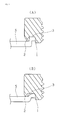
- Fig. 1 is a sectional view illustrating the foregoing state.
- (A) shows the case of an ordinary steel plate
- (B) shows the case of a high-strength steel plate.
- the steel plate S plastically flows into an annular groove 3 between the piercing portion 1 and the outer peripheral projection 2 such that the pierce nut is securely fixed to the steel plate S.
- the inner peripheral surface of the outer peripheral projection 2 forms a sloping surface decreasing in diameter toward the leading end thereof.
- the leading end refers to the direction in which the end is further away from the nut body in the axial direction thereof.
- a pierce nut for a high-strength steel plate is disclosed in Patent Document 1.
- the pierce nut for a high-strength steel plate does not include a conventional outer peripheral projection 2.
- this pierce nut has an outer groove, an annular projection, and an inner groove in order to enhance the contact between the high-strength steel plate and the pierce nut, thereby ensuring rotation torque.
- complete elimination of the outer peripheral projection 2 may lead to a decrease in peeling strength of the pierce nut from the steel plate.
- the invention to solve the foregoing invention provides a pierce nut used for a high-strength steel plate.
- the pierce nut includes a female screw thread portion formed in the center of a nut body, an annular piercing portion projecting round the female thread portion, and an annular outer peripheral projection extending from the periphery of the nut body.
- the outer periphery of the piercing portion forms a first sloping surface increasing in diameter toward the leading end thereof, and also the inner peripheral surface of the outer peripheral projection forms a second sloping surface increasing in diameter toward the leading end thereof. Serrations are formed on the second sloping surface.
- the central angle of the second sloping angle be greater than the central angle of the first sloping surface.
- the inner peripheral surface of the piercing portion form a third sloping surface increasing in diameter toward the leading end thereof.
- the outer peripheral surface of a piercing portion forms a first sloping surface
- the inner peripheral surface of an outer peripheral projection forms a second sloping surface increasing in diameter toward the leading end thereof, and an annular groove is formed between these sloping surfaces.
- the pierce nut according the invention is configured such that the corresponding inner peripheral surface forms a sloping surface increasing in diameter toward the leading end thereof.
- the outer peripheral edge portion of the steel plate which has flowed into the annular groove, comes into secure contact with the inner periphery of the outer peripheral projection.
- this inner periphery has serrations, sufficient rotation torque can be ensured.
- the outer peripheral projection has a trapezoidal sectional shape in which the dimension on the nut body side is wide, thus increasing rigidity and preventing conventional deformation.
- a pierce nut for a high-strength steel plate according to the invention can also be used for a high-strength steel plate for which a conventional pierce nut cannot be used.
- a pierce nut according to the invention can also be used for a conventional low-strength steel plate.
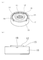
- Figs. 2 to 4 show a pierce nut for a high-strength steel plate.
- the reference 10 represents a nut body in a short cylindrical form; 11, a female screw thread portion formed in the center of the nut body; 12, an annular piercing portion formed on the outer periphery of the female screw thread portion 11; 13, an annular outer peripheral projection extending from the outer periphery of the nut body 10; 14, an annular groove formed between the piercing portion 12 and outer peripheral projection 13.
- the height of the projection of the piercing portion 12 is greater than that of the outer peripheral projection 13.
- the nut body 10 is submitted to hardening treatment such as heat treatment.
- the outer peripheral surface of the piercing portion 12 forms a first slanting surface 15 increasing in diameter toward the leading end thereof. Its central angle ⁇ 1 is about 10° to 30°. Additionally, the inner peripheral surface of the outer peripheral projection 13 forms a second slanting surface 16 increasing in diameter toward the leading end thereof. Its central angle ⁇ 2 is, in this embodiment, 60°. However, it can vary according to the strength of the high-strength steel plate, which is a mating member. Specifically, where the strength is higher, the central angle ⁇ 2 is made greater than 60° and, where the strength is lower, the central angle ⁇ 2 is made less than 60°. The preferable range of the central angle ⁇ 2 for the second sloping surface 16 is 40° to 80°.
- the central angle ⁇ 2 of the second sloping surface 16 is greater than the central angle ⁇ 1 of the first sloping surface 15. Accordingly, the annular groove 14 formed between them has a sectional shape in which the leading end side of the annular groove 14 is wider than its bottom, which is located on the same side as the nut body 10. Accordingly, a steel plate is able to flow into the groove.
- serrations 17 are formed on the second sloping surface 16.
- the serrations 17 are provided by forming mountain-shaped projections all the way around the second sloping surface 16.
- the serrations 17 dig into the steel plate that has flowed into the annular groove 14 and thus sufficient rotation torque can be obtained.
- the shape of the serrations 17 can be variously modified, and the number thereof is not limited by this embodiment either.
- four grooves 18 are formed in the end face of the outer peripheral projection 13. However, they are not the principal part of this invention and can be omitted.
- the inner peripheral surface of the piercing portion 12 forms a third sloping surface 19 increasing in diameter toward the leading end thereof.
- the third sloping surface 19 functions as a guide to the female screw thread portion 11.
- the pierce nut according to the invention which is thus configured, is used for a high-strength steel plate and is driven thereinto by means of a punch in the same manner as with a conventional nut.
- the piercing portion 12 runs through the steel plate, which is a mating member, making a circular hole in it, and simultaneously allows a plastic flow of the steel plate around the circular hole, such that the steel plate is brought into secure contact with the inside of the annular groove 14, as shown in Fig. 5 .
- the inner peripheral surface of the outer peripheral projection 13 forms the second sloping surface 16 increasing in diameter toward the leading end thereof.
- the outer peripheral projection 13 has a trapezoidal section of which the dimension on the same side as the nut body 10 is wide. Accordingly, even when the piercing portion 12 is driven into a high-strength steel plate, the outer peripheral projection 13 is prevented from being deformed as in a conventional one.
- the steel plate that has flowed into the annular groove 14 is in secure contact with the first sloping surface 15 increasing in diameter toward the leading end thereof, thus making it possible to ensure the strength of the pierce nut against axial separation. If load to separate the pierce nut body 10 from the steel plate is applied, stress to flatten out the steel plate that has flowed into the annular groove 14 may be produced. However, the outer periphery of the steel plate that has flowed into the annular groove 14 is restricted by the inner peripheral surface of the outer peripheral projection 13 and, moreover, the high-strength steel plate is less likely to deform. Accordingly, the pierce nut is able to withstand the load that would separate the pierce nut.
- the value of peeling strength was obtained in the following manner: a pierce nut to be tested, which had been driven into a steel plate, was set on a jig with a central hole formed in it, a bolt was screwed into the pierce nut, pressure was applied vertically downward to the bolt by a compression testing machine, and the load at which the pierce nut was separated from the steel plate was measured.
- the rotation torque value was obtained in the following manner: a bolt was screwed into a pierce nut to be tested, which had been driven into a steel plate, then, using a torque wrench with a socket attached thereto, the head of the bolt was rotated in tightening direction, and torque at which the pierce nut was separated from the steel plate was measured.
- the pierce nut for a high-strength steel plate according to the invention has an advantageous effect that, even where a mating member is a high-strength steel plate, the pierce nut can ensure the same peeling strength and rotation torque as with a conventional nut, without deformation of the pierce nut itself.
Landscapes
- Engineering & Computer Science (AREA)
- General Engineering & Computer Science (AREA)
- Mechanical Engineering (AREA)
- Connection Of Plates (AREA)
Applications Claiming Priority (2)
| Application Number | Priority Date | Filing Date | Title |
|---|---|---|---|
| JP2012186014A JP6123082B2 (ja) | 2012-08-27 | 2012-08-27 | 高強度鋼板用ピアスナット |
| PCT/JP2013/065454 WO2014034211A1 (fr) | 2012-08-27 | 2013-06-04 | Écrou de perçage pour tôle d'acier à haute résistance |
Publications (3)
| Publication Number | Publication Date |
|---|---|
| EP2787221A1 true EP2787221A1 (fr) | 2014-10-08 |
| EP2787221A4 EP2787221A4 (fr) | 2015-09-09 |
| EP2787221B1 EP2787221B1 (fr) | 2017-08-02 |
Family
ID=50183036
Family Applications (1)
| Application Number | Title | Priority Date | Filing Date |
|---|---|---|---|
| EP13832172.4A Active EP2787221B1 (fr) | 2012-08-27 | 2013-06-04 | Écrou de perçage pour tôle d'acier à haute résistance |
Country Status (5)
| Country | Link |
|---|---|
| US (1) | US9328762B2 (fr) |
| EP (1) | EP2787221B1 (fr) |
| JP (1) | JP6123082B2 (fr) |
| CN (1) | CN104024662B (fr) |
| WO (1) | WO2014034211A1 (fr) |
Families Citing this family (10)
| Publication number | Priority date | Publication date | Assignee | Title |
|---|---|---|---|---|
| CN105805137A (zh) * | 2016-05-31 | 2016-07-27 | 常州市耐斯工控工程有限公司 | 滤水型螺母 |
| CN107061468B (zh) * | 2017-04-13 | 2021-01-15 | 宾科精密部件(中国)有限公司 | 一种防水压铆螺母 |
| JP6732389B2 (ja) * | 2018-01-25 | 2020-07-29 | 株式会社青山製作所 | 板材へのナットとカラーの取付方法及び取付構造 |
| JP7073180B2 (ja) * | 2018-04-17 | 2022-05-23 | ボーセイキャプティブ株式会社 | かしめナット及びかしめナットの冷間圧造方法 |
| JPWO2020261684A1 (fr) * | 2019-06-28 | 2020-12-30 | ||
| DE102019120894A1 (de) * | 2019-08-02 | 2021-02-04 | SF Handels- und Besitzgesellschaft mbH | Sicherungsmutter |
| DE102020111696A1 (de) * | 2020-04-29 | 2021-11-04 | Profil Verbindungstechnik Gmbh & Co. Kg | Funktionselement |
| DE112021000063T5 (de) | 2020-06-30 | 2022-03-24 | Aoyama Seisakusho Co., Ltd. | Stanzmutter und verfahren zum fixieren davon an einer innenfläche eines gegenstücks mit geschlossener querschnittsform |
| US12163548B2 (en) * | 2022-08-26 | 2024-12-10 | Rb&W Manufacturing Llc | Self-clinching fastener |
| DE102022128974A1 (de) * | 2022-11-02 | 2024-05-02 | Bayerische Motoren Werke Aktiengesellschaft | Verfahren zur Herstellung eines pressgehärteten Blechformteils mit einem Einpresselement und pressgehärtetes Blechformteil mit einem Einpresselement |
Family Cites Families (9)
| Publication number | Priority date | Publication date | Assignee | Title |
|---|---|---|---|---|
| US3253631A (en) * | 1963-06-17 | 1966-05-31 | Republic Steel Corp | Cold-formed self-piercing nut |
| JPS6458807A (en) * | 1987-08-27 | 1989-03-06 | Shinjo Seisakusho Kk | Pierce nut |
| JPH0328514A (ja) * | 1989-04-27 | 1991-02-06 | Iwata Booruto Kogyo Kk | クリンチナット及びその取付方法 |
| JPH05202917A (ja) * | 1992-01-28 | 1993-08-10 | Aoyama Seisakusho:Kk | ピアスナット |
| JPH11193808A (ja) * | 1998-01-06 | 1999-07-21 | Aoyama Seisakusho Co Ltd | ピアスナット |
| JP2005240836A (ja) * | 2004-02-24 | 2005-09-08 | Shinjo Mfg Co Ltd | 厚板用ピアスナット |
| DE102004017866A1 (de) * | 2004-04-13 | 2005-11-03 | Profil-Verbindungstechnik Gmbh & Co. Kg | Verfahren zur Herstellung von Hohlkörperelementen, Hohlkörperelement, Zusammenbauteil sowie Folgeverbundwerkzeug zur Durchführung des Verfahrens |
| US7740436B2 (en) * | 2006-03-22 | 2010-06-22 | R B & W Manufacturing Llc | Clinch nut |
| SE530092C2 (sv) * | 2006-04-25 | 2008-02-26 | Stroemsholmen Ab | Stansmutter samt användning därav och system innefattande en sådan stansmutter |
-
2012
- 2012-08-27 JP JP2012186014A patent/JP6123082B2/ja active Active
-
2013
- 2013-06-04 WO PCT/JP2013/065454 patent/WO2014034211A1/fr not_active Ceased
- 2013-06-04 EP EP13832172.4A patent/EP2787221B1/fr active Active
- 2013-06-04 CN CN201380004687.XA patent/CN104024662B/zh active Active
-
2014
- 2014-05-15 US US14/278,412 patent/US9328762B2/en active Active
Also Published As
| Publication number | Publication date |
|---|---|
| US9328762B2 (en) | 2016-05-03 |
| US20140248104A1 (en) | 2014-09-04 |
| CN104024662A (zh) | 2014-09-03 |
| JP2014043883A (ja) | 2014-03-13 |
| EP2787221B1 (fr) | 2017-08-02 |
| WO2014034211A1 (fr) | 2014-03-06 |
| JP6123082B2 (ja) | 2017-05-10 |
| EP2787221A4 (fr) | 2015-09-09 |
| CN104024662B (zh) | 2017-07-28 |
Similar Documents
| Publication | Publication Date | Title |
|---|---|---|
| US9328762B2 (en) | Pierce nut for high-strength steel plate | |
| US9322424B2 (en) | Nut with lug flare | |
| US8931990B2 (en) | Pierce nut and use thereof | |
| JP3781057B2 (ja) | リベッティング可能な要素、組立体、組立方法及びリベッティングダイ | |
| US11028868B2 (en) | Press-fit connection between a high-strength component and a press-fit element, method for making such a press-fit connection, and press-fit element for such a press-fit connection | |
| US20160230800A1 (en) | Part fitted with fastening member, and method of attaching the same | |
| US8221040B2 (en) | Component assembly consisting of a fastener element and a sheet metal part and also a method for manufacturing such a component assembly | |
| US8141229B2 (en) | Element attachable by riveting to a sheet metal part and also a component assembly and a method for the production of the component assembly | |
| US9175715B2 (en) | Functional element having features providing security against rotation and also a component assembly consisting of the functional element and a sheet metal part | |
| JP6214696B2 (ja) | かしめボルト | |
| CN108884854B (zh) | 自冲式压入元件、压入连接部和用于制造这种压入连接部的方法 | |
| US11209040B2 (en) | Self-clinching fastener | |
| US20120003059A1 (en) | Clinch bolt | |
| CN101438066B (zh) | 冲孔螺母及其用途 | |
| US11326640B2 (en) | Fastening element | |
| WO2021010959A1 (fr) | Élément de fixation autobloquant | |
| US9752609B2 (en) | Threaded fastener | |
| JP2014202226A (ja) | フランジナット | |
| JP4198724B2 (ja) | ねじの緩み止め構造 | |
| US10155481B2 (en) | Integrated fastener for plastic automotive components |
Legal Events
| Date | Code | Title | Description |
|---|---|---|---|
| PUAI | Public reference made under article 153(3) epc to a published international application that has entered the european phase |
Free format text: ORIGINAL CODE: 0009012 |
|
| 17P | Request for examination filed |
Effective date: 20140610 |
|
| AK | Designated contracting states |
Kind code of ref document: A1 Designated state(s): AL AT BE BG CH CY CZ DE DK EE ES FI FR GB GR HR HU IE IS IT LI LT LU LV MC MK MT NL NO PL PT RO RS SE SI SK SM TR |
|
| RA4 | Supplementary search report drawn up and despatched (corrected) |
Effective date: 20150810 |
|
| RIC1 | Information provided on ipc code assigned before grant |
Ipc: F16B 37/06 20060101ALI20150804BHEP Ipc: F16B 37/04 20060101AFI20150804BHEP |
|
| DAX | Request for extension of the european patent (deleted) | ||
| GRAP | Despatch of communication of intention to grant a patent |
Free format text: ORIGINAL CODE: EPIDOSNIGR1 |
|
| INTG | Intention to grant announced |
Effective date: 20170309 |
|
| GRAS | Grant fee paid |
Free format text: ORIGINAL CODE: EPIDOSNIGR3 |
|
| GRAA | (expected) grant |
Free format text: ORIGINAL CODE: 0009210 |
|
| AK | Designated contracting states |
Kind code of ref document: B1 Designated state(s): AL AT BE BG CH CY CZ DE DK EE ES FI FR GB GR HR HU IE IS IT LI LT LU LV MC MK MT NL NO PL PT RO RS SE SI SK SM TR |
|
| REG | Reference to a national code |
Ref country code: CH Ref legal event code: EP Ref country code: AT Ref legal event code: REF Ref document number: 914824 Country of ref document: AT Kind code of ref document: T Effective date: 20170815 |
|
| REG | Reference to a national code |
Ref country code: IE Ref legal event code: FG4D |
|
| REG | Reference to a national code |
Ref country code: DE Ref legal event code: R096 Ref document number: 602013024545 Country of ref document: DE |
|
| REG | Reference to a national code |
Ref country code: SE Ref legal event code: TRGR |
|
| REG | Reference to a national code |
Ref country code: NL Ref legal event code: MP Effective date: 20170802 |
|
| REG | Reference to a national code |
Ref country code: AT Ref legal event code: MK05 Ref document number: 914824 Country of ref document: AT Kind code of ref document: T Effective date: 20170802 |
|
| REG | Reference to a national code |
Ref country code: LT Ref legal event code: MG4D |
|
| PG25 | Lapsed in a contracting state [announced via postgrant information from national office to epo] |
Ref country code: NL Free format text: LAPSE BECAUSE OF FAILURE TO SUBMIT A TRANSLATION OF THE DESCRIPTION OR TO PAY THE FEE WITHIN THE PRESCRIBED TIME-LIMIT Effective date: 20170802 Ref country code: AT Free format text: LAPSE BECAUSE OF FAILURE TO SUBMIT A TRANSLATION OF THE DESCRIPTION OR TO PAY THE FEE WITHIN THE PRESCRIBED TIME-LIMIT Effective date: 20170802 Ref country code: NO Free format text: LAPSE BECAUSE OF FAILURE TO SUBMIT A TRANSLATION OF THE DESCRIPTION OR TO PAY THE FEE WITHIN THE PRESCRIBED TIME-LIMIT Effective date: 20171102 Ref country code: FI Free format text: LAPSE BECAUSE OF FAILURE TO SUBMIT A TRANSLATION OF THE DESCRIPTION OR TO PAY THE FEE WITHIN THE PRESCRIBED TIME-LIMIT Effective date: 20170802 Ref country code: LT Free format text: LAPSE BECAUSE OF FAILURE TO SUBMIT A TRANSLATION OF THE DESCRIPTION OR TO PAY THE FEE WITHIN THE PRESCRIBED TIME-LIMIT Effective date: 20170802 Ref country code: HR Free format text: LAPSE BECAUSE OF FAILURE TO SUBMIT A TRANSLATION OF THE DESCRIPTION OR TO PAY THE FEE WITHIN THE PRESCRIBED TIME-LIMIT Effective date: 20170802 |
|
| PG25 | Lapsed in a contracting state [announced via postgrant information from national office to epo] |
Ref country code: RS Free format text: LAPSE BECAUSE OF FAILURE TO SUBMIT A TRANSLATION OF THE DESCRIPTION OR TO PAY THE FEE WITHIN THE PRESCRIBED TIME-LIMIT Effective date: 20170802 Ref country code: GR Free format text: LAPSE BECAUSE OF FAILURE TO SUBMIT A TRANSLATION OF THE DESCRIPTION OR TO PAY THE FEE WITHIN THE PRESCRIBED TIME-LIMIT Effective date: 20171103 Ref country code: LV Free format text: LAPSE BECAUSE OF FAILURE TO SUBMIT A TRANSLATION OF THE DESCRIPTION OR TO PAY THE FEE WITHIN THE PRESCRIBED TIME-LIMIT Effective date: 20170802 Ref country code: PL Free format text: LAPSE BECAUSE OF FAILURE TO SUBMIT A TRANSLATION OF THE DESCRIPTION OR TO PAY THE FEE WITHIN THE PRESCRIBED TIME-LIMIT Effective date: 20170802 Ref country code: IS Free format text: LAPSE BECAUSE OF FAILURE TO SUBMIT A TRANSLATION OF THE DESCRIPTION OR TO PAY THE FEE WITHIN THE PRESCRIBED TIME-LIMIT Effective date: 20171202 Ref country code: BG Free format text: LAPSE BECAUSE OF FAILURE TO SUBMIT A TRANSLATION OF THE DESCRIPTION OR TO PAY THE FEE WITHIN THE PRESCRIBED TIME-LIMIT Effective date: 20171102 Ref country code: ES Free format text: LAPSE BECAUSE OF FAILURE TO SUBMIT A TRANSLATION OF THE DESCRIPTION OR TO PAY THE FEE WITHIN THE PRESCRIBED TIME-LIMIT Effective date: 20170802 |
|
| PG25 | Lapsed in a contracting state [announced via postgrant information from national office to epo] |
Ref country code: RO Free format text: LAPSE BECAUSE OF FAILURE TO SUBMIT A TRANSLATION OF THE DESCRIPTION OR TO PAY THE FEE WITHIN THE PRESCRIBED TIME-LIMIT Effective date: 20170802 Ref country code: DK Free format text: LAPSE BECAUSE OF FAILURE TO SUBMIT A TRANSLATION OF THE DESCRIPTION OR TO PAY THE FEE WITHIN THE PRESCRIBED TIME-LIMIT Effective date: 20170802 Ref country code: CZ Free format text: LAPSE BECAUSE OF FAILURE TO SUBMIT A TRANSLATION OF THE DESCRIPTION OR TO PAY THE FEE WITHIN THE PRESCRIBED TIME-LIMIT Effective date: 20170802 |
|
| REG | Reference to a national code |
Ref country code: DE Ref legal event code: R097 Ref document number: 602013024545 Country of ref document: DE |
|
| PG25 | Lapsed in a contracting state [announced via postgrant information from national office to epo] |
Ref country code: IT Free format text: LAPSE BECAUSE OF FAILURE TO SUBMIT A TRANSLATION OF THE DESCRIPTION OR TO PAY THE FEE WITHIN THE PRESCRIBED TIME-LIMIT Effective date: 20170802 Ref country code: SK Free format text: LAPSE BECAUSE OF FAILURE TO SUBMIT A TRANSLATION OF THE DESCRIPTION OR TO PAY THE FEE WITHIN THE PRESCRIBED TIME-LIMIT Effective date: 20170802 Ref country code: EE Free format text: LAPSE BECAUSE OF FAILURE TO SUBMIT A TRANSLATION OF THE DESCRIPTION OR TO PAY THE FEE WITHIN THE PRESCRIBED TIME-LIMIT Effective date: 20170802 Ref country code: SM Free format text: LAPSE BECAUSE OF FAILURE TO SUBMIT A TRANSLATION OF THE DESCRIPTION OR TO PAY THE FEE WITHIN THE PRESCRIBED TIME-LIMIT Effective date: 20170802 |
|
| PLBE | No opposition filed within time limit |
Free format text: ORIGINAL CODE: 0009261 |
|
| STAA | Information on the status of an ep patent application or granted ep patent |
Free format text: STATUS: NO OPPOSITION FILED WITHIN TIME LIMIT |
|
| 26N | No opposition filed |
Effective date: 20180503 |
|
| PG25 | Lapsed in a contracting state [announced via postgrant information from national office to epo] |
Ref country code: SI Free format text: LAPSE BECAUSE OF FAILURE TO SUBMIT A TRANSLATION OF THE DESCRIPTION OR TO PAY THE FEE WITHIN THE PRESCRIBED TIME-LIMIT Effective date: 20170802 |
|
| REG | Reference to a national code |
Ref country code: CH Ref legal event code: PL |
|
| GBPC | Gb: european patent ceased through non-payment of renewal fee |
Effective date: 20180604 |
|
| REG | Reference to a national code |
Ref country code: BE Ref legal event code: MM Effective date: 20180630 |
|
| REG | Reference to a national code |
Ref country code: IE Ref legal event code: MM4A |
|
| PG25 | Lapsed in a contracting state [announced via postgrant information from national office to epo] |
Ref country code: MC Free format text: LAPSE BECAUSE OF FAILURE TO SUBMIT A TRANSLATION OF THE DESCRIPTION OR TO PAY THE FEE WITHIN THE PRESCRIBED TIME-LIMIT Effective date: 20170802 Ref country code: LU Free format text: LAPSE BECAUSE OF NON-PAYMENT OF DUE FEES Effective date: 20180604 |
|
| PG25 | Lapsed in a contracting state [announced via postgrant information from national office to epo] |
Ref country code: LI Free format text: LAPSE BECAUSE OF NON-PAYMENT OF DUE FEES Effective date: 20180630 Ref country code: FR Free format text: LAPSE BECAUSE OF NON-PAYMENT OF DUE FEES Effective date: 20180630 Ref country code: IE Free format text: LAPSE BECAUSE OF NON-PAYMENT OF DUE FEES Effective date: 20180604 Ref country code: GB Free format text: LAPSE BECAUSE OF NON-PAYMENT OF DUE FEES Effective date: 20180604 Ref country code: CH Free format text: LAPSE BECAUSE OF NON-PAYMENT OF DUE FEES Effective date: 20180630 |
|
| PG25 | Lapsed in a contracting state [announced via postgrant information from national office to epo] |
Ref country code: BE Free format text: LAPSE BECAUSE OF NON-PAYMENT OF DUE FEES Effective date: 20180630 |
|
| PG25 | Lapsed in a contracting state [announced via postgrant information from national office to epo] |
Ref country code: MT Free format text: LAPSE BECAUSE OF NON-PAYMENT OF DUE FEES Effective date: 20180604 |
|
| PG25 | Lapsed in a contracting state [announced via postgrant information from national office to epo] |
Ref country code: TR Free format text: LAPSE BECAUSE OF FAILURE TO SUBMIT A TRANSLATION OF THE DESCRIPTION OR TO PAY THE FEE WITHIN THE PRESCRIBED TIME-LIMIT Effective date: 20170802 |
|
| PG25 | Lapsed in a contracting state [announced via postgrant information from national office to epo] |
Ref country code: PT Free format text: LAPSE BECAUSE OF FAILURE TO SUBMIT A TRANSLATION OF THE DESCRIPTION OR TO PAY THE FEE WITHIN THE PRESCRIBED TIME-LIMIT Effective date: 20170802 Ref country code: HU Free format text: LAPSE BECAUSE OF FAILURE TO SUBMIT A TRANSLATION OF THE DESCRIPTION OR TO PAY THE FEE WITHIN THE PRESCRIBED TIME-LIMIT; INVALID AB INITIO Effective date: 20130604 |
|
| PG25 | Lapsed in a contracting state [announced via postgrant information from national office to epo] |
Ref country code: CY Free format text: LAPSE BECAUSE OF FAILURE TO SUBMIT A TRANSLATION OF THE DESCRIPTION OR TO PAY THE FEE WITHIN THE PRESCRIBED TIME-LIMIT Effective date: 20170802 Ref country code: MK Free format text: LAPSE BECAUSE OF NON-PAYMENT OF DUE FEES Effective date: 20170802 |
|
| PG25 | Lapsed in a contracting state [announced via postgrant information from national office to epo] |
Ref country code: AL Free format text: LAPSE BECAUSE OF FAILURE TO SUBMIT A TRANSLATION OF THE DESCRIPTION OR TO PAY THE FEE WITHIN THE PRESCRIBED TIME-LIMIT Effective date: 20170802 |
|
| PGFP | Annual fee paid to national office [announced via postgrant information from national office to epo] |
Ref country code: DE Payment date: 20250523 Year of fee payment: 13 |
|
| PGFP | Annual fee paid to national office [announced via postgrant information from national office to epo] |
Ref country code: SE Payment date: 20250523 Year of fee payment: 13 |