EP2787261A1 - In einer Flüssigkeitsverteilungsnetz integriertes Ventil, Netz und Energieumwandlungsinstallation mit solch einem Ventil - Google Patents
In einer Flüssigkeitsverteilungsnetz integriertes Ventil, Netz und Energieumwandlungsinstallation mit solch einem Ventil Download PDFInfo
- Publication number
- EP2787261A1 EP2787261A1 EP14163221.6A EP14163221A EP2787261A1 EP 2787261 A1 EP2787261 A1 EP 2787261A1 EP 14163221 A EP14163221 A EP 14163221A EP 2787261 A1 EP2787261 A1 EP 2787261A1
- Authority
- EP
- European Patent Office
- Prior art keywords
- valve
- ring
- shut
- fluid
- screw
- Prior art date
- Legal status (The legal status is an assumption and is not a legal conclusion. Google has not performed a legal analysis and makes no representation as to the accuracy of the status listed.)
- Granted
Links
- 239000012530 fluid Substances 0.000 title claims description 39
- 238000009434 installation Methods 0.000 title claims description 12
- 238000006243 chemical reaction Methods 0.000 title 1
- 230000007246 mechanism Effects 0.000 claims description 55
- 238000007789 sealing Methods 0.000 claims description 55
- 238000012423 maintenance Methods 0.000 claims description 53
- 238000011144 upstream manufacturing Methods 0.000 claims description 24
- 239000012528 membrane Substances 0.000 claims description 14
- 230000003100 immobilizing effect Effects 0.000 claims description 13
- 238000000034 method Methods 0.000 claims description 4
- 230000000295 complement effect Effects 0.000 description 5
- 210000002105 tongue Anatomy 0.000 description 3
- 229910000831 Steel Inorganic materials 0.000 description 2
- 229920001971 elastomer Polymers 0.000 description 2
- 239000000806 elastomer Substances 0.000 description 2
- 238000002347 injection Methods 0.000 description 2
- 239000007924 injection Substances 0.000 description 2
- 239000002184 metal Substances 0.000 description 2
- 239000007769 metal material Substances 0.000 description 2
- 239000010959 steel Substances 0.000 description 2
- XLYOFNOQVPJJNP-UHFFFAOYSA-N water Substances O XLYOFNOQVPJJNP-UHFFFAOYSA-N 0.000 description 2
- 230000009471 action Effects 0.000 description 1
- 229910000963 austenitic stainless steel Inorganic materials 0.000 description 1
- 230000006835 compression Effects 0.000 description 1
- 238000007906 compression Methods 0.000 description 1
- 230000000694 effects Effects 0.000 description 1
- 230000005611 electricity Effects 0.000 description 1
- 230000001939 inductive effect Effects 0.000 description 1
- 230000003993 interaction Effects 0.000 description 1
- 230000008531 maintenance mechanism Effects 0.000 description 1
- 230000007257 malfunction Effects 0.000 description 1
- 238000004519 manufacturing process Methods 0.000 description 1
- 229910001105 martensitic stainless steel Inorganic materials 0.000 description 1
- 239000000463 material Substances 0.000 description 1
- 230000008439 repair process Effects 0.000 description 1
- 230000002441 reversible effect Effects 0.000 description 1
Images






Classifications
-
- F—MECHANICAL ENGINEERING; LIGHTING; HEATING; WEAPONS; BLASTING
- F16—ENGINEERING ELEMENTS AND UNITS; GENERAL MEASURES FOR PRODUCING AND MAINTAINING EFFECTIVE FUNCTIONING OF MACHINES OR INSTALLATIONS; THERMAL INSULATION IN GENERAL
- F16K—VALVES; TAPS; COCKS; ACTUATING-FLOATS; DEVICES FOR VENTING OR AERATING
- F16K1/00—Lift valves or globe valves, i.e. cut-off apparatus with closure members having at least a component of their opening and closing motion perpendicular to the closing faces
- F16K1/16—Lift valves or globe valves, i.e. cut-off apparatus with closure members having at least a component of their opening and closing motion perpendicular to the closing faces with pivoted closure-members
- F16K1/18—Lift valves or globe valves, i.e. cut-off apparatus with closure members having at least a component of their opening and closing motion perpendicular to the closing faces with pivoted closure-members with pivoted discs or flaps
- F16K1/22—Lift valves or globe valves, i.e. cut-off apparatus with closure members having at least a component of their opening and closing motion perpendicular to the closing faces with pivoted closure-members with pivoted discs or flaps with axis of rotation crossing the valve member, e.g. butterfly valves
- F16K1/226—Shaping or arrangements of the sealing
- F16K1/228—Movable sealing bodies
-
- F—MECHANICAL ENGINEERING; LIGHTING; HEATING; WEAPONS; BLASTING
- F16—ENGINEERING ELEMENTS AND UNITS; GENERAL MEASURES FOR PRODUCING AND MAINTAINING EFFECTIVE FUNCTIONING OF MACHINES OR INSTALLATIONS; THERMAL INSULATION IN GENERAL
- F16K—VALVES; TAPS; COCKS; ACTUATING-FLOATS; DEVICES FOR VENTING OR AERATING
- F16K43/00—Auxiliary closure means in valves, which in case of repair, e.g. rewashering, of the valve, can take over the function of the normal closure means; Devices for temporary replacement of parts of valves for the same purpose
Definitions
- the present invention relates to a valve which is integrated, in the use configuration, into a fluid distribution network, in particular upstream of a hydraulic machine, and makes it possible, in a controlled manner, to interrupt or authorize the flow of a fluid in a pipe.
- a hydraulic machine is understood to be a turbine, a pump or a turbine-pump.
- Such a valve comprises a shut-off member which is rotated by a control device of the valve so as to alternately block or authorize the passage of the fluid.
- the invention is applicable particularly in the field of valves of the butterfly type that are used upstream of a hydraulic machine.
- a hydraulic installation may comprise a number of hydraulic machines that are all supplied in parallel by an upstream pipe.
- a valve in order for example to replace the service seal of the valve, it is necessary to work on the valve in the dry state, that is to say without fluid inside.
- This has the drawback that it is necessary to stop the inlet of fluid, upstream of the valve, into the pipe, and thus to cease supplying the other hydraulic machines of the installation.
- This is particularly disadvantageous from an economical point of view, since the production or the distribution of the fluid is stopped during maintenance operations on the valves.
- a maintenance sealing mechanism the function of which is to seal the valve when a maintenance operation is carried out on the service seal.
- the maintenance sealing mechanism is thus positioned upstream of the service seal.
- the maintenance mechanism is, in this case, simply a seal having a profile in the form of a musical note, the round part of which is pressed radially against the shut-off member around the entire periphery of the latter by virtue of rods that are manipulated outside the valve.
- This mechanism is generally satisfactory.
- the seal is made of an elastomer material which does not make it as robust as a mechanism that uses metallic parts.
- a maintenance sealing mechanism composed of a metal ring that is able to move and has a conical internal surface which is complementary to the external surface of the shut-off member which it surrounds and which, in a controlled manner, is pressed against the latter in order to provide sealing during a maintenance operation.
- the use of a metal ring provides greater resistance to the pressure of the fluid inside the valve.
- a seal is disposed in a groove outside the valve and is compressed during contact between the ring and the shut-off member. This makes it possible to seal the assembly.
- shut-off member the external surface of the shut-off member will be complementary with the internal surface of the ring.
- the ring does not adapt correctly to all types of shut-off member.
- valves that comprise two shut-off members.
- a mobile ring bearing against the upstream shut-off member, compresses a seal made of elastomer.
- a valve having two shut-off members involves a greater head loss than a valve having a single shut-off member. This is because, when the shut-off member is in the open position, it nevertheless resists the passage of the fluid. This additional head loss results in a weaker jet power at the outlet of the pipe.
- maintenance sealing mechanisms comprising a flexible tongue made of metal material, in particular steel, which is pressed against the shut-off member in order to provide sealing are known from US-A-4 898 363 , US-A-3 834 663 and US-A-4 037 819 .
- the drawback of these mechanisms is that it is difficult to adapt the geometry of the tongue to that of the shut-off member, this making them poorly adaptable to different types of valve.
- they are only applicable for valves having small dimensions, in particular for a diameter of between 200 and 300 mm. Specifically, it is to be feared that, for valves having a diameter of between 1 and 8 m, these flexible tongues made of steel do not provide sufficient resistance to the pressure of the upstream fluid.
- the invention relates to a valve which is integrated into a fluid distribution network and makes it possible, in a selective manner, to interrupt or authorize the flow of a fluid in an axial direction of a pipe, this valve comprising an external body, inside which a shut-off member is disposed, a service seal which, in a shut-off position of the valve, provides sealing between the shut-off member and the body of the valve, and a maintenance sealing mechanism which is disposed upstream of the service seal and which provides sealing during maintenance operations on the service seal.
- This mechanism comprises a ring which is able to move axially, with respect to the body of the valve, between a retracted position, in which it does not prevent the passage of the fluid, and a forward position, where it bears in a sealing manner against the shut-off member.
- the ring carries, on its internal surface, an elastically deformable membrane which, when the ring is in the forward position, bears, at least partially, against the shut-off member.
- the sealing of the valve during maintenance operations is improved and the maintenance sealing mechanism resists a high pressure inside the valve and is adaptable to different valves.
- a valve may incorporate one or more of the following features in any technically admissible combination:
- the invention also relates to a fluid distribution network comprising at least one valve as described above, installed on a pipe.
- the invention also relates to an installation for converting hydraulic energy into electrical or mechanical energy, or vice versa, comprising a fluid distribution network as mentioned above, wherein the pipe is a supply pipe of a hydraulic machine belonging to the installation.
- the invention relates to a method for carrying out a maintenance operation on a service seal and/or on a downstream liner of a valve as described above, characterized in that it comprises at least the following steps of:
- the method may also comprise, for a valve which comprises a device for immobilizing the ring, a step, following step a) and preceding step b), that consists in manipulating the immobilizing device on the valve so as to insert the end of each locking rod radially between the ring and the annular frame.
- FIG. 1 shows an example of an installation 1 for converting hydraulic energy into electrical energy according to the invention, this hydraulic installation 1 comprising a dam B, an upstream pond R1, a plurality of hydraulic machines M1 and M2 and a downstream pond R2.
- This type of hydraulic installation makes it possible, inter alia, to store electrical energy in a simple manner: it is conceivable for each hydraulic machine to function as a turbine during the day, that is to say to use hydraulic energy resulting from the difference in height h between the upstream pond R1 and the hydraulic machine M1 or M2 in order for example to rotate an alternator and thus to produce electricity, and to function as a pump at night, thus conveying the water contained in the downstream pond R2 to the upstream pond R1.
- the hydraulic installation also comprises a supply pipe C which is connected to the upstream pond R1 and which supplies all of the hydraulic machines, in parallel, by means of a bifurcation D located upstream of all the hydraulic machines.
- a first valve 4 known as the pipe head valve, stops or alternatively authorizes the flow in the pipe C.
- a second valve 2, called the guard valve, is located downstream of the bifurcation and upstream of each hydraulic machine. It stops or alternatively supplies the hydraulic machine respectively located downstream of this valve.
- a supply line C1 of the hydraulic machine M1 and a supply line C2 of the hydraulic machine M2 are noted.
- the pipe C and the lines C1 and C2 together form a fluid distribution network.
- the following description thus relates more particularly to a guard valve 2 for authorizing or stopping the supplying of the hydraulic machine M1.
- a pipe head valve 4 to which the invention also applies. All of this is likewise transposable to a fluid distribution network without a hydraulic machine.
- the guard valve 2 is located in a line C1 which directly supplies the hydraulic machine M1 and through which water thus passes in a direction defined by an axis Y-Y. Furthermore defined are an axis Z-Z that is defined as the axis perpendicular to the axis Y-Y in the plane of Figure 1 , the axis Z-Z being vertical, and an axis X-X perpendicular to the axes Y-Y and Z-Z and to the plane of Figure 1 .
- the axes X-X, Y-Y and Z-Z intersect at the center of the valve 2.
- the forward direction is defined as the upstream direction and the rearward direction is defined as the downstream direction.
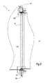
- the valve 2 has a cylindrical overall shape, centered on the axis Y-Y, and comprises an external body 20, inside which a shut-off member 22 is positioned.
- the valve 2 is a butterfly-type valve.
- the shut-off member 22 is a disk and, in the configuration of Figure 2 , the disk 22 is in the shut-off position of the valve 2.
- the valve 2 comprises a service seal 220.
- This seal 220 is disposed in a groove 224 that extends around the entire periphery of the disk 22.
- the service seal 220 seals the valve 2 when the disk 22 is in the shut-off position and the valve is in service.
- the valve 2 likewise comprises a maintenance sealing mechanism M which is disposed upstream of the service seal 220.
- the purpose of this maintenance sealing mechanism M is to seal the valve 2 when it is desired to carry out a maintenance operation on the service seal 220.
- the mechanism M is shown in the retracted position in Figure 4 and in the forward position in Figure 5 .
- This maintenance sealing mechanism M is formed by a plurality of screws 208 and a ring 206. More specifically, the secondary mechanism comprises sixteen screws 208, which are distributed regularly around the central axis Y-Y and which each extend along an axis Y208 parallel to the axis Y-Y.
- These screws 208 are inserted into threads 2040 in an annular frame 204 fixed to the external body 20, in the vicinity of the shut-off member 22 when the latter is in the shut-off position of the valve.
- the annular frame 204 is disposed, radially with respect to the axis Y-Y, around the shut-off member 22 and carries a lining 2042 for supporting the seal 220 in this position.
- the screws 208 each have a threaded part 2082 that has a thread pitch complementary to that of the thread 2040.
- Disposed around each screw 208 and upstream of the thread 2040 into which the latter is inserted is a self-lubricating bush 210 for guiding the screw 208 in rotation and in translation. Each screw 208 bears, upstream, against the ring 206.
- each screw 208 comprises, in the region of its upstream end, a screw head 2080 having a diameter larger than that of the body of the screw.
- This screw head 2080 is inserted into a slot 2060 that extends radially in the ring 206.
- the ring 206 has sixteen slots 2060 which are distributed regularly around the axis Y-Y. The ring 206 is thus secured axially, that is to say along the axis Y208, to each screw 208.
- An axial clearance J1 is defined as the clearance of the screw head 2080 inside the slot 2060. This clearance is measured parallel to the axis Y208 and is greater than 2 mm.
- the clearance J1 between the ring 206 and the screws 208 is such that a deformation of the ring 206 has a limited effect on the screws 208 and, consequently, on the annular frame 204.
- This deformation may be a radial extension or slight twisting about the axis Y-Y.
- These extension and twisting forces are respectively shown in Figure 7 by the arrows F3 and F4. In these two cases, the deformation of the ring 206 exerts a limited force on the screws 208, since the clearance between the screws 208 and the ring 206 authorizes a slight movement of the ring 206.
- the ring 206 is made of a metallic material, in particular austenitic or martensitic stainless steel. Thus, this provides sufficient resistance to the pressure of the fluid inside the valve 2.
- the external body 20 is formed by a downstream flange 200 and a downstream liner 202 that are fixed together by fixing members 212 which, in this example, are screws.
- the external body 20 has an internal volume V20 in which the fluid may flow.
- the downstream liner 202 has sixteen orifices 0202, each aligned with the threads 2040 in the angular frame 204.
- the number of screws 208, of slots 2060, of orifices 0202 and of threads 2040 is identical and is adapted depending on the size of the valve. In this way, it is it possible to insert a tool, such as a socket wrench, into the orifices 0202 in order to access the functional surfaces of the screws 208.
- each screw 208 comprises, in the region of its end opposite the screw head 208, a housing, the walls of which form the functional surfaces of the screw 208 since they are designed to engage with the socket wrench.
- the ring 206 has an internal surface 2062 which is frustoconical and converges in the downstream direction with respect to the axis Y-Y and to the axis Y208 of each screw 208.
- An inclination angle A2062 of the surface 2062 with respect to an axis Y208 is defined. This angle A2062 is in practice between 5° and 20°, preferably close to 12°.
- the screwing of the screw 208 entails, by engagement between the screw head 2080 and the slot 2060 in the ring 206, the axial movement of the ring 206 toward the front and parallel to the axis Y208.
- the ring 206 comes into contact with an outer surface 222 of the shut-off member 22.
- the axial travel, that is to say parallel to the axis Y208, of the movement of the ring 206 in order to pass from the retracted position shown in Figure 4 to the forward position shown in Figure 5 is denoted d1.
- the travel d1 is between 10 and 20 mm depending on the size of the valve. It is precisely this coming into contact of the ring 206 with the shut-off member 22 which makes it possible to seal the valve 2 when the service seal 220 is demounted.
- the ring 206 When the ring 206 has arrived in the forward position, it is subjected to forces associated with the pressure of the upstream fluid since there is no longer a pressure equilibrium between the front and the rear of the ring 206. Specifically, in the retracted position of the ring 206, the fluid is distributed homogeneously around it. There is thus fluid present downstream of the ring which exerts a pressure in the upstream direction. This means that the ring 206 is not subjected to forces associated with the pressure of the fluid.
- the ring 206 carries on its outside a membrane 2064 which is welded, by its two edges 2064A and 2064B, to the upstream and downstream walls of the ring 206.
- the membrane 2064 extends, in a rectilinear manner, along the internal surface 2062 of the ring 206.
- the width and the shape of the membrane 2064 are adapted such that the membrane 2064 deforms in dependence on its interactions with the shut-off member 22.
- An annular volume V2064 present between the internal surface 2062 of the ring 206 and the membrane 2064 is defined.
- This volume V2064 communicates, by way of a plurality of bores 2068 hollowed out at regular intervals in the ring 206, with the internal volume V20 of the valve.
- the fluid flowing inside the pipe arrives at the volume V2064 if the pipe has not been drained.
- This pressure equilibrium makes it possible not only to limit the compression of the membrane 2064 against the ring 206 but also to increase the contact surface area between the ring 206 and the shut-off member 22.
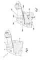
- Figure 6 shows the contact made in a prior art valve R between a mobile ring B and a shut-off member O.
- the contact surface area A between the shut-off member O and the ring B is point-wise in the plane of Figure 6 .
- this has a much greater area than the contact surface area A previously obtained for prior art valves R.
- the outer surface 222 of the shut-off member 22 is inclined in a complementary manner to the internal surface 2062 of the ring 206. This improves sealing, since this is the configuration in which the contact surface area 2064C is largest.
- the maintenance sealing mechanism M comprises a plurality of sensors 214, of the magnetostrictive type, which are inserted into the bores P204 in the annular frame 204 and into housings 0206 in the ring 206, all around the axis Y-Y.
- the sensor 214 has a head 2140 inserted into the ring 206 and is connected, by means of a cable 2142, to a measuring unit (not shown). This sensor 214 makes it possible to measure the forward movement of the ring 206 and thus to know if the maintenance sealing mechanism M is activated or not.
- valve 2 is equipped with sectors 216 which are fixed in the ring 206 by the screws 217. These sectors 216 are self-lubricating sectors which guide the ring 206 in translation along the axis Y-Y with respect to the frame 204.
- FIGS 9 to 12 show a sealing mechanism M' according to a second embodiment of the invention.
- FIG. 9 shows a sealing mechanism M' according to a second embodiment of the invention.
- elements that are different from the first embodiment are described below. Elements having the same structure and having the same function retain their reference while the elements that are different from those in the first embodiment bear the same reference followed by a prime.
- the maintenance sealing mechanism M' differs from that in the first embodiment in that the screws 208' are each secured axially to a collar 2084 which is disposed downstream of the screw head 2080. This collar 2084 is immobilized around each screw 208 and has extensions 2084a that are curved toward the rear. Each screw 208' is likewise secured axially, downstream, to a piston 2086.
- the way in which the mechanism M' functions is described in detail below only for a single screw 208', since it is transposable to all the other screws 208'.
- the maintenance sealing mechanism M' comprises a manual pump, which is not shown in the figures, which supplies circuits 242 and 262 that are respectively connected to the outlet of fittings 24 and 26 and in which the pressure of oil injected does not exceed 650 bar.
- the second fitting 26 is supplied with pressurized oil.
- the second fitting 26 supplies the circuit 262 which communicates with a pulling chamber V2086 disposed between the piston 2086 and the annular frame 204.
- the pressurizing of this pulling chamber V2086 entails a force that pushes the hydraulic cylinder 2086 toward the rear. Since the screw 208' is secured to the hydraulic cylinder 2086, it is likewise moved toward the rear and, by means of the slot 2060, drives the ring 206 toward the rear. This direction is shown in Figure 9 by the arrow F6. In parallel, it is necessary to depressurize the pushing chamber V242 in order to optimize the retraction.
- this maintenance sealing mechanism M' is controlled in a semi-automatic manner, since there is no longer a need to manipulate a wrench in order to move the screws 208' forward.
- the forward movement or retraction of the maintenance sealing mechanism M' is controlled from outside the valve by an operator who acts directly on the manual pump. Thus, depending on which movement of the maintenance sealing mechanism M' is desired, the operator actuates the corresponding oil fitting.
- the ring 206 carries, on its internal surface 2062, the membrane 2064 which, during the forward movement of the ring 206, bears against the outer surface 222 of the shut-off member 22.
- the valve 2' thus has a device 226 for immobilizing the mechanism M' once the ring 206 has been moved forward. Specifically, the pressure forces inside the valve 2' are high and tend to push the ring 206 toward the rear. Thus, if the pressure of oil injected into the pushing chamber is not sufficient to compensate these forces (example: leak or rupture of fittings or of a hose), the ring 206 then risks moving toward the rear. In order to avoid this untimely movement of the ring 206, the immobilizing device 226 is actuated when the ring 206 has arrived in its forward position.
- the immobilizing device 226 comprises sixteen rods 2260 which are distributed regularly around the axis Y-Y and are inserted radially with respect to the axis Y-Y into orifices provided in the body of the valve 20.
- the number of rods 226 and the number of screws 208' is adapted depending on the diameter of the valve and the pressure of the fluid. However, the size of the screws 208 and 208' remains the same since the mechanisms must remain compact.
- the ring 204 is thus kept pressed forward and there is no risk of it retracting.
- the membrane 2064 is curvilinear and extends over the upstream wall of the ring 206.
- the surface 222 of the shut-off member 22 is not complementary with the surface 2062 of the ring 206.
- the fixing members 212 are studs.
- the ring 206 comprises a slot 2060 which extends around the entire periphery of the ring.
Landscapes
- Engineering & Computer Science (AREA)
- General Engineering & Computer Science (AREA)
- Mechanical Engineering (AREA)
- Lift Valve (AREA)
- Details Of Valves (AREA)
Applications Claiming Priority (1)
| Application Number | Priority Date | Filing Date | Title |
|---|---|---|---|
| FR1353074A FR3004232A1 (fr) | 2013-04-05 | 2013-04-05 | Robinet integre dans un reseau de distribution de fluide, reseau et installation de conversion d'energie comprenant un tel robinet |
Publications (2)
| Publication Number | Publication Date |
|---|---|
| EP2787261A1 true EP2787261A1 (de) | 2014-10-08 |
| EP2787261B1 EP2787261B1 (de) | 2016-06-29 |
Family
ID=48906282
Family Applications (1)
| Application Number | Title | Priority Date | Filing Date |
|---|---|---|---|
| EP14163221.6A Not-in-force EP2787261B1 (de) | 2013-04-05 | 2014-04-02 | In einer Flüssigkeitsverteilungsnetz integriertes Ventil, Netz und Energieumwandlungsinstallation mit solch einem Ventil |
Country Status (6)
| Country | Link |
|---|---|
| EP (1) | EP2787261B1 (de) |
| BR (1) | BR102014008142A2 (de) |
| CA (1) | CA2847941C (de) |
| CL (1) | CL2014000834A1 (de) |
| FR (1) | FR3004232A1 (de) |
| IN (1) | IN2014DE00978A (de) |
Cited By (2)
| Publication number | Priority date | Publication date | Assignee | Title |
|---|---|---|---|---|
| CN115962289A (zh) * | 2022-11-03 | 2023-04-14 | 宁波一机阀门制造有限公司 | 自生动力智能型双向金属自压密封蝶阀及其控制系统 |
| CN119435733A (zh) * | 2025-01-09 | 2025-02-14 | 东宝阀门有限公司 | 一种上装式金属硬密封蝶阀 |
Citations (9)
| Publication number | Priority date | Publication date | Assignee | Title |
|---|---|---|---|---|
| GB197000A (en) * | 1922-02-02 | 1923-05-02 | John Beardsell Broadhead | An improvement in or relating to valves |
| US3834663A (en) | 1971-12-09 | 1974-09-10 | Jamesbury Corp | Metal seat butterfly valve |
| US4037819A (en) | 1976-03-03 | 1977-07-26 | Kamyr Valves Inc. | Butterfly valve having metal-to-metal sealing with conical angle-transported vane |
| CH637455A5 (en) * | 1980-08-27 | 1983-07-29 | Vevey Atel Const Mec | Butterfly valve |
| FR2573170A1 (fr) * | 1984-11-09 | 1986-05-16 | Neyrpic | Vanne-papillon a double etancheite |
| AT388979B (de) * | 1987-03-17 | 1989-09-25 | Voest Alpine Ag | Klappenventil |
| US4898363A (en) | 1988-06-10 | 1990-02-06 | Charles Winn (Valves) Limited | Butterfly and ball valves |
| WO2002040903A1 (en) * | 2000-11-17 | 2002-05-23 | Mks Instruments, Inc. | Valve flapper with dynamic circumference seal |
| JP2005147234A (ja) * | 2003-11-13 | 2005-06-09 | Toshiba Corp | 複葉弁およびそのパッキン交換方法 |
-
2013
- 2013-04-05 FR FR1353074A patent/FR3004232A1/fr not_active Withdrawn
-
2014
- 2014-04-01 CA CA2847941A patent/CA2847941C/en not_active Expired - Fee Related
- 2014-04-02 EP EP14163221.6A patent/EP2787261B1/de not_active Not-in-force
- 2014-04-04 IN IN978DE2014 patent/IN2014DE00978A/en unknown
- 2014-04-04 CL CL2014000834A patent/CL2014000834A1/es unknown
- 2014-04-04 BR BR102014008142A patent/BR102014008142A2/pt not_active IP Right Cessation
Patent Citations (9)
| Publication number | Priority date | Publication date | Assignee | Title |
|---|---|---|---|---|
| GB197000A (en) * | 1922-02-02 | 1923-05-02 | John Beardsell Broadhead | An improvement in or relating to valves |
| US3834663A (en) | 1971-12-09 | 1974-09-10 | Jamesbury Corp | Metal seat butterfly valve |
| US4037819A (en) | 1976-03-03 | 1977-07-26 | Kamyr Valves Inc. | Butterfly valve having metal-to-metal sealing with conical angle-transported vane |
| CH637455A5 (en) * | 1980-08-27 | 1983-07-29 | Vevey Atel Const Mec | Butterfly valve |
| FR2573170A1 (fr) * | 1984-11-09 | 1986-05-16 | Neyrpic | Vanne-papillon a double etancheite |
| AT388979B (de) * | 1987-03-17 | 1989-09-25 | Voest Alpine Ag | Klappenventil |
| US4898363A (en) | 1988-06-10 | 1990-02-06 | Charles Winn (Valves) Limited | Butterfly and ball valves |
| WO2002040903A1 (en) * | 2000-11-17 | 2002-05-23 | Mks Instruments, Inc. | Valve flapper with dynamic circumference seal |
| JP2005147234A (ja) * | 2003-11-13 | 2005-06-09 | Toshiba Corp | 複葉弁およびそのパッキン交換方法 |
Cited By (3)
| Publication number | Priority date | Publication date | Assignee | Title |
|---|---|---|---|---|
| CN115962289A (zh) * | 2022-11-03 | 2023-04-14 | 宁波一机阀门制造有限公司 | 自生动力智能型双向金属自压密封蝶阀及其控制系统 |
| CN115962289B (zh) * | 2022-11-03 | 2023-12-19 | 宁波一机阀门制造有限公司 | 自生动力智能型双向金属自压密封蝶阀及其控制系统 |
| CN119435733A (zh) * | 2025-01-09 | 2025-02-14 | 东宝阀门有限公司 | 一种上装式金属硬密封蝶阀 |
Also Published As
| Publication number | Publication date |
|---|---|
| BR102014008142A2 (pt) | 2014-12-23 |
| CA2847941A1 (en) | 2014-10-05 |
| CL2014000834A1 (es) | 2014-08-29 |
| IN2014DE00978A (de) | 2015-06-05 |
| FR3004232A1 (fr) | 2014-10-10 |
| CA2847941C (en) | 2016-11-22 |
| EP2787261B1 (de) | 2016-06-29 |
Similar Documents
| Publication | Publication Date | Title |
|---|---|---|
| US11359735B2 (en) | Axial valve of the modular concept of construction | |
| US10677389B2 (en) | Check valve | |
| US10288178B2 (en) | Sealing high pressure flow devices | |
| US5690139A (en) | Valve construction | |
| US10612672B2 (en) | Pipeline control unit | |
| CA2847941C (en) | Valve integrated into a fluid distribution network, network and energy conversion installation comprising such a valve | |
| EP3022471A1 (de) | Axiale flüssigkeitsventile | |
| US20140097363A1 (en) | Floating seal retainer | |
| KR101685195B1 (ko) | 이중 압력게이지를 구비하는 볼 밸브 | |
| US20140034860A1 (en) | Industrial valve | |
| EP3794254B1 (de) | Achsventil mit modularem konstruktionskonzept | |
| US9200712B2 (en) | Valve including a device for immobilizing a journal, energy conversion installation/fluid distribution network including such a valve and method of demounting such a valve | |
| US2975800A (en) | Internal-cylinder-operated valve | |
| KR101472062B1 (ko) | 테스트 개그를 구비한 릴리프 밸브 | |
| KR101711137B1 (ko) | 수도관의 누수차단 보수 방법 및 그 장치 | |
| RU114742U1 (ru) | Предохранительное устройство для ремонта шарового крана под давлением (варианты) | |
| CN223289733U (zh) | 阀座提取装置 | |
| RU160383U1 (ru) | Клапан гидроуправляемый | |
| KR101657174B1 (ko) | 안전밸브를 구비하는 체크밸브 | |
| RU242109U1 (ru) | Устройство герметизации трубопровода при ремонте и замене шарового крана | |
| KR102758782B1 (ko) | 양수발전 입구밸브의 실린더와 스풀 사이의 건전성 시험장치 | |
| RU228295U1 (ru) | Золотниковый клапан | |
| RU2831375C1 (ru) | Предохранительный золотниковый клапан | |
| KR101782426B1 (ko) | 테스트 개그가 구비되는 릴리프 밸브의 작동 제어기구 | |
| RU116959U1 (ru) | Приспособление для установки и извлечения герметизирующей пробки вантуза |
Legal Events
| Date | Code | Title | Description |
|---|---|---|---|
| PUAI | Public reference made under article 153(3) epc to a published international application that has entered the european phase |
Free format text: ORIGINAL CODE: 0009012 |
|
| 17P | Request for examination filed |
Effective date: 20140402 |
|
| AK | Designated contracting states |
Kind code of ref document: A1 Designated state(s): AL AT BE BG CH CY CZ DE DK EE ES FI FR GB GR HR HU IE IS IT LI LT LU LV MC MK MT NL NO PL PT RO RS SE SI SK SM TR |
|
| AX | Request for extension of the european patent |
Extension state: BA ME |
|
| 17Q | First examination report despatched |
Effective date: 20150527 |
|
| GRAP | Despatch of communication of intention to grant a patent |
Free format text: ORIGINAL CODE: EPIDOSNIGR1 |
|
| INTG | Intention to grant announced |
Effective date: 20160128 |
|
| GRAS | Grant fee paid |
Free format text: ORIGINAL CODE: EPIDOSNIGR3 |
|
| GRAA | (expected) grant |
Free format text: ORIGINAL CODE: 0009210 |
|
| AK | Designated contracting states |
Kind code of ref document: B1 Designated state(s): AL AT BE BG CH CY CZ DE DK EE ES FI FR GB GR HR HU IE IS IT LI LT LU LV MC MK MT NL NO PL PT RO RS SE SI SK SM TR |
|
| REG | Reference to a national code |
Ref country code: GB Ref legal event code: FG4D |
|
| REG | Reference to a national code |
Ref country code: CH Ref legal event code: EP |
|
| REG | Reference to a national code |
Ref country code: AT Ref legal event code: REF Ref document number: 809375 Country of ref document: AT Kind code of ref document: T Effective date: 20160715 |
|
| REG | Reference to a national code |
Ref country code: IE Ref legal event code: FG4D |
|
| REG | Reference to a national code |
Ref country code: DE Ref legal event code: R096 Ref document number: 602014002442 Country of ref document: DE |
|
| REG | Reference to a national code |
Ref country code: LT Ref legal event code: MG4D |
|
| PG25 | Lapsed in a contracting state [announced via postgrant information from national office to epo] |
Ref country code: NO Free format text: LAPSE BECAUSE OF FAILURE TO SUBMIT A TRANSLATION OF THE DESCRIPTION OR TO PAY THE FEE WITHIN THE PRESCRIBED TIME-LIMIT Effective date: 20160929 Ref country code: FI Free format text: LAPSE BECAUSE OF FAILURE TO SUBMIT A TRANSLATION OF THE DESCRIPTION OR TO PAY THE FEE WITHIN THE PRESCRIBED TIME-LIMIT Effective date: 20160629 Ref country code: LT Free format text: LAPSE BECAUSE OF FAILURE TO SUBMIT A TRANSLATION OF THE DESCRIPTION OR TO PAY THE FEE WITHIN THE PRESCRIBED TIME-LIMIT Effective date: 20160629 |
|
| REG | Reference to a national code |
Ref country code: NL Ref legal event code: MP Effective date: 20160629 |
|
| PG25 | Lapsed in a contracting state [announced via postgrant information from national office to epo] |
Ref country code: RS Free format text: LAPSE BECAUSE OF FAILURE TO SUBMIT A TRANSLATION OF THE DESCRIPTION OR TO PAY THE FEE WITHIN THE PRESCRIBED TIME-LIMIT Effective date: 20160629 Ref country code: SE Free format text: LAPSE BECAUSE OF FAILURE TO SUBMIT A TRANSLATION OF THE DESCRIPTION OR TO PAY THE FEE WITHIN THE PRESCRIBED TIME-LIMIT Effective date: 20160629 Ref country code: HR Free format text: LAPSE BECAUSE OF FAILURE TO SUBMIT A TRANSLATION OF THE DESCRIPTION OR TO PAY THE FEE WITHIN THE PRESCRIBED TIME-LIMIT Effective date: 20160629 Ref country code: NL Free format text: LAPSE BECAUSE OF FAILURE TO SUBMIT A TRANSLATION OF THE DESCRIPTION OR TO PAY THE FEE WITHIN THE PRESCRIBED TIME-LIMIT Effective date: 20160629 Ref country code: LV Free format text: LAPSE BECAUSE OF FAILURE TO SUBMIT A TRANSLATION OF THE DESCRIPTION OR TO PAY THE FEE WITHIN THE PRESCRIBED TIME-LIMIT Effective date: 20160629 |
|
| PG25 | Lapsed in a contracting state [announced via postgrant information from national office to epo] |
Ref country code: SK Free format text: LAPSE BECAUSE OF FAILURE TO SUBMIT A TRANSLATION OF THE DESCRIPTION OR TO PAY THE FEE WITHIN THE PRESCRIBED TIME-LIMIT Effective date: 20160629 Ref country code: CZ Free format text: LAPSE BECAUSE OF FAILURE TO SUBMIT A TRANSLATION OF THE DESCRIPTION OR TO PAY THE FEE WITHIN THE PRESCRIBED TIME-LIMIT Effective date: 20160629 Ref country code: RO Free format text: LAPSE BECAUSE OF FAILURE TO SUBMIT A TRANSLATION OF THE DESCRIPTION OR TO PAY THE FEE WITHIN THE PRESCRIBED TIME-LIMIT Effective date: 20160629 Ref country code: IS Free format text: LAPSE BECAUSE OF FAILURE TO SUBMIT A TRANSLATION OF THE DESCRIPTION OR TO PAY THE FEE WITHIN THE PRESCRIBED TIME-LIMIT Effective date: 20161029 Ref country code: EE Free format text: LAPSE BECAUSE OF FAILURE TO SUBMIT A TRANSLATION OF THE DESCRIPTION OR TO PAY THE FEE WITHIN THE PRESCRIBED TIME-LIMIT Effective date: 20160629 |
|
| PG25 | Lapsed in a contracting state [announced via postgrant information from national office to epo] |
Ref country code: ES Free format text: LAPSE BECAUSE OF FAILURE TO SUBMIT A TRANSLATION OF THE DESCRIPTION OR TO PAY THE FEE WITHIN THE PRESCRIBED TIME-LIMIT Effective date: 20160629 Ref country code: PT Free format text: LAPSE BECAUSE OF FAILURE TO SUBMIT A TRANSLATION OF THE DESCRIPTION OR TO PAY THE FEE WITHIN THE PRESCRIBED TIME-LIMIT Effective date: 20161031 Ref country code: SM Free format text: LAPSE BECAUSE OF FAILURE TO SUBMIT A TRANSLATION OF THE DESCRIPTION OR TO PAY THE FEE WITHIN THE PRESCRIBED TIME-LIMIT Effective date: 20160629 Ref country code: PL Free format text: LAPSE BECAUSE OF FAILURE TO SUBMIT A TRANSLATION OF THE DESCRIPTION OR TO PAY THE FEE WITHIN THE PRESCRIBED TIME-LIMIT Effective date: 20160629 Ref country code: BE Free format text: LAPSE BECAUSE OF FAILURE TO SUBMIT A TRANSLATION OF THE DESCRIPTION OR TO PAY THE FEE WITHIN THE PRESCRIBED TIME-LIMIT Effective date: 20160629 |
|
| REG | Reference to a national code |
Ref country code: DE Ref legal event code: R097 Ref document number: 602014002442 Country of ref document: DE |
|
| REG | Reference to a national code |
Ref country code: FR Ref legal event code: PLFP Year of fee payment: 4 |
|
| REG | Reference to a national code |
Ref country code: CH Ref legal event code: PFA Owner name: GE RENEWABLE TECHNOLOGIES, FR Free format text: FORMER OWNER: ALSTOM RENEWABLE TECHNOLOGIES, FR |
|
| PG25 | Lapsed in a contracting state [announced via postgrant information from national office to epo] |
Ref country code: DK Free format text: LAPSE BECAUSE OF FAILURE TO SUBMIT A TRANSLATION OF THE DESCRIPTION OR TO PAY THE FEE WITHIN THE PRESCRIBED TIME-LIMIT Effective date: 20160629 |
|
| 26N | No opposition filed |
Effective date: 20170330 |
|
| PLBE | No opposition filed within time limit |
Free format text: ORIGINAL CODE: 0009261 |
|
| STAA | Information on the status of an ep patent application or granted ep patent |
Free format text: STATUS: NO OPPOSITION FILED WITHIN TIME LIMIT |
|
| PG25 | Lapsed in a contracting state [announced via postgrant information from national office to epo] |
Ref country code: SI Free format text: LAPSE BECAUSE OF FAILURE TO SUBMIT A TRANSLATION OF THE DESCRIPTION OR TO PAY THE FEE WITHIN THE PRESCRIBED TIME-LIMIT Effective date: 20160629 Ref country code: BG Free format text: LAPSE BECAUSE OF FAILURE TO SUBMIT A TRANSLATION OF THE DESCRIPTION OR TO PAY THE FEE WITHIN THE PRESCRIBED TIME-LIMIT Effective date: 20160929 |
|
| REG | Reference to a national code |
Ref country code: AT Ref legal event code: HC Ref document number: 809375 Country of ref document: AT Kind code of ref document: T Owner name: GE RENEWABLE TECHNOLOGIES, FR Effective date: 20170814 |
|
| REG | Reference to a national code |
Ref country code: FR Ref legal event code: CD Owner name: GE RENEWABLE TECHNOLOGIES, FR Effective date: 20170929 Ref country code: DE Ref legal event code: R119 Ref document number: 602014002442 Country of ref document: DE |
|
| REG | Reference to a national code |
Ref country code: IE Ref legal event code: MM4A |
|
| PG25 | Lapsed in a contracting state [announced via postgrant information from national office to epo] |
Ref country code: DE Free format text: LAPSE BECAUSE OF NON-PAYMENT OF DUE FEES Effective date: 20171103 Ref country code: MC Free format text: LAPSE BECAUSE OF FAILURE TO SUBMIT A TRANSLATION OF THE DESCRIPTION OR TO PAY THE FEE WITHIN THE PRESCRIBED TIME-LIMIT Effective date: 20160629 |
|
| PG25 | Lapsed in a contracting state [announced via postgrant information from national office to epo] |
Ref country code: LU Free format text: LAPSE BECAUSE OF NON-PAYMENT OF DUE FEES Effective date: 20170402 |
|
| REG | Reference to a national code |
Ref country code: FR Ref legal event code: PLFP Year of fee payment: 5 |
|
| PG25 | Lapsed in a contracting state [announced via postgrant information from national office to epo] |
Ref country code: IE Free format text: LAPSE BECAUSE OF NON-PAYMENT OF DUE FEES Effective date: 20170402 |
|
| PGFP | Annual fee paid to national office [announced via postgrant information from national office to epo] |
Ref country code: TR Payment date: 20180321 Year of fee payment: 5 |
|
| PGFP | Annual fee paid to national office [announced via postgrant information from national office to epo] |
Ref country code: CH Payment date: 20180502 Year of fee payment: 5 |
|
| PGFP | Annual fee paid to national office [announced via postgrant information from national office to epo] |
Ref country code: FR Payment date: 20180425 Year of fee payment: 5 Ref country code: IT Payment date: 20180423 Year of fee payment: 5 |
|
| PG25 | Lapsed in a contracting state [announced via postgrant information from national office to epo] |
Ref country code: MT Free format text: LAPSE BECAUSE OF NON-PAYMENT OF DUE FEES Effective date: 20170402 |
|
| PG25 | Lapsed in a contracting state [announced via postgrant information from national office to epo] |
Ref country code: AL Free format text: LAPSE BECAUSE OF FAILURE TO SUBMIT A TRANSLATION OF THE DESCRIPTION OR TO PAY THE FEE WITHIN THE PRESCRIBED TIME-LIMIT Effective date: 20160629 |
|
| GBPC | Gb: european patent ceased through non-payment of renewal fee |
Effective date: 20180402 |
|
| REG | Reference to a national code |
Ref country code: AT Ref legal event code: UEP Ref document number: 809375 Country of ref document: AT Kind code of ref document: T Effective date: 20160629 |
|
| PG25 | Lapsed in a contracting state [announced via postgrant information from national office to epo] |
Ref country code: GB Free format text: LAPSE BECAUSE OF NON-PAYMENT OF DUE FEES Effective date: 20180402 |
|
| PG25 | Lapsed in a contracting state [announced via postgrant information from national office to epo] |
Ref country code: HU Free format text: LAPSE BECAUSE OF FAILURE TO SUBMIT A TRANSLATION OF THE DESCRIPTION OR TO PAY THE FEE WITHIN THE PRESCRIBED TIME-LIMIT; INVALID AB INITIO Effective date: 20140402 |
|
| PG25 | Lapsed in a contracting state [announced via postgrant information from national office to epo] |
Ref country code: CY Free format text: LAPSE BECAUSE OF FAILURE TO SUBMIT A TRANSLATION OF THE DESCRIPTION OR TO PAY THE FEE WITHIN THE PRESCRIBED TIME-LIMIT Effective date: 20160629 |
|
| PG25 | Lapsed in a contracting state [announced via postgrant information from national office to epo] |
Ref country code: MK Free format text: LAPSE BECAUSE OF FAILURE TO SUBMIT A TRANSLATION OF THE DESCRIPTION OR TO PAY THE FEE WITHIN THE PRESCRIBED TIME-LIMIT Effective date: 20160629 |
|
| REG | Reference to a national code |
Ref country code: CH Ref legal event code: PL |
|
| PG25 | Lapsed in a contracting state [announced via postgrant information from national office to epo] |
Ref country code: LI Free format text: LAPSE BECAUSE OF NON-PAYMENT OF DUE FEES Effective date: 20190430 Ref country code: CH Free format text: LAPSE BECAUSE OF NON-PAYMENT OF DUE FEES Effective date: 20190430 |
|
| PG25 | Lapsed in a contracting state [announced via postgrant information from national office to epo] |
Ref country code: FR Free format text: LAPSE BECAUSE OF NON-PAYMENT OF DUE FEES Effective date: 20190430 |
|
| PG25 | Lapsed in a contracting state [announced via postgrant information from national office to epo] |
Ref country code: IT Free format text: LAPSE BECAUSE OF NON-PAYMENT OF DUE FEES Effective date: 20190402 |
|
| PG25 | Lapsed in a contracting state [announced via postgrant information from national office to epo] |
Ref country code: GR Free format text: LAPSE BECAUSE OF FAILURE TO SUBMIT A TRANSLATION OF THE DESCRIPTION OR TO PAY THE FEE WITHIN THE PRESCRIBED TIME-LIMIT Effective date: 20160629 |
|
| REG | Reference to a national code |
Ref country code: AT Ref legal event code: MM01 Ref document number: 809375 Country of ref document: AT Kind code of ref document: T Effective date: 20190402 |
|
| PG25 | Lapsed in a contracting state [announced via postgrant information from national office to epo] |
Ref country code: AT Free format text: LAPSE BECAUSE OF NON-PAYMENT OF DUE FEES Effective date: 20190402 |
|
| PG25 | Lapsed in a contracting state [announced via postgrant information from national office to epo] |
Ref country code: TR Free format text: LAPSE BECAUSE OF NON-PAYMENT OF DUE FEES Effective date: 20190402 |