EP2787392A2 - Bilderzeugungsvorrichtung - Google Patents
Bilderzeugungsvorrichtung Download PDFInfo
- Publication number
- EP2787392A2 EP2787392A2 EP14159244.4A EP14159244A EP2787392A2 EP 2787392 A2 EP2787392 A2 EP 2787392A2 EP 14159244 A EP14159244 A EP 14159244A EP 2787392 A2 EP2787392 A2 EP 2787392A2
- Authority
- EP
- European Patent Office
- Prior art keywords
- shutter
- transfer belt
- forming apparatus
- image forming
- lever
- Prior art date
- Legal status (The legal status is an assumption and is not a legal conclusion. Google has not performed a legal analysis and makes no representation as to the accuracy of the status listed.)
- Withdrawn
Links
Images

Classifications
-
- G—PHYSICS
- G03—PHOTOGRAPHY; CINEMATOGRAPHY; ANALOGOUS TECHNIQUES USING WAVES OTHER THAN OPTICAL WAVES; ELECTROGRAPHY; HOLOGRAPHY
- G03G—ELECTROGRAPHY; ELECTROPHOTOGRAPHY; MAGNETOGRAPHY
- G03G21/00—Arrangements not provided for by groups G03G13/00 - G03G19/00, e.g. cleaning, elimination of residual charge
- G03G21/16—Mechanical means for facilitating the maintenance of the apparatus, e.g. modular arrangements
-
- G—PHYSICS
- G03—PHOTOGRAPHY; CINEMATOGRAPHY; ANALOGOUS TECHNIQUES USING WAVES OTHER THAN OPTICAL WAVES; ELECTROGRAPHY; HOLOGRAPHY
- G03G—ELECTROGRAPHY; ELECTROPHOTOGRAPHY; MAGNETOGRAPHY
- G03G21/00—Arrangements not provided for by groups G03G13/00 - G03G19/00, e.g. cleaning, elimination of residual charge
- G03G21/0005—Arrangements not provided for by groups G03G13/00 - G03G19/00, e.g. cleaning, elimination of residual charge for removing solid developer or debris from the electrographic recording medium
-
- G—PHYSICS
- G03—PHOTOGRAPHY; CINEMATOGRAPHY; ANALOGOUS TECHNIQUES USING WAVES OTHER THAN OPTICAL WAVES; ELECTROGRAPHY; HOLOGRAPHY
- G03G—ELECTROGRAPHY; ELECTROPHOTOGRAPHY; MAGNETOGRAPHY
- G03G15/00—Apparatus for electrographic processes using a charge pattern
- G03G15/50—Machine control of apparatus for electrographic processes using a charge pattern, e.g. regulating differents parts of the machine, multimode copiers, microprocessor control
- G03G15/5054—Machine control of apparatus for electrographic processes using a charge pattern, e.g. regulating differents parts of the machine, multimode copiers, microprocessor control by measuring the characteristics of an intermediate image carrying member or the characteristics of an image on an intermediate image carrying member, e.g. intermediate transfer belt or drum, conveyor belt
Definitions
- Embodiments of the present disclosure relate to an image forming apparatus having a sensing unit configured to check a toner on a transfer belt.
- an image forming apparatus is an apparatus that may form an image on a printing medium.
- Types of image forming apparatus include a printer, a copy machine, a facsimile, and a multifunctional device having the functionalities of two or more of the printer, the copy machine, and the facsimile.
- An image forming apparatus includes a body provided at one side thereof with an opening, and a side cover rotatably installed at the body to open and close the opening.
- the body may be provided at an inside thereof with a plurality of developing units to develop electrostatic latent images to visible images through toners according to colors, an exposure device to form an electrostatic latent image on a photoconductor of each of the developing units by irradiating light onto the photoconductor of the developing units, a transfer device to transfer the visible image developed on the photoconductor to the printing medium, and a fusing device to fix the toner to the printing medium.
- the transfer device includes a transfer belt to receive a toner from the plurality of developing units to transfer the toner to the printing medium.
- a sensing unit may be disposed at a lower side of one portion of the transfer belt to check the toner on the transfer belt.
- the sensing unit includes a sensor formed using an optical sensor. Since the sensing unit may be disposed at a lower side of the transfer belt, the toner may cover the sensor, resulting in contamination of the sensor. Accordingly, in order to obtain a constant image quality, a user needs to regularly clean the sensor.
- an image forming apparatus includes a plurality of developing units, a transfer belt and a sensing unit.
- the plurality of developing units may be configured to develop electrostatic latent images to visible images through toners.
- the transfer belt may be configured to transfer the visible image developed by the developing unit to a printing medium.
- the sensing unit may be configured to check the toner being transferred on the transfer belt, while being disposed opposite to the transfer belt.
- the sensing unit may include at least one sensor disposed opposite to the transfer belt, a sensor housing to accommodate the at least one sensor, and a shutter installed at the sensor housing so as to be moveable in a width direction of the transfer belt to open and close a lighting window provided at the at least one sensor.
- the image forming apparatus may include a shutter driving device configured to drive the shutter.
- the shutter driving device may include a driving motor to generate a rotating force, a worm rotated by the driving motor, a worm wheel teethed with the worm, and a lever rotated by a rotation of the worm wheel.
- the worm wheel may be provided at one side surface thereof with a cam part.
- the lever may be rotated by receiving a force through the cam part so as to move the shutter in a first direction.
- the sensing unit may include a shutter spring configured to elastically support the shutter in a second direction opposite to the first direction.
- the worm wheel may be provided at an other side surface thereof with a sensed part that has an arc shape and extends in a circumferential direction of the worm wheel.
- the shutter driving device may include a position detecting sensor to sense the sensed part.
- the shutter may include a protrusion part protruding from the sensor housing outwards.
- the lever may include a support part supported by the cam part, and a pressing part to apply force to the protrusion part by being locked with the protrusion part.
- the shutter driving device may include a lever spring to elastically support the lever to return the lever to an original position of the lever.
- the at least one sensor may include a plurality of sensors disposed while being spaced apart from one another in a width direction of the transfer belt.
- the shutter may include a plurality of through-holes corresponding to light windows of the plurality of sensors, respectively.
- the sensing unit may be disposed at a lower side of the transfer belt.
- the image forming apparatus may include a body configured to accommodate the plurality of developing units and the transfer belt.
- the body may include an opening formed at one side thereof, a side cover to open and close the opening, and a body frame that is disposed at a lower portion of inside the opening and on which the sensing unit is installed.
- the lever may be rotatably installed at the body frame.
- an image forming apparatus includes a plurality of developing units, a transfer belt, a sensing unit, and a shutter driving device.
- the plurality of developing units may be configured to develop electrostatic latent images to visible images through toners.
- the transfer belt may be configured to transfer the visible image developed by the developing units to a printing medium.
- the sensing unit may be configured to check the toner being transferred on the transfer belt, while being disposed opposite to the transfer belt.
- the shutter driving device may be configured to drive a shutter provided at the sensing unit.
- the sensing unit may include at least one sensor disposed opposite to the transfer belt, a sensor housing to accommodate the at least one sensor, and the shutter movably installed at the sensor housing to open and close a lighting window provided at the at least one sensor.
- the shutter driving device may include a driving motor to generate a rotating force.
- a shutter may be moved to open a lighting window of the sensor.
- the lighting window of the sensor may be kept in closed by the shutter, thereby reducing contamination of the sensor and extending the cleaning period of the sensor.
- an image forming apparatus in accordance with an embodiment of the present disclosure includes a body 10 forming the external appearance of the image forming apparatus, a printing medium storage unit 20 to store printing medium, a plurality of developing units 30C, 30M, 30Y and 30K to develop electrostatic latent images to visible images according to colors by use of toner, an exposure unit 40 to form electrostatic latent images by irradiating light onto photoconductors 31 of the charged developing units 30C, 30M and 30Y and 30K, a transfer device 50 to transfer the visible image formed on the photoconductors 31 to the printing medium, which is being delivered from the printing medium storage unit 20, a fusing unit 60 to fix the toner, which is transferred on the printing medium, to the printing medium, and a sensing unit 70 to check the toner on a transfer belt 51 of the transfer device 50.
- the body 10 may be provided at an upper portion thereof with a loading part 10a on which the printing medium completed with the image formation is loaded.
- a discharge port 10b may be provided at one side of the loading part 10a to allow the printing medium completed with the image formation to be discharged therethrough.
- the body 10 may be provided at one side thereof with an opening 10c to repair components or replace expendable materials of an inside the body 10A side cover 11 having a lower end rotatably may be installed at the body 10 so as to open and close the opening 10c while rotating on the lower end thereof.
- the printing medium storage unit 20 includes a printing medium cassette 21 movably installed at the body 10, a knock-up plate 22 to load the printing media while being disposed in the printing medium cassette 21, and a knock up spring 23 to elastically support the knock-up plate 22.
- Each of the developing units 30C, 30M, 30Y and 30K includes a photoconductor 31, on a charged surface of which an electrostatic latent image is formed by the exposure unit 40, a developing roller 32 to supply toner to the photoconductor 31, and a charging unit 33 to charge the surface of the photoconductor 31.
- the developing units 30C, 30M, 30Y and 30K in accordance with the embodiment of the present disclosure include four developing units 30C, 30M, 30Y and 30K each storing one of toners of cyan C, magenta M, yellow Y and black K at an inside thereof, to develop one of cyan C, magenta M, yellow Y and black K colors.
- the four developing units 30C, 30M, 30Y and 30K may be disposed at a lower portion of the transfer device 50 side by side.
- the exposure unit 40 forms the electrostatic latent images on the surfaces of the photoconductors 31 by irradiating light including image information to the photoconductors 31 provided at the developing units 30C, 30M, 30Y and 30K, respectively.
- the transfer device 50 includes a transfer belt 51 on which visible images developed on the photoconductors 31 of the developing units 30C, 30M, 30Y and 30k are transferred in an overlapping manner, a driving roller 52 and a driven roller 53 disposed at opposite sides of inside the transfer belt 51 to rotate the transfer belt 51, a plurality of first transfer rollers 54 disposed opposite to the photoconductors 31 of the developing units 30C, 30M, 30Y and 30K, respectively, while interposing the transfer belt 51 therebetween, such that the visible images formed on the photoconductors 31 are transferred to the transfer belt 51, and a transfer device frame 56 on which both ends of each of the first transfer rollers 54, the driving rollers 52 and the driven rollers 53 are rotatably installed.
- a second transfer roller 55 may be disposed at the side cover opposite to the driving roller 52 while interposing the transfer belt 51 therebetween, to press the printing medium toward the transfer belt 51 to transfer the visible image of the transfer belt 51 to the printing media. Accordingly, the transfer belt 51 serves to transfer the visible image, formed of toner, which is transferred from the developing unit 30, on the printing medium.
- the fusing unit 60 includes a heating roller 61 to generate heat, and a pressing roller 62, an outer circumferential surface of which may be formed of elastically deformable material to press the printing medium onto an outer circumferential surface of the heating roller 61.
- a pick-up roller 12 may be disposed at an upper side of the printing medium storage unit 20 to pick up the printing media loaded on the knock-up plate 22, for example, one by one.
- a delivery roller 13 may guide the printing medium, which is picked up by the pick-up roller 12, for example, upward.
- a discharge roller 14 may be disposed at an upper side of the fusing unit 60 while being adjacent to the discharge port 10b to allow the printing medium passing through the fusing unit 60 to be discharged through the discharge port 10b.
- the body 10 may be provided at an inside thereof with frames configured to install and support various elements.
- the frames include a body frame 14, which may be disposed at a lower portion of an inner side of the opening 10c and on which the sensing unit 70 may be installed.
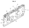
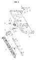
- the sensing unit 70 may be disposed at a lower side of the transfer belt 51, and includes a plurality of sensors 71 that may be disposed opposite to a lower surface of the transfer belt 51 to check the toner on the transfer belt 51, a sensor housing 72 to accommodate the plurality of sensors 71 while allowing the plurality of sensors 71 to be installed therein, and a shutter 73 installed at the sensor housing 72 so as to be moveable, for example, in a width direction of the transfer belt 51 to open and close upper portions of the sensors 71.
- the sensors 71 in accordance with an exemplary embodiment of the present disclosure include three sensors 71 disposed while being spaced apart from one another, for example, in a width direction of the transfer belt 51.
- the shutter 73 includes three penetration parts 73b corresponding to the three sensors 71, respectively.
- the shutter 73 includes a protrusion part 73a protruding from the sensor housing 72 outwards to receive force from a lever 84.
- the sensor 71 includes an optical sensor, and although not shown, the sensor 71 may be provided at an inside thereof with a light emitting part and a light receiving part.
- a lighting window 71a allowing light to pass therethrough may be provided at a surface facing the transfer belt 51 (an upper surface of the sensor 71 according to an embodiment of the present disclosure).
- the lighting window 71a of the senor 71 may be kept closed while being covered by the shutter, and in a case when a toner on the transfer belt 51 needs to be checked, the lighting window 71a may be open by moving the shutter 73.
- a shutter driving device 80 may be installed at the body frame 15 to move the shutter 73.
- the shutter driving device 80 includes a driving motor 81 to generate a rotating force, a worm 82 rotated by the driving motor 81, a worm wheel 83 rotated by rotation of the worm 82 while teethed with the worm 82, and a lever 84 rotatably installed at the body frame 15 and rotated by a rotation of the worm wheel 83 to move the shutter 73 in a first direction.
- a lever spring 86 may elastically support the lever 84 such that a support part 84a of the lever 84 is kept in a state of being supported by a cam part 83a of the worm wheel 83.
- a rotation position detecting sensor 85 may sense a rotating position of the worm wheel 83.
- a driving case 87 may be included to accommodate components of the shutter driving device 80 .
- the worm wheel 83 may be provided at one side surface thereof with the cam part 83a so as to press the lever 84 according to a rotation of the worm wheel 83 such that the lever 84 is rotated, and at the other side surface thereof with a sensed part 83b that allows the rotation angle of the worm wheel 83 to be sensed by the rotation position detecting sensor 85.
- the sensed part 83b may be provided in an arc shape extending in a circumferential direction of the worm wheel 83.
- the lever 84 includes the support part 84a extending downward and supported by an outer circumferential surface of the cam part 83a, and a protrusion part 84b extending upward and locked with the protrusion part 73a of the shutter 73.
- the lever 84 presses the protrusion part 73a while rotating according to the rotation of the worm wheel 83, such that the shutter 73 is moved in the first direction.
- the sensing unit 70 includes a shutter spring 74 to elastically support the shutter 73 such that the shutter 73 is moved in a second direction opposite to the first direction.
- the shutter spring 74 in accordance with an embodiment of the present disclosure may be formed using a coil spring having one end connected to the sensor housing 72 and the other end connected to the shutter 73.
- the rotation position detecting sensor 85 may be formed using an optical sensor including a light emitting part 85a and a light receiving part 85b.
- the sensed part 83b blocks light, which is transmitted from the light emitting part 85a to the light receiving part 85b, while passing through an area between the light emitting part 85a and the light receiving part 85b depending on the rotation angle of the worm wheel 83. Accordingly, a position of the cam part 83a and the position of the lever 84 may be recognized.
- a first setting angle of the worm wheel 83 corresponding to a state in which the lighting window 71 a of the sensor 71, is closed by the shutter 73
- a second setting angle of the worm wheel 83 representing a position at which the penetration part 73b of the shutter 73, corresponds to the sensor 71.
- the lighting window 71a of the sensor 71 may be kept in a state of being closed by the shutter 73.
- the worm 82 and the worm wheel 83 may be rotated by operating the driving motor 81.
- the cam part 83a provided at the worm wheel 83 moves the support part 84a of the lever 84, for example, toward an outside in a radial direction of the worm wheel 83.
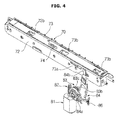
- the lever 84 may be rotated, for example, counterclockwise as illustrated in FIG. 4 , for example.
- the pressing part 84b applies force to the shutter 73 through the protrusion part 73a such that the shutter 73 is moved in a first direction 100.
- the penetration parts 73b provided at the shutter 73 move to positions corresponding to the sensors 71, respectively, thereby causing the lighting windows 71 of the sensors 71 to be open.
- Rotation of the worm wheel 83 at the second setting angle may be sensed depending on whether the sensed part 83b is located between the light emitting part 85a and the light receiving part 85b of the rotation position detecting sensor 85. If the rotation position detecting sensor 85 senses that the worm wheel 83 is rotated, for example, at a first setting angle, the operation of the driving motor 81 stops.
- the rotations of the worm 82 and the worm wheel 83 stop as the operation of the driving motor 81 stops, in which the cam part 83a continues to push the support part 84a of the lever 84 toward an outside in the radial direction of the worm wheel 83 and thus the shutter 73 remains moved in the first direction. Accordingly, the lighting window 71a of the sensor 71 is kept open.
- the driving motor 81 operates to rotate the worm 82 and the worm wheel 83.
- the support part 84a which was moved toward the outside in the radial direction of the worm wheel 83 by the cam part 83a according to the rotation of the worm wheel 83, may be moved toward an inside in the radial direction of the worm wheel 83, for example, through the elastic restoring force of the lever spring 86, and thus the lever 84 may be rotated, for example, clockwise.
- the pressing part 84b of the lever 84 becomes distant from the protrusion part 73a in a direction opposite to the protrusion part 73a.
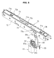
- the shutter 73 which may be elastically supported by the shutter spring 74 , is moved in a second direction 200 by the elastic restoring force of the shutter spring 74, as illustrated in FIG. 5 , for example.
- the penetration part 73b provided at the shutter 73 may be moved, for example, to a position at which the penetration part 73b does not correspond to the sensor 71, thereby causing the lighting window 71a of the sensor 71 to be closed by the shutter 73, for example, as illustrated in FIG. 5 .
- the lighting window 71a of the sensor 71 is open only when the toner on the transfer belt 51 is checked, the contamination of the sensor 71 is reduced and thus a cleaning period of the sensor 71 may be extended.
- the shutter driving device 80 in accordance with an exemplary embodiment of the present disclosure is illustrated as transmitting power to the lever 84 through the worm 82 and the worm wheel 83, the present disclosure is not limited thereto. Transmitting power through a different scheme may used.
Landscapes
- Physics & Mathematics (AREA)
- General Physics & Mathematics (AREA)
- Engineering & Computer Science (AREA)
- Microelectronics & Electronic Packaging (AREA)
- Electrostatic Charge, Transfer And Separation In Electrography (AREA)
- Control Or Security For Electrophotography (AREA)
- Electrophotography Configuration And Component (AREA)
Applications Claiming Priority (1)
| Application Number | Priority Date | Filing Date | Title |
|---|---|---|---|
| KR1020130032129A KR20140117132A (ko) | 2013-03-26 | 2013-03-26 | 화상형성장치 |
Publications (2)
| Publication Number | Publication Date |
|---|---|
| EP2787392A2 true EP2787392A2 (de) | 2014-10-08 |
| EP2787392A3 EP2787392A3 (de) | 2015-02-18 |
Family
ID=50241248
Family Applications (1)
| Application Number | Title | Priority Date | Filing Date |
|---|---|---|---|
| EP14159244.4A Withdrawn EP2787392A3 (de) | 2013-03-26 | 2014-03-12 | Bilderzeugungsvorrichtung |
Country Status (4)
| Country | Link |
|---|---|
| US (1) | US20140294420A1 (de) |
| EP (1) | EP2787392A3 (de) |
| KR (1) | KR20140117132A (de) |
| CN (1) | CN104076660A (de) |
Cited By (2)
| Publication number | Priority date | Publication date | Assignee | Title |
|---|---|---|---|---|
| EP3200025B1 (de) * | 2014-09-26 | 2020-08-12 | Hewlett-Packard Development Company, L.P. | Bilderzeugungsvorrichtung |
| WO2024043943A1 (en) * | 2022-08-25 | 2024-02-29 | Hewlett-Packard Development Company, L.P. | Structure for opening and closing sensor unit for image quality calibration |
Families Citing this family (10)
| Publication number | Priority date | Publication date | Assignee | Title |
|---|---|---|---|---|
| JP6320125B2 (ja) | 2014-03-31 | 2018-05-09 | キヤノン株式会社 | 画像形成装置 |
| JP2015197558A (ja) * | 2014-03-31 | 2015-11-09 | キヤノン株式会社 | 画像形成装置 |
| JP6459671B2 (ja) * | 2015-03-17 | 2019-01-30 | 富士ゼロックス株式会社 | 画像形成装置 |
| JP6532275B2 (ja) | 2015-04-22 | 2019-06-19 | キヤノン株式会社 | センサユニット及び画像形成装置 |
| JP6991716B2 (ja) * | 2017-01-20 | 2022-01-12 | キヤノン株式会社 | センサユニットおよび画像形成装置 |
| JP6814677B2 (ja) * | 2017-03-28 | 2021-01-20 | 株式会社沖データ | 画像形成装置 |
| KR20180129125A (ko) * | 2017-05-25 | 2018-12-05 | 에이치피프린팅코리아 유한회사 | 화상형성장치 및 그 제어방법 |
| KR20240001558A (ko) | 2022-06-27 | 2024-01-03 | 휴렛-팩커드 디벨롭먼트 컴퍼니, 엘.피. | 토너 카트리지의 토너 잔량을 감지하는 센서의 개폐 구조 |
| JP2024070750A (ja) * | 2022-11-11 | 2024-05-23 | キヤノン株式会社 | 画像形成装置 |
| WO2026080074A1 (en) * | 2024-10-10 | 2026-04-16 | Hewlett-Packard Development Company, L.P. | Motor to control an image transfer belt and calibration sensor |
Family Cites Families (5)
| Publication number | Priority date | Publication date | Assignee | Title |
|---|---|---|---|---|
| JP4377491B2 (ja) * | 1999-09-28 | 2009-12-02 | 東芝テック株式会社 | 画像形成装置 |
| JP2006215203A (ja) * | 2005-02-02 | 2006-08-17 | Kyocera Mita Corp | 画像形成装置 |
| JP2009063748A (ja) * | 2007-09-05 | 2009-03-26 | Kyocera Mita Corp | 検出器の清掃装置及び画像形成装置 |
| JP4560571B2 (ja) * | 2008-07-15 | 2010-10-13 | シャープ株式会社 | 転写ベルト清掃機能付き画像形成装置 |
| JP5289421B2 (ja) * | 2010-11-30 | 2013-09-11 | 京セラドキュメントソリューションズ株式会社 | 画像形成装置 |
-
2013
- 2013-03-26 KR KR1020130032129A patent/KR20140117132A/ko not_active Withdrawn
-
2014
- 2014-03-12 EP EP14159244.4A patent/EP2787392A3/de not_active Withdrawn
- 2014-03-21 CN CN201410108078.5A patent/CN104076660A/zh active Pending
- 2014-03-26 US US14/225,955 patent/US20140294420A1/en not_active Abandoned
Non-Patent Citations (1)
| Title |
|---|
| None |
Cited By (2)
| Publication number | Priority date | Publication date | Assignee | Title |
|---|---|---|---|---|
| EP3200025B1 (de) * | 2014-09-26 | 2020-08-12 | Hewlett-Packard Development Company, L.P. | Bilderzeugungsvorrichtung |
| WO2024043943A1 (en) * | 2022-08-25 | 2024-02-29 | Hewlett-Packard Development Company, L.P. | Structure for opening and closing sensor unit for image quality calibration |
Also Published As
| Publication number | Publication date |
|---|---|
| EP2787392A3 (de) | 2015-02-18 |
| CN104076660A (zh) | 2014-10-01 |
| US20140294420A1 (en) | 2014-10-02 |
| KR20140117132A (ko) | 2014-10-07 |
Similar Documents
| Publication | Publication Date | Title |
|---|---|---|
| EP2787392A2 (de) | Bilderzeugungsvorrichtung | |
| US9182736B2 (en) | Image forming apparatus | |
| US8873117B2 (en) | Sheet transport device and image forming apparatus | |
| US20140348531A1 (en) | Image forming apparatus | |
| KR20160036919A (ko) | 화상형성장치 | |
| KR101818207B1 (ko) | 화상형성장치 | |
| US20100080581A1 (en) | Image-Forming Device | |
| JP7535239B2 (ja) | シート搬送装置、画像読取装置及び画像形成装置 | |
| JP2020085940A (ja) | 定着装置、及び、画像形成装置 | |
| KR100565094B1 (ko) | 용지검출장치 및 이를 구비한 화상형성장치 | |
| US8131175B2 (en) | Image forming apparatus having structure to clean optical sensor and method of using the same | |
| US9436146B2 (en) | Regulation device, image forming apparatus using the same, and a method thereof | |
| US9134683B2 (en) | Image forming apparatus having a cleaning unit to clean an optical sensor unit | |
| JP2012168298A (ja) | 厚さ検出装置、画像形成装置、画像形成方法、画像形成プログラム及び記録媒体 | |
| JP2012192993A (ja) | 記録媒体収納装置および画像形成装置 | |
| EP3101480A1 (de) | Bilderzeugungsvorrichtung und steuerungsverfahren dafür | |
| JP6868955B2 (ja) | 用紙搬送装置およびそれを備える画像形成装置 | |
| JP2006072224A (ja) | 画像形成装置 | |
| WO2022076045A1 (en) | Transfer of printing medium in simplex path and duplex path | |
| JP2005309320A (ja) | 画像形成装置 | |
| JP2016206584A (ja) | 画像形成装置 |
Legal Events
| Date | Code | Title | Description |
|---|---|---|---|
| PUAI | Public reference made under article 153(3) epc to a published international application that has entered the european phase |
Free format text: ORIGINAL CODE: 0009012 |
|
| 17P | Request for examination filed |
Effective date: 20140312 |
|
| AK | Designated contracting states |
Kind code of ref document: A2 Designated state(s): AL AT BE BG CH CY CZ DE DK EE ES FI FR GB GR HR HU IE IS IT LI LT LU LV MC MK MT NL NO PL PT RO RS SE SI SK SM TR |
|
| AX | Request for extension of the european patent |
Extension state: BA ME |
|
| PUAL | Search report despatched |
Free format text: ORIGINAL CODE: 0009013 |
|
| AK | Designated contracting states |
Kind code of ref document: A3 Designated state(s): AL AT BE BG CH CY CZ DE DK EE ES FI FR GB GR HR HU IE IS IT LI LT LU LV MC MK MT NL NO PL PT RO RS SE SI SK SM TR |
|
| AX | Request for extension of the european patent |
Extension state: BA ME |
|
| RIC1 | Information provided on ipc code assigned before grant |
Ipc: G03G 15/00 20060101AFI20150112BHEP |
|
| STAA | Information on the status of an ep patent application or granted ep patent |
Free format text: STATUS: THE APPLICATION IS DEEMED TO BE WITHDRAWN |
|
| 18D | Application deemed to be withdrawn |
Effective date: 20150819 |