EP2787404A1 - Procédé de fonctionnement d'un système périphérique décentralisé - Google Patents
Procédé de fonctionnement d'un système périphérique décentralisé Download PDFInfo
- Publication number
- EP2787404A1 EP2787404A1 EP13162373.8A EP13162373A EP2787404A1 EP 2787404 A1 EP2787404 A1 EP 2787404A1 EP 13162373 A EP13162373 A EP 13162373A EP 2787404 A1 EP2787404 A1 EP 2787404A1
- Authority
- EP
- European Patent Office
- Prior art keywords
- master
- slave
- synchronization
- during
- time interval
- Prior art date
- Legal status (The legal status is an assumption and is not a legal conclusion. Google has not performed a legal analysis and makes no representation as to the accuracy of the status listed.)
- Withdrawn
Links
Images


Classifications
-
- G—PHYSICS
- G05—CONTROLLING; REGULATING
- G05B—CONTROL OR REGULATING SYSTEMS IN GENERAL; FUNCTIONAL ELEMENTS OF SUCH SYSTEMS; MONITORING OR TESTING ARRANGEMENTS FOR SUCH SYSTEMS OR ELEMENTS
- G05B19/00—Program-control systems
- G05B19/02—Program-control systems electric
- G05B19/04—Program control other than numerical control, i.e. in sequence controllers or logic controllers
- G05B19/042—Program control other than numerical control, i.e. in sequence controllers or logic controllers using digital processors
- G05B19/0421—Multiprocessor system
-
- H—ELECTRICITY
- H04—ELECTRIC COMMUNICATION TECHNIQUE
- H04L—TRANSMISSION OF DIGITAL INFORMATION, e.g. TELEGRAPHIC COMMUNICATION
- H04L12/00—Data switching networks
- H04L12/28—Data switching networks characterised by path configuration, e.g. LAN [Local Area Networks] or WAN [Wide Area Networks]
- H04L12/40—Bus networks
- H04L12/40169—Flexible bus arrangements
- H04L12/40176—Flexible bus arrangements involving redundancy
- H04L12/40195—Flexible bus arrangements involving redundancy by using a plurality of nodes
-
- H—ELECTRICITY
- H04—ELECTRIC COMMUNICATION TECHNIQUE
- H04L—TRANSMISSION OF DIGITAL INFORMATION, e.g. TELEGRAPHIC COMMUNICATION
- H04L12/00—Data switching networks
- H04L12/28—Data switching networks characterised by path configuration, e.g. LAN [Local Area Networks] or WAN [Wide Area Networks]
- H04L12/40—Bus networks
- H04L12/403—Bus networks with centralised control, e.g. polling
- H04L12/4035—Bus networks with centralised control, e.g. polling in which slots of a TDMA packet structure are assigned based on a contention resolution carried out at a master unit
-
- G—PHYSICS
- G05—CONTROLLING; REGULATING
- G05B—CONTROL OR REGULATING SYSTEMS IN GENERAL; FUNCTIONAL ELEMENTS OF SUCH SYSTEMS; MONITORING OR TESTING ARRANGEMENTS FOR SUCH SYSTEMS OR ELEMENTS
- G05B2219/00—Program-control systems
- G05B2219/20—Pc systems
- G05B2219/24—Pc safety
- G05B2219/24186—Redundant processors are synchronised
-
- G—PHYSICS
- G05—CONTROLLING; REGULATING
- G05B—CONTROL OR REGULATING SYSTEMS IN GENERAL; FUNCTIONAL ELEMENTS OF SUCH SYSTEMS; MONITORING OR TESTING ARRANGEMENTS FOR SUCH SYSTEMS OR ELEMENTS
- G05B2219/00—Program-control systems
- G05B2219/20—Pc systems
- G05B2219/25—Pc structure of the system
- G05B2219/25483—Synchronize several controllers using messages over data bus
-
- H—ELECTRICITY
- H04—ELECTRIC COMMUNICATION TECHNIQUE
- H04L—TRANSMISSION OF DIGITAL INFORMATION, e.g. TELEGRAPHIC COMMUNICATION
- H04L12/00—Data switching networks
- H04L12/28—Data switching networks characterised by path configuration, e.g. LAN [Local Area Networks] or WAN [Wide Area Networks]
- H04L12/40—Bus networks
- H04L2012/4026—Bus for use in automation systems
Definitions
- the invention relates to a method for operating a decentralized peripheral system with at least two peripheral modules, which are arranged in a peripheral device having several peripheral modules or in each case in one of two such peripheral devices, wherein an automation device can be connected to the peripheral device or devices via a bus and a field device in Form of a sensor or actuator is redundantly connected to the two peripheral modules, each of which transmit data to the field device or receive data from it during a peripheral module cycle.
- an automation system which is suitable for carrying out the method.
- H systems In the automation environment, increasingly highly available solutions (H systems) are required, which are suitable for reducing any downtimes of the system to a minimum.
- H systems usually have two multiple modules having automation equipment, which can be read and / or write access to the peripherals connected to the automation devices provided with multiple peripheral modules both automation devices.
- One of the two programmable controllers leads the world with regard to the peripherals connected to the system. This means that outputs to the peripheral units or output information for these peripheral units are performed only by one of the two automation devices, which works as a master or has taken over the master function. So that both automation devices can run synchronously, they are synchronized at regular intervals.
- peripheral modules of one peripheral unit or two peripheral modules of two such peripherals to operate redundantly, with a sensor or actuator is redundantly connected to the respective (partner) peripheral assembly and the peripheral units are connected via a bus with a plurality of modules having automation device in the form of a central or expansion device.
- a system is z.
- Siemens catalog ST 70, Chapter 8, 2012 edition known.
- a failure of one of these peripheral modules can only be detected by means of a suitable higher-level "library software", whereby suitable reactions take place, for example, within the scope of a setpoint correction only with a time delay.
- the I / O modules do not have any information about their redundant interconnection.
- the invention has for its object to provide a method of the type mentioned, by means of which a simple failure detection of Peripheriebauopathy is made possible.
- a decentralized peripheral system is provided, which is suitable for carrying out the method.
- the master and the slave monitor each other.
- the master and the slave exchange information, and further, during such a cycle, the master and the slave access the field device.
- the field device is designed as a sensor
- the sensor transmits process input data (read access) to the master and the slave
- the master and the slave supply the process output data to the actuator (write access) ,
- the slave cycle is brought in time to the master cycle, which means a "synchronization" of the two peripheral modules.
- the synchronized operation is maintained after the synchronization.
- the master starts an unsynchronized master cycle, if the master has not received the scheduled slave synchronization acknowledgments during predetermined master time intervals.
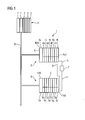
- FIG. 1 1 denotes an automation system which is provided for controlling a technical process or a system.
- Components of this automation system 1 are in the present embodiment, a plurality of modules 2 exhibiting automation device 3, a two peripheral devices 4, 5 exhibiting decentralized peripheral system 6 and a sensor 7.
- the peripheral devices 4, 5 are each provided with a plurality of peripheral modules 4a, 4b,..., 5a, 5b,..., Wherein one of these peripheral modules 4a, 5a of the respective peripheral devices 4, 5 is designed as an interface module IM4, IM5.
- These interface modules IM4, IM5 are provided for connection to a decentralized fieldbus 8 designed for high communication speeds, for example to a fieldbus "PROFIBUS DP" known per se.
- these interface modules IM4, IM5 access the peripheral modules 4a, 4b,..., 5a, 5b,... To read and / or write.
- the process input data (actual values) of the sensors provided by the peripheral modules designed as input modules are read in and transmitted to the programmable controller 3 by the controller boards IM4, IM5.
- the controller modules IM4, IM5 are supplied by the programmable controller 3 as part of a write access Process output data (setpoints) forwarded to the output modules designed as peripheral modules for controlling actuators.
- the modules 2 of the programmable controller 3, z. B. modules in the form of CPU, controller and / or input / output and / or other functional modules, as well as the peripheral modules of the peripheral devices 4, 5 are each connected via a backplane bus, not shown here.
- the automation system 1 may be provided with further automation devices and / or distributed peripheral devices, depending on a control task to be solved.
- the automation system 1 can be connected via a bus (not illustrated here) to engineering systems, operator control and monitoring systems, asset management systems and / or servers suitable for a process control system.
- the two peripheral modules are first coupled via a synchronization line 9 and a sensor 7 redundantly connected to these two peripheral modules.
- the peripheral modules 4i, 5i designed as process input modules Pe4, Pe5 are connected to one another via the synchronization line 9 and the sensor 7 is connected redundantly to these two process input modules Pe4, Pe5 via lines 10, 11.
- the process input module Pe4 is parameterized as master M and the process input module Pe5 as slave S, wherein this parameterization takes place during a parameterization phase by means of the programmable controller 3 or an engineering system not shown here.
- a communication cycle of the field bus 8 designed for high communication speeds is shorter than the peripheral device cycles, so that all units connected to this bus can exchange information in real time. Accordingly, master and slave cycles during which the master M and slave S receive sensor data are longer than the peripheral cycles, because during these peripheral cycles, each of the peripheral boards exchanges information with the interface boards IM4, IM5.
- the master M After the parameterization of the peripheral module Pe4 as master M and the peripheral module Pe5 as slave S, the master M transmits to the slave S a first master synchronization request A1 and immediately after this transmission starts a read cycle unsynchronized or not synchronized with the slave S for reading data of the sensor 7, which is in FIG. 2 is referred to as "cycle Mns" and below is called an unsynchronized master cycle.
- the master M executes further such unsynchronized master cycles Mns if the master M does not receive the first slave synchronization acknowledgment Q1 during a respective first master time interval Zm1.
- the slave S In the event that the slave S receives this first master synchronization request A1 during a first slave time interval Zs1 - indicating to the slave S that the master M is in operation - the slave S responds to the master M by means of a first one Slave synchronization acknowledgment Q1, whereby the master M, the operation of the slave S is displayed.
- the master M has received the first slave synchronization acknowledgment Q1 during the first master time interval Zm1.
- the master M transmits to the slave S a second master synchronization request A2 and waits for a second master time interval Zm2 for a second synchronization acknowledgment Q2 of the slave S.
- This second synchronization acknowledgment Q2 is transmitted by the slave S to the master M in the event that the slave S has received the second master synchronization request A2 during a second slave time interval Zs2, the slave S starting a read cycle after the transmission of this second synchronization acknowledgment Q2.
- This read cycle is then synchronized with a read cycle of the master M if the master M during a second master time interval Zm2, the second slave synchronization acknowledgment Q2 has received.
- These read cycles - hereinafter referred to as master M as Msyn ( FIG. 2 ) and with respect to the slave S as ssyn ( FIG. 3 ), synchronized if on the one hand the master M receives a third synchronization acknowledgment Q3 during a respective third time interval Zm3 and on the other hand the slave S receives a third master synchronization request A3 during a third slave time interval Zs3.
- the slave S first transmits to the master M immediately after a read cycle Ssyn the third synchronization acknowledgment Q3 and the master M to the slave S immediately after receiving this third synchronization acknowledgment Q3, the third master synchronization request A3.
- the third master and slave time intervals Zm3, Zs3, which correspond to the first master time interval Zm1, are selected such that the partner peripheral modules, ie the master M and the slave S, recognize as quickly as possible whether the respective partner peripheral module is still working available or still ready for use.
- the respective time intervals Zm1, Zm3 and Zs3 correspond to the sum of twice the transmission time of the respective synchronization information (master synchronization request, slave synchronization acknowledgment), twice the maximum response time to the reception of synchronization information and a margin allowance time.
- the second master and slave time intervals Zm2, Zs2 are selected such that master M and slave S can synchronize themselves.
- the respective time intervals Zm2, Zs2 correspond to the sum of twice the transmission time of the respective synchronization information (master synchronization request, slave synchronization acknowledgment), twice the maximum response time to the reception of synchronization information, the maximum master or slave cycle time and a tolerance allowance time.
- the first slave time interval Zs1 is greater than one slave cycle selected, this time interval being a slave wait time corresponds, during which the slave S can recognize on the basis of the master synchronization request A1, whether the master M is ready or present at all or whether an I / O module is ever configured as a master.
- the master M does not receive the corresponding slave synchronization acknowledgments Q1, Q2, Q3 during the master time intervals Zm1, Zm2, Zm3, the master M transmits to the slave S the first synchronization request A1 and starts the unsynchronized read cycle, respectively mns. In these cases, the slave S has failed.
- the slave S In cases where the slave S does not receive the corresponding master synchronization requests A1, A2, A3 during the slave time intervals Zs1, Zs2, Zs3, indicating a failure of the master M, the slave S starts an unsynchronized read cycle Sns , After such an unsynchronized read cycle Sns, the slave S monitors the reception of the first master synchronization request A1 first and then - if the slave S has received it - the reception of the second master synchronization request A2. In the event that the slave S has received the respective request A1, A2, the slave S respectively supplies the first and the second slave synchronization acknowledgment Q1, Q2 to the master M and finally starts the synchronized read cycle Ssyn as described.
Landscapes
- Engineering & Computer Science (AREA)
- Computer Networks & Wireless Communication (AREA)
- Signal Processing (AREA)
- Physics & Mathematics (AREA)
- General Physics & Mathematics (AREA)
- Automation & Control Theory (AREA)
- Hardware Redundancy (AREA)
Priority Applications (1)
| Application Number | Priority Date | Filing Date | Title |
|---|---|---|---|
| EP13162373.8A EP2787404A1 (fr) | 2013-04-04 | 2013-04-04 | Procédé de fonctionnement d'un système périphérique décentralisé |
Applications Claiming Priority (1)
| Application Number | Priority Date | Filing Date | Title |
|---|---|---|---|
| EP13162373.8A EP2787404A1 (fr) | 2013-04-04 | 2013-04-04 | Procédé de fonctionnement d'un système périphérique décentralisé |
Publications (1)
| Publication Number | Publication Date |
|---|---|
| EP2787404A1 true EP2787404A1 (fr) | 2014-10-08 |
Family
ID=48095581
Family Applications (1)
| Application Number | Title | Priority Date | Filing Date |
|---|---|---|---|
| EP13162373.8A Withdrawn EP2787404A1 (fr) | 2013-04-04 | 2013-04-04 | Procédé de fonctionnement d'un système périphérique décentralisé |
Country Status (1)
| Country | Link |
|---|---|
| EP (1) | EP2787404A1 (fr) |
Cited By (1)
| Publication number | Priority date | Publication date | Assignee | Title |
|---|---|---|---|---|
| CN110058546A (zh) * | 2019-04-08 | 2019-07-26 | 珠海智途科技有限公司 | 一种驱动系统 |
Citations (4)
| Publication number | Priority date | Publication date | Assignee | Title |
|---|---|---|---|---|
| EP0478290A2 (fr) * | 1990-09-26 | 1992-04-01 | Honeywell Inc. | Procédé de maintien de la synchronisation d'un processeur secondaire librement oscillant |
| EP1283468A2 (fr) * | 2001-07-11 | 2003-02-12 | Siemens Aktiengesellschaft | Unité centrale pour un système d'automatisation redondant |
| EP1857938A1 (fr) * | 2005-01-31 | 2007-11-21 | Yokogawa Electric Corporation | Appareil de traitement de l'information et procede correspondant |
| EP2031470A2 (fr) * | 2007-08-31 | 2009-03-04 | Siemens Energy & Automation, Inc. | Systèmes et/ou dispositifs pour contrôler la synchronisation des cycles de diagnostic et de conversion de données pour des applications E/S redondantes |
-
2013
- 2013-04-04 EP EP13162373.8A patent/EP2787404A1/fr not_active Withdrawn
Patent Citations (4)
| Publication number | Priority date | Publication date | Assignee | Title |
|---|---|---|---|---|
| EP0478290A2 (fr) * | 1990-09-26 | 1992-04-01 | Honeywell Inc. | Procédé de maintien de la synchronisation d'un processeur secondaire librement oscillant |
| EP1283468A2 (fr) * | 2001-07-11 | 2003-02-12 | Siemens Aktiengesellschaft | Unité centrale pour un système d'automatisation redondant |
| EP1857938A1 (fr) * | 2005-01-31 | 2007-11-21 | Yokogawa Electric Corporation | Appareil de traitement de l'information et procede correspondant |
| EP2031470A2 (fr) * | 2007-08-31 | 2009-03-04 | Siemens Energy & Automation, Inc. | Systèmes et/ou dispositifs pour contrôler la synchronisation des cycles de diagnostic et de conversion de données pour des applications E/S redondantes |
Cited By (1)
| Publication number | Priority date | Publication date | Assignee | Title |
|---|---|---|---|---|
| CN110058546A (zh) * | 2019-04-08 | 2019-07-26 | 珠海智途科技有限公司 | 一种驱动系统 |
Similar Documents
| Publication | Publication Date | Title |
|---|---|---|
| EP2504739B1 (fr) | Système de commande pour commander des processus critiques sur le plan de la sécurité et des processus non critiques sur le plan de la sécurité | |
| EP2504740B1 (fr) | Module de sécurité pour un appareil d'automatisation | |
| EP2657797B1 (fr) | Procédé de fonctionnement d'un système d'automatisation redondant | |
| DE102007001576B4 (de) | Verfahren zur Synchronisierung redundanter Steuerungen für stoßfreies Failover unter normalen Bedingungen und bei Fehlanpasssung | |
| EP2857913B1 (fr) | Système d'automatisation redondant | |
| EP3622357B1 (fr) | Système de commande servant à commander des processus critiques pour la sécurité et non-critiques pour la sécurité, muni d'une fonctionnalité maître-esclave | |
| DE102016000126B4 (de) | Serielles Bussystem mit Koppelmodulen | |
| DE19744071B4 (de) | Eine programmierbare Logiksteuervorrichtung verwendendes Steuerungssystem | |
| EP2817682A1 (fr) | Procédé permettant un fonctionnement à sécurité intégrée d'un système de commande de processus à l'aide de dispositifs de commande redondants | |
| EP0782722B1 (fr) | Procede et dispositif permettant de commander et d'activer des detecteurs et/ou des organes d'actionnement relies par un systeme de bus | |
| EP1860564A1 (fr) | Procédé et dispositif destinés à l'échange de données sur la base du protocole de communication OPC entre des composants redondants d'un système d'automatisation | |
| EP4179425B1 (fr) | Procédé de transfert d'une application logicielle d'un premier à un second dispositif de traitement des données | |
| EP2806316B1 (fr) | Procédé destiné au fonctionnement d'un système d'automatisation | |
| EP3143506B1 (fr) | Procédé et système permettant d'attribuer une autorisation de commande à un ordinateur | |
| EP2418580B1 (fr) | Procédé destiné au fonctionnement d'un réseau et réseau | |
| EP2860598B1 (fr) | Procédé d'operation d' un système d'automatisation redondant, dans lequel l' esclave exécute de fonctions diagnostiques | |
| EP3401742B1 (fr) | Système d'automatisation et procédé de fonctionnement | |
| EP2787404A1 (fr) | Procédé de fonctionnement d'un système périphérique décentralisé | |
| EP2942686B1 (fr) | Système de commande et de transmission de données pour la transmission de données liées à la sécurité par l'intermédiaire d'un support de communication | |
| DE102011082598A1 (de) | Steueranordnung | |
| EP3267271B1 (fr) | Système d'automatisation et procédé de fonctionnement | |
| EP2048555A1 (fr) | Dispositif de sortie analogique avec detection d'erreurs | |
| WO2005057306A1 (fr) | Unite peripherique d'un systeme de commande redondant | |
| DE10121322B4 (de) | Datenübertragungssystem mit verteiler Leitfunktionalität | |
| EP1426862B1 (fr) | Synchronisation de traitement de données dans des unités de traitement redondantes d'un système de traitement de données |
Legal Events
| Date | Code | Title | Description |
|---|---|---|---|
| PUAI | Public reference made under article 153(3) epc to a published international application that has entered the european phase |
Free format text: ORIGINAL CODE: 0009012 |
|
| 17P | Request for examination filed |
Effective date: 20130404 |
|
| AK | Designated contracting states |
Kind code of ref document: A1 Designated state(s): AL AT BE BG CH CY CZ DE DK EE ES FI FR GB GR HR HU IE IS IT LI LT LU LV MC MK MT NL NO PL PT RO RS SE SI SK SM TR |
|
| AX | Request for extension of the european patent |
Extension state: BA ME |
|
| STAA | Information on the status of an ep patent application or granted ep patent |
Free format text: STATUS: THE APPLICATION IS DEEMED TO BE WITHDRAWN |
|
| 18D | Application deemed to be withdrawn |
Effective date: 20150409 |