EP2787581A1 - Connecteur implantable - Google Patents
Connecteur implantable Download PDFInfo
- Publication number
- EP2787581A1 EP2787581A1 EP13162255.7A EP13162255A EP2787581A1 EP 2787581 A1 EP2787581 A1 EP 2787581A1 EP 13162255 A EP13162255 A EP 13162255A EP 2787581 A1 EP2787581 A1 EP 2787581A1
- Authority
- EP
- European Patent Office
- Prior art keywords
- cable
- cable connector
- connector
- connection device
- elements
- Prior art date
- Legal status (The legal status is an assumption and is not a legal conclusion. Google has not performed a legal analysis and makes no representation as to the accuracy of the status listed.)
- Withdrawn
Links
- 239000000560 biocompatible material Substances 0.000 claims abstract description 3
- 210000003516 pericardium Anatomy 0.000 claims description 21
- 239000008280 blood Substances 0.000 claims description 20
- 210000004369 blood Anatomy 0.000 claims description 20
- 229910052751 metal Inorganic materials 0.000 claims description 15
- 239000002184 metal Substances 0.000 claims description 15
- 230000000747 cardiac effect Effects 0.000 claims description 6
- 239000000919 ceramic Substances 0.000 claims description 6
- 239000011521 glass Substances 0.000 claims description 6
- 238000000034 method Methods 0.000 claims description 6
- 238000004891 communication Methods 0.000 claims description 5
- 210000005245 right atrium Anatomy 0.000 description 18
- 239000007943 implant Substances 0.000 description 12
- 210000001562 sternum Anatomy 0.000 description 12
- 210000005246 left atrium Anatomy 0.000 description 9
- 210000005241 right ventricle Anatomy 0.000 description 8
- 210000005240 left ventricle Anatomy 0.000 description 6
- 230000002861 ventricular Effects 0.000 description 6
- 239000004020 conductor Substances 0.000 description 5
- 230000008878 coupling Effects 0.000 description 4
- 238000010168 coupling process Methods 0.000 description 4
- 238000005859 coupling reaction Methods 0.000 description 4
- 238000005516 engineering process Methods 0.000 description 3
- 238000002513 implantation Methods 0.000 description 3
- 229910000679 solder Inorganic materials 0.000 description 3
- 210000001519 tissue Anatomy 0.000 description 3
- RTAQQCXQSZGOHL-UHFFFAOYSA-N Titanium Chemical compound [Ti] RTAQQCXQSZGOHL-UHFFFAOYSA-N 0.000 description 2
- 230000000295 complement effect Effects 0.000 description 2
- 238000004146 energy storage Methods 0.000 description 2
- 230000002349 favourable effect Effects 0.000 description 2
- 230000007774 longterm Effects 0.000 description 2
- 238000004519 manufacturing process Methods 0.000 description 2
- 239000000463 material Substances 0.000 description 2
- 239000010936 titanium Substances 0.000 description 2
- 229910052719 titanium Inorganic materials 0.000 description 2
- RYGMFSIKBFXOCR-UHFFFAOYSA-N Copper Chemical compound [Cu] RYGMFSIKBFXOCR-UHFFFAOYSA-N 0.000 description 1
- 206010061218 Inflammation Diseases 0.000 description 1
- 239000000853 adhesive Substances 0.000 description 1
- 230000001070 adhesive effect Effects 0.000 description 1
- 230000009286 beneficial effect Effects 0.000 description 1
- 230000005540 biological transmission Effects 0.000 description 1
- 238000005219 brazing Methods 0.000 description 1
- 150000001875 compounds Chemical class 0.000 description 1
- 230000006378 damage Effects 0.000 description 1
- 230000002950 deficient Effects 0.000 description 1
- 230000001627 detrimental effect Effects 0.000 description 1
- 230000004069 differentiation Effects 0.000 description 1
- 230000004064 dysfunction Effects 0.000 description 1
- 239000000806 elastomer Substances 0.000 description 1
- 229920001971 elastomer Polymers 0.000 description 1
- 238000004870 electrical engineering Methods 0.000 description 1
- 239000012530 fluid Substances 0.000 description 1
- 208000015181 infectious disease Diseases 0.000 description 1
- 230000004054 inflammatory process Effects 0.000 description 1
- 238000003780 insertion Methods 0.000 description 1
- 230000037431 insertion Effects 0.000 description 1
- 238000005304 joining Methods 0.000 description 1
- 238000002844 melting Methods 0.000 description 1
- 230000008018 melting Effects 0.000 description 1
- 239000006060 molten glass Substances 0.000 description 1
- 210000004165 myocardium Anatomy 0.000 description 1
- 230000035515 penetration Effects 0.000 description 1
- 238000004382 potting Methods 0.000 description 1
- 238000003825 pressing Methods 0.000 description 1
- 238000007789 sealing Methods 0.000 description 1
- 238000009958 sewing Methods 0.000 description 1
- 238000003860 storage Methods 0.000 description 1
- 238000007920 subcutaneous administration Methods 0.000 description 1
- 239000000126 substance Substances 0.000 description 1
- 239000013589 supplement Substances 0.000 description 1
Images


Classifications
-
- H—ELECTRICITY
- H01—ELECTRIC ELEMENTS
- H01R—ELECTRICALLY-CONDUCTIVE CONNECTIONS; STRUCTURAL ASSOCIATIONS OF A PLURALITY OF MUTUALLY-INSULATED ELECTRICAL CONNECTING ELEMENTS; COUPLING DEVICES; CURRENT COLLECTORS
- H01R31/00—Coupling parts supported only by co-operation with counterpart
- H01R31/02—Intermediate parts for distributing energy to two or more circuits in parallel, e.g. splitter
-
- A—HUMAN NECESSITIES
- A61—MEDICAL OR VETERINARY SCIENCE; HYGIENE
- A61M—DEVICES FOR INTRODUCING MEDIA INTO, OR ONTO, THE BODY; DEVICES FOR TRANSDUCING BODY MEDIA OR FOR TAKING MEDIA FROM THE BODY; DEVICES FOR PRODUCING OR ENDING SLEEP OR STUPOR
- A61M60/00—Blood pumps; Devices for mechanical circulatory actuation; Balloon pumps for circulatory assistance
- A61M60/10—Location thereof with respect to the patient's body
- A61M60/122—Implantable pumps or pumping devices, i.e. the blood being pumped inside the patient's body
- A61M60/165—Implantable pumps or pumping devices, i.e. the blood being pumped inside the patient's body implantable in, on, or around the heart
- A61M60/178—Implantable pumps or pumping devices, i.e. the blood being pumped inside the patient's body implantable in, on, or around the heart drawing blood from a ventricle and returning the blood to the arterial system via a cannula external to the ventricle, e.g. left or right ventricular assist devices
- A61M60/183—Implantable pumps or pumping devices, i.e. the blood being pumped inside the patient's body implantable in, on, or around the heart drawing blood from a ventricle and returning the blood to the arterial system via a cannula external to the ventricle, e.g. left or right ventricular assist devices drawing blood from both ventricles, e.g. bi-ventricular assist devices [BiVAD]
-
- A—HUMAN NECESSITIES
- A61—MEDICAL OR VETERINARY SCIENCE; HYGIENE
- A61M—DEVICES FOR INTRODUCING MEDIA INTO, OR ONTO, THE BODY; DEVICES FOR TRANSDUCING BODY MEDIA OR FOR TAKING MEDIA FROM THE BODY; DEVICES FOR PRODUCING OR ENDING SLEEP OR STUPOR
- A61M60/00—Blood pumps; Devices for mechanical circulatory actuation; Balloon pumps for circulatory assistance
- A61M60/80—Constructional details other than related to driving
- A61M60/855—Constructional details other than related to driving of implantable pumps or pumping devices
- A61M60/871—Energy supply devices; Converters therefor
- A61M60/878—Electrical connections within the patient's body
-
- A—HUMAN NECESSITIES
- A61—MEDICAL OR VETERINARY SCIENCE; HYGIENE
- A61M—DEVICES FOR INTRODUCING MEDIA INTO, OR ONTO, THE BODY; DEVICES FOR TRANSDUCING BODY MEDIA OR FOR TAKING MEDIA FROM THE BODY; DEVICES FOR PRODUCING OR ENDING SLEEP OR STUPOR
- A61M60/00—Blood pumps; Devices for mechanical circulatory actuation; Balloon pumps for circulatory assistance
- A61M60/80—Constructional details other than related to driving
- A61M60/855—Constructional details other than related to driving of implantable pumps or pumping devices
- A61M60/871—Energy supply devices; Converters therefor
- A61M60/88—Percutaneous cables
-
- A—HUMAN NECESSITIES
- A61—MEDICAL OR VETERINARY SCIENCE; HYGIENE
- A61M—DEVICES FOR INTRODUCING MEDIA INTO, OR ONTO, THE BODY; DEVICES FOR TRANSDUCING BODY MEDIA OR FOR TAKING MEDIA FROM THE BODY; DEVICES FOR PRODUCING OR ENDING SLEEP OR STUPOR
- A61M2205/00—General characteristics of the apparatus
- A61M2205/04—General characteristics of the apparatus implanted
-
- A—HUMAN NECESSITIES
- A61—MEDICAL OR VETERINARY SCIENCE; HYGIENE
- A61M—DEVICES FOR INTRODUCING MEDIA INTO, OR ONTO, THE BODY; DEVICES FOR TRANSDUCING BODY MEDIA OR FOR TAKING MEDIA FROM THE BODY; DEVICES FOR PRODUCING OR ENDING SLEEP OR STUPOR
- A61M2205/00—General characteristics of the apparatus
- A61M2205/35—Communication
- A61M2205/3507—Communication with implanted devices, e.g. external control
- A61M2205/3523—Communication with implanted devices, e.g. external control using telemetric means
-
- A—HUMAN NECESSITIES
- A61—MEDICAL OR VETERINARY SCIENCE; HYGIENE
- A61M—DEVICES FOR INTRODUCING MEDIA INTO, OR ONTO, THE BODY; DEVICES FOR TRANSDUCING BODY MEDIA OR FOR TAKING MEDIA FROM THE BODY; DEVICES FOR PRODUCING OR ENDING SLEEP OR STUPOR
- A61M2205/00—General characteristics of the apparatus
- A61M2205/82—Internal energy supply devices
- A61M2205/8262—Internal energy supply devices connectable to external power source, e.g. connecting to automobile battery through the cigarette lighter
-
- A—HUMAN NECESSITIES
- A61—MEDICAL OR VETERINARY SCIENCE; HYGIENE
- A61M—DEVICES FOR INTRODUCING MEDIA INTO, OR ONTO, THE BODY; DEVICES FOR TRANSDUCING BODY MEDIA OR FOR TAKING MEDIA FROM THE BODY; DEVICES FOR PRODUCING OR ENDING SLEEP OR STUPOR
- A61M60/00—Blood pumps; Devices for mechanical circulatory actuation; Balloon pumps for circulatory assistance
- A61M60/10—Location thereof with respect to the patient's body
- A61M60/122—Implantable pumps or pumping devices, i.e. the blood being pumped inside the patient's body
- A61M60/126—Implantable pumps or pumping devices, i.e. the blood being pumped inside the patient's body implantable via, into, inside, in line, branching on, or around a blood vessel
- A61M60/148—Implantable pumps or pumping devices, i.e. the blood being pumped inside the patient's body implantable via, into, inside, in line, branching on, or around a blood vessel in line with a blood vessel using resection or like techniques, e.g. permanent endovascular heart assist devices
-
- A—HUMAN NECESSITIES
- A61—MEDICAL OR VETERINARY SCIENCE; HYGIENE
- A61M—DEVICES FOR INTRODUCING MEDIA INTO, OR ONTO, THE BODY; DEVICES FOR TRANSDUCING BODY MEDIA OR FOR TAKING MEDIA FROM THE BODY; DEVICES FOR PRODUCING OR ENDING SLEEP OR STUPOR
- A61M60/00—Blood pumps; Devices for mechanical circulatory actuation; Balloon pumps for circulatory assistance
- A61M60/20—Type thereof
- A61M60/205—Non-positive displacement blood pumps
- A61M60/216—Non-positive displacement blood pumps including a rotating member acting on the blood, e.g. impeller
-
- H—ELECTRICITY
- H01—ELECTRIC ELEMENTS
- H01R—ELECTRICALLY-CONDUCTIVE CONNECTIONS; STRUCTURAL ASSOCIATIONS OF A PLURALITY OF MUTUALLY-INSULATED ELECTRICAL CONNECTING ELEMENTS; COUPLING DEVICES; CURRENT COLLECTORS
- H01R2201/00—Connectors or connections adapted for particular applications
- H01R2201/12—Connectors or connections adapted for particular applications for medicine and surgery
Definitions
- the invention is in the field of mechanics and electrical engineering and is particularly applicable in medical technology.
- the invention particularly relates to a cable connection device which is implantable.
- Such percutaneous cables d.
- cables located in a region of their course within the patient's body and in another area of their course outside the patient's body present a risk of infection and inflammation. It is therefore desirable to have a corresponding cable in the event of complications can be easily removed and / or replaced.
- a cable connector is known, which is designed as a so-called Y-cable, ie with a connector and a permanently attached to this cable with multiple lines, which branch to two separate cables, each of the separate cables in turn a connector having.
- a cable connector is provided for the electrical connection of a percutaneous cable with two implantable pumps. The pumps are used to pump blood in the bloodstream.
- the present invention is based on the background of the prior art, the object to provide an implantable cable connector, which is particularly simple and stable and is particularly easy to handle in the implantation and the production of the connectors.
- the invention relates to an implantable cable connection device with a cable connector having two or more connector elements, with each of which an implantable cable is connectable by a plug connection, wherein the cable connector is formed as a rigid body made of a biocompatible material.
- a particularly advantageous embodiment of the invention provides that at least two, in particular three or more connector elements are arranged on the same side of the cable connector.
- a further advantageous embodiment of the invention provides that all plug connection elements are arranged on the same side of the cable connector.
- the cable connector this can be implanted so that the connector elements are each on the side of the cable connector, which can be easily reached from the outside by a minimal intervention by a minimum opening of the patient's body. The cable connector itself must then not be removed from the patient's body to replace the connectors.
- the plug connection elements can advantageously be arranged on the smallest or narrowest of the side surfaces of the cable connector.
- the invention can also be advantageously configured in that the plug-in axes of the connector elements, which are arranged together on one side of the cable connector, are aligned parallel to each other. Also, by a parallel, in particular rigid arrangement of the plug-in axes of the connector elements on the cable connector, the handling of the connectors can be simplified. Under the plug-in axes of the connector elements is in each case understood the direction in which a cable is plugged with the respective complementary connector element on the cable connector arranged on the connector element. In common hermaphrodisiac connectors, the plug-in axis is parallel to the longitudinal axis of the connector pins or the corresponding sockets.
- a parallel orientation of the stub axles of the connector elements also means that they can be performed with minimal distance from each other and that the corresponding complementary connector elements of cables can be arranged in the same way with minimum distance from each other outside of the cable connector. The overall space required and required space of the cable connection device is thus minimized.
- the invention is also realized in that the cable connector has a flat surface formed side on which the connector elements are arranged, and that all other boundary surfaces of the cable connector are convex rounded.
- a cable connector which is largely rounded off on its outer sides, can be readily implanted in a patient's body, in particular without the risk of special tissue loads in the rounded regions of the cable connector. Even with a movement of the tissue in which the cable connector is embedded, no injuries are to be feared.
- the cable connector is formed substantially hemispherical rounded.
- the cable connector may also take the form of a halved ellipsoidal or other rounded body.
- the basic form may be that of a cuboid.
- a further advantageous embodiment of the invention provides that the cable connector is designed as a housing with at least one interior.
- a cable connector produced as a compact body can on the one hand connect the various plug connection elements to one another by means of the favorable internal guidance of lines in a small space and furthermore also have an interior in which, for example, an electrical energy storage / accumulator or an electrically active element, for example an electrical circuit,
- a device for wireless communication can be arranged.
- a transponder can be arranged, which allows identification without a power supply is necessary (radio-tag).
- the interior can be filled with an adhesive, a potting compound or a fluid, but it can also remain a cavity free.
- a control device for one or more blood pump motors may be arranged.
- a microcontroller or another programmable device can be provided there.
- the cable connector consists exclusively of metal and / or glass and / or ceramic on its outer sides.
- These materials are highly biocompatible, i. H. tissue-compatible, and long-term stability, so that an existing of such a material cable connector is long-term implantable.
- the outer surfaces are advantageously designed smooth.
- the housing of the cable connector can also consist of several parts, which are joined gas-tight to the outside of the cable connector, in particular welded together, glued or potted.
- a metal element of the cable connector with a glass part be merged.
- the glass part can in turn be sealed gas-tight with a ceramic.
- a metal can also be gas-tightly connected to a ceramic or a glass by means of a metal brazing. All these joining techniques have in common that they combine a reliable fixation with simultaneous gas-tight sealing and chemical and physical strength.
- a cable connector when used in conjunction with one or more cardiac assistive blood pumps, may be placed in the space between the then-usually somewhat-reduced heart muscle and pericardium. It is also a subcutaneous arrangement of the cable connector possible, and it can be provided on this example, eyelets for sewing on the body tissue.
- the invention also relates to a cable connection device with a cable connector, a first percutaneous cable inserted therein and at least one second cable inserted into the cable connector and an implant connected to the second cable, in particular a blood pump.
- a third cable connected to the cable connector by a plug connection and a further implant connected to this third cable, in particular also an implanted blood pump, may be provided.
- the cable connection device may potentially include not only the cable connector with connector devices, but also the corresponding cables inserted therein and blood pumps or alternative implants connected thereto. Also, an inserted percutaneous cable connected to the cable connector may be part of the cable connection device.
- the cable connecting device may thus comprise a total of a system of a plurality of implants, in particular pumps, which are connected by means of cable connections via a cable connector with a percutaneous cable, which is easily accessible outside the patient's body to a cable connection.
- the cable connector in particular its housing, can also have at least one, in particular two coupling elements, for example screw threads, bayonet receptacles or the like for a fixing element, by means of which the connector is easy to manipulate, especially in a cable plugging operation.
- at least one, in particular two coupling elements for example screw threads, bayonet receptacles or the like for a fixing element, by means of which the connector is easy to manipulate, especially in a cable plugging operation.
- An advantageous embodiment of the invention also provides that on the outside of the cable connector at least two connector elements are provided side by side and that in addition a locking device is provided which, as long as one of the connectors is released, the release of the other connector blocked, in which case in particular a Locking element is provided which has two cover elements for at least partial cover each of a plug connection, wherein the locking element between two end positions is movable and in each of the end positions in each case a plug connection is blocked.
- Such a locking device prevents inadvertent release of two connectors on the cable connector at the same time, which can lead to reversed cables when reinserting. This is particularly undesirable and risky when two cable connections are made to two blood pumps located in different parts of a patient's heart or at various locations with respect to the heart in the periphery or generally in the bloodstream, the exchange of which can be detrimental.
- An advantageous method for implanting a cable connection device of the type according to the invention can also provide that the cable connector is arranged in the patient's body and then at least one, in particular two or three implantable cables are connected to the cable connector by means of plug connections.
- implantable elements such as blood pumps, which are to be connected to the cable connector can advantageously already before the implantation of the cable connector or after the implantation of the cable connector In any case, they do not have to be inserted simultaneously with the cable connector.
- the invention also relates to a method for exchanging a plurality of implantable cables connected to a cable connector according to the invention, in which first the plug connection of a first cable is released and a new first cable is connected to the cable connector by means of the plug connection and the plug connection of a second cable is released thereon a connector of the cable connector is made to a new second cable, wherein in particular the first and the second cable are each connected to a blood pump.
- connection also relates to a method for exchanging an implanted cable connected to a cable connector according to the invention, in which first a holding tool is connected to a coupling element of the cable connector, then the plug connection of the cable is released and a new cable is connected to the cable connector by means of a plug connection ,
- the cable connector can be easily held as a rigid body from the outside, while connectors are dissolved or plugged.
- the cable connector can remain implanted, and it comes only minimally in contact with alien instruments.
- a coupling element may in principle have a mechanical fit, such as a screw thread or a bayonet closure, or it may also be formed magnetically, for example, by a magnet attached to the cable connector and / or a holding tool.
- An advantageous use of the cable connection device provides that the cable connection device is connected to two heart support pumps and arranged together with these directly on a heart, in particular fixed on this or on the pericardium.
- An advantageous method for implanting a cable connecting device provides that the cable connector with two heart support pumps is electrically connected and temporally before or after the pericardium of a patient's heart is fixed.
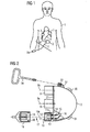
- FIG. 1 schematically shows a front view of a patient's body 1, in which a cable connector 2 of a cable connection device is implanted.
- the cable connector 2 is connected by means of a first implantable cable 3, which is designed as a percutaneous cable, with a first plug connection 3a outside the patient's body.
- percutaneous cable usually refers to a cable that penetrates the skin or other part of the boundary surface between the patient's body and the outside world.
- a percutaneous cable may also refer to an implantable cable that extends completely within the patient's body and terminates at a terminal device with which a cable extending outside of the patient's body can, for example, be inductively coupled through the skin. It can also be provided that only one plug connection 3a of the percutaneous cable is let into the skin and penetrates it.
- a second implantable cable 4 which connects the cable connector 2 to a first blood pump 5, is connected to the cable connector 2.
- a third implanted cable 6 is connected to the cable connector 2 on the one hand and a second blood pump 7 on the other hand.
- the implanted cables 3, 4, 6 are electrically connected to the cable connector 2 in each case via plug connections.
- the implanted cables are connected at their ends remote from the cable connector 2 by means of a respective further connector 3a, in each case with a further element, for example with the blood pumps 5, 7.
- the implanted cables 4, 6 can also be permanently and permanently connected to the respective blood pumps 5, 7.
- the two blood pumps 5, 7, via a single, percutaneous cable 3 can be controlled from outside the patient's body, required for the implementation of a cable portion of the skin, which is opened and permanently is traversed by a foreign body, minimized.
- a particularly advantageous embodiment results from the fact that the percutaneous cable 3 is circular in cross-section, in order to minimize the contact area between the cable and the skin of the patient's body as a whole and especially at the point of penetration through the skin.
- FIG. 2 shows schematically and partially in section a cable connector 2 in more detail, wherein the cable connector 2 has three connector elements 8, 9, 10.
- the individual connector elements On the cable connector 2 each have a hollow metal cylinder 11 which is fixed as a plug sleeve on the cable connector 2 and which has a cylinder bottom 11 a, which is fluid-tightly connected to the cable connector 2.
- the cylinder bottom 11a has recesses, through which the plug pins 12, 13 are electrically insulated and fluid-tight in that they are sealed in the cylinder bottom 11a by means of a glass filling 14 in a fluid-tight manner.
- the plug pins 12, 13 are each connected via solder joints 15 with a line, such as a copper wire 16, in turn, the contact of the connector pins 12, 13 with other connector pins of the remaining connector elements 8, 9 or electronic elements in the interior of the cable connector 2 or an energy storage in the interior of the cable connector 2 produces.
- the plug 17 has plug sleeves 18 which can be plugged onto the plug pins 12, 13 in order to produce galvanic contact therewith.
- the plug sleeves 18 are in turn connected to conductors which are guided within the plug 17 to the connected implanted cable.
- a connector housing 19 is provided which has a shape corresponding to the cylinder 11 and which is attachable to the cylinder 11.
- an O-ring 20 is provided in the plug housing 19 in an inner circumferential groove made of an elastomer which seals fluid-tight on the metal cylinder 11 outside.
- a fuse may be provided which holds the plug 17 to the cable connector 2, for example by a union nut which is screwed to the cable connector 2, or by a bayonet connection between the plug 17 and the metal cylinder eleventh
- FIG. 2 shows that the cable connector 2 has a flat front surface 21 to which the connector elements 8, 9, 10 are fixed such that their through axles 8a, 9a, 10a are parallel to each other.
- the housing part of the cable connector 2, which adjoins the flat front plate, which forms the flat front surface 21, is formed, for example, as a spherical cap or as part of a rotational ellipsoid and consists for example, made of metal, in particular titanium, or a ceramic.
- the connections between the metal and the ceramic can be made fluid-tight by melting the metal or by interim storage of a glass solder or metal solder. It is also conceivable a fluid-tight pressing of the elements by pressure application.
- Fig. 2 are also exemplary coupling elements, namely holding eyes 30, 31, shown, and a housing projection 32 in which a threaded bore 33 is located, into which a holding tool 34 can be screwed for manipulation.
- FIG. 3 shows a cable connector 2 'with only two connector elements 8, 9 on a flat front surface, wherein the connector elements 8, 9 are aligned with their respective through axles 8a, 9a parallel to each other.
- an external thread 21 is shown on the metal cylinder in the base area near the front surface of the cable connector 2 ', which cooperates for fastening the connector with an internal thread 22 of a plug housing 19'.
- FIG. 4 shows in comparison a cable connector 2 "with a rounded housing part 23 and a front plate 24, which is also rounded, but it has a weaker rounding than the housing part 23.
- On the front panel 24 of the cable connector 2" are three connector elements 8 ', 9', 10 'attached. These are due to the curvature of the front plate 24 with its through axles 8'a, 9'a, 10'a not parallel to each other, but at an angle between 10 ° and 30 ° to each other. Nevertheless, all plug-in elements from one side of the cable connector 2 "are plugged in and also released again.
- FIG. 5 a cable connector with connector elements 8, 9, 10 is shown, where there are plug pins 12, 13, the front panel 25 of the cable connector gas-tight, for example, sealed through molten glass, enforce.
- the plug pins 12, 13 are continued in the interior of the housing of the cable connector 2 and enforce there a circuit board 26.
- the connector pins 12, 13 are soldered to the circuit board 26 and various conductors located on this.
- On the circuit board 26 can also electrical or electronic elements and a conductor track guide may be provided which desirably connects different connector pins of the cable connector 2 with each other or with an electronic component which is located in the interior of the cable connector 2.
- An electronic device 28 may also be connected to the printed circuit board 26 via plug pins, serving for wireless communication between implants connected to the cable connector and a device outside the patient's body.
- the electronic device 28 with an antenna 29 is inside the cable connector or a cavity in the cable connector 2 is provided.
- the cable connecting device according to the invention with a cable connector and corresponding implanted cables and optionally connected to these implanted blood pumps or other elements is used for safe operation of the implants, which can easily be replaced in case of errors in the connection technology cables without implanted, to the cable connected elements must necessarily be removed or replaced.
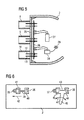
- FIG. 6 shows a front view of a cable connector 2 with connector elements 35, 36, 37, 38 in the form of connector pins, which are each surrounded by sockets and can be plugged onto the corresponding female cable connector.
- the cable plug can be secured, for example, in the inserted state against unintentional removal by a union nut or a bayonet lock.
- a locking element 39 is shown for the connector elements 35, 36, which has two cover members 40, 41, of which the cover 40 covers the connector element 36 in the position shown and blocked by it prevents touch / turn of a plugged cable connector , If the locking element 39 is displaced to the left in the direction of the arrow 42, the cover element 41 covers the plug connection element 35.
- the locking element may, for example, be displaceably guided in a guide on the cable connector 2.
- a locking element 43 which has two cover elements 44, 45 for the connector elements 37, 38, which are alternately covered and blocked during pivoting about the pivot axis 46 in the direction of the arrow 47.
- the locking elements 39, 43 may also be kept bistable, so that they are stabilized only in their respective end positions under cover of a respective connector element.
- a bus system may be provided which allows the addressing of a particular, connected via a cable to the cable connector implant, in particular a blood pump, regardless of which plug connector element on the cable connector, the cable is inserted.
- yet another implanted cable may be connected to the cable connector 2 by means of a plug connection, on the other hand connected to a power supply or communication module, which is directly under the Skin of a patient is arranged and percutaneously over fields and / or waves allows an energy or information transmission.
- each cable connected to the cable connector can be connected at its end facing away from the cable connector with one or more parallel, further cables in the sense of cascading.
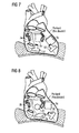
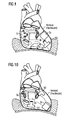
- FIGS. 7 to 12 each show advantageous possibilities for using a cable connector in cooperation with two heart support pumps, each having a projecting into the left or right ventricle heart stump.
- the cable connector is advantageously connected in each case with supply cables of the two pumps, which are connected to the cable connector by means of plug connections.
- the cable connector can advantageously be arranged directly on the heart, for example in contact with the pericardium, advantageously also inside the pericardial sac. This is particularly beneficial if the heart is already reduced by a dysfunction.
- the cable connector can advantageously be fastened to the pericardial sac, for example sewn thereto.
- the cable connector should have a sufficient distance to the cardiac assistance pumps.
Landscapes
- Health & Medical Sciences (AREA)
- Heart & Thoracic Surgery (AREA)
- Engineering & Computer Science (AREA)
- Cardiology (AREA)
- Biomedical Technology (AREA)
- Anesthesiology (AREA)
- Mechanical Engineering (AREA)
- Hematology (AREA)
- Life Sciences & Earth Sciences (AREA)
- Animal Behavior & Ethology (AREA)
- General Health & Medical Sciences (AREA)
- Public Health (AREA)
- Veterinary Medicine (AREA)
- External Artificial Organs (AREA)
- Prostheses (AREA)
Priority Applications (4)
| Application Number | Priority Date | Filing Date | Title |
|---|---|---|---|
| EP13162255.7A EP2787581A1 (fr) | 2013-04-04 | 2013-04-04 | Connecteur implantable |
| US14/782,245 US20160030652A1 (en) | 2013-04-04 | 2014-04-04 | Implantable Cable-Connecting Device |
| DE112014001602.0T DE112014001602A5 (de) | 2013-04-04 | 2014-04-04 | Implantierbare Kabelverbindungseinrichtung |
| PCT/EP2014/056775 WO2014161978A1 (fr) | 2013-04-04 | 2014-04-04 | Dispositif de connexion de câble implantable |
Applications Claiming Priority (1)
| Application Number | Priority Date | Filing Date | Title |
|---|---|---|---|
| EP13162255.7A EP2787581A1 (fr) | 2013-04-04 | 2013-04-04 | Connecteur implantable |
Publications (1)
| Publication Number | Publication Date |
|---|---|
| EP2787581A1 true EP2787581A1 (fr) | 2014-10-08 |
Family
ID=48092705
Family Applications (1)
| Application Number | Title | Priority Date | Filing Date |
|---|---|---|---|
| EP13162255.7A Withdrawn EP2787581A1 (fr) | 2013-04-04 | 2013-04-04 | Connecteur implantable |
Country Status (4)
| Country | Link |
|---|---|
| US (1) | US20160030652A1 (fr) |
| EP (1) | EP2787581A1 (fr) |
| DE (1) | DE112014001602A5 (fr) |
| WO (1) | WO2014161978A1 (fr) |
Cited By (1)
| Publication number | Priority date | Publication date | Assignee | Title |
|---|---|---|---|---|
| EP3936186A1 (fr) * | 2020-07-07 | 2022-01-12 | Maxon International AG | Raccordement électrique pour une unité d'actionneur |
Families Citing this family (8)
| Publication number | Priority date | Publication date | Assignee | Title |
|---|---|---|---|---|
| DE102013208038B4 (de) | 2013-05-02 | 2016-09-08 | Michael Siegenthaler | Katheterbasierendes Herzunterstützungssystem |
| EP3299044B1 (fr) | 2016-09-22 | 2020-12-02 | Berlin Heart GmbH | Instrument médical |
| TWI590753B (zh) * | 2016-11-02 | 2017-07-01 | 和碩聯合科技股份有限公司 | 引腳包覆裝置及應用其之雙向光學組裝裝置 |
| EP3615104A1 (fr) * | 2017-04-28 | 2020-03-04 | Tc1 Llc | Adaptateur de patient pour câble de câble de transmission et méthodes |
| DE102017213469A1 (de) * | 2017-08-03 | 2019-02-07 | Robert Bosch Gmbh | Vorrichtung zur Verbindung mit einem Kabel eines Implantats sowie zugehöriges System |
| EP3922299A1 (fr) * | 2020-06-11 | 2021-12-15 | Berlin Heart GmbH | Système de connexion destiné au transfert d'énergie et/ou de données depuis et/ou vers une pompe à sang implantable et système d'assistance cardiaque |
| WO2025147778A1 (fr) * | 2024-01-11 | 2025-07-17 | Puzzle Medical Devices Inc. | Connecteurs, fil médical de connexion et procédés associés |
| CN120473780A (zh) * | 2024-04-30 | 2025-08-12 | 深圳核心医疗科技股份有限公司 | 转接器、连接组件及心室辅助系统 |
Citations (4)
| Publication number | Priority date | Publication date | Assignee | Title |
|---|---|---|---|---|
| US20040034392A1 (en) * | 2002-08-16 | 2004-02-19 | Cardiac Pacemakers, Inc. | Connector module replacement for implantable medical stimulators |
| US20080208267A1 (en) * | 2007-02-26 | 2008-08-28 | Medtronic, Inc. | Implantable bifurcated neurostimulator adapters |
| US20110160516A1 (en) * | 2009-12-30 | 2011-06-30 | Thoratec Corporation | Mobility-Enhancing Blood Pump System |
| WO2011156391A2 (fr) | 2010-06-07 | 2011-12-15 | Thoratec Corporation | Câble percutané bi-ventriculaire |
Family Cites Families (7)
| Publication number | Priority date | Publication date | Assignee | Title |
|---|---|---|---|---|
| US5366496A (en) * | 1993-04-01 | 1994-11-22 | Cardiac Pacemakers, Inc. | Subcutaneous shunted coil electrode |
| US6486407B1 (en) * | 2001-06-14 | 2002-11-26 | Trident Design Llc | Power strip with adjustable outlets |
| US8152035B2 (en) * | 2005-07-12 | 2012-04-10 | Thoratec Corporation | Restraining device for a percutaneous lead assembly |
| US7347746B1 (en) * | 2006-10-27 | 2008-03-25 | Boston Scientific Neuromodulation Corporation | Receptacle connector assembly |
| US8162684B1 (en) * | 2008-08-07 | 2012-04-24 | Jerzy Roman Sochor | Implantable connector with contact-containing feedthrough pins |
| US9480551B2 (en) * | 2007-10-11 | 2016-11-01 | Peter Forsell | Implantable tissue connector |
| WO2012012552A1 (fr) * | 2010-07-22 | 2012-01-26 | Thoratec Corporation | Commande de pompes sanguines implantées |
-
2013
- 2013-04-04 EP EP13162255.7A patent/EP2787581A1/fr not_active Withdrawn
-
2014
- 2014-04-04 DE DE112014001602.0T patent/DE112014001602A5/de not_active Withdrawn
- 2014-04-04 US US14/782,245 patent/US20160030652A1/en not_active Abandoned
- 2014-04-04 WO PCT/EP2014/056775 patent/WO2014161978A1/fr not_active Ceased
Patent Citations (4)
| Publication number | Priority date | Publication date | Assignee | Title |
|---|---|---|---|---|
| US20040034392A1 (en) * | 2002-08-16 | 2004-02-19 | Cardiac Pacemakers, Inc. | Connector module replacement for implantable medical stimulators |
| US20080208267A1 (en) * | 2007-02-26 | 2008-08-28 | Medtronic, Inc. | Implantable bifurcated neurostimulator adapters |
| US20110160516A1 (en) * | 2009-12-30 | 2011-06-30 | Thoratec Corporation | Mobility-Enhancing Blood Pump System |
| WO2011156391A2 (fr) | 2010-06-07 | 2011-12-15 | Thoratec Corporation | Câble percutané bi-ventriculaire |
Cited By (4)
| Publication number | Priority date | Publication date | Assignee | Title |
|---|---|---|---|---|
| EP3936186A1 (fr) * | 2020-07-07 | 2022-01-12 | Maxon International AG | Raccordement électrique pour une unité d'actionneur |
| WO2022008178A1 (fr) * | 2020-07-07 | 2022-01-13 | Maxon International Ag | Connexion électrique pour une unité d'actionneur |
| EP4287419A3 (fr) * | 2020-07-07 | 2024-02-14 | Maxon International AG | Raccordement électrique pour une unité d'actionneur |
| US12463368B2 (en) | 2020-07-07 | 2025-11-04 | Maxon International Ag | Electrical connection for an actuator unit |
Also Published As
| Publication number | Publication date |
|---|---|
| WO2014161978A1 (fr) | 2014-10-09 |
| US20160030652A1 (en) | 2016-02-04 |
| DE112014001602A5 (de) | 2016-01-21 |
Similar Documents
| Publication | Publication Date | Title |
|---|---|---|
| EP2787581A1 (fr) | Connecteur implantable | |
| EP1847292B1 (fr) | Dispositif médical implantable actif doté d'au moins deux fonctions diagnostiques et/ou thérapeutiques | |
| DE2309204C2 (de) | Steckvorrichtung für den Anschluß einer Anzahl von Zuleitungen für Herzelektroden an einen Herzschrittmacher | |
| EP2130566B1 (fr) | Implant allongé doté d'un couplage d'énergie externe | |
| DE602004009585T2 (de) | Verbindungsstücke zur verbindung einer leitung mit einem implantierbaren medizinischen gerät | |
| EP2111895B1 (fr) | Boîtier de connexion pour un implant électromédical | |
| DE19818505A1 (de) | Medizinischer Leitungsadapter, Verfahren zum Herstellen desselben sowie zum Herstellen einer schnellen elektrischen Verbindung | |
| DE69329771T2 (de) | Herzschrittmacher dessen Austausch schnell und sicher ohne Reizungsunterbrechung durchgeführt werden kann | |
| DE60114291T2 (de) | Vorrichtung zum Implantieren von einer Herzstimulationsleitung in Koronargefässen | |
| EP1182978A1 (fr) | Clou d'osteosynthese intramedullaire actif destine a l'ecartement de parties d'os | |
| EP3380131A1 (fr) | Système de pompe à fluide implantable | |
| EP2140909A1 (fr) | Implant médical | |
| EP2564889A1 (fr) | Aide à l'introduction d'un fil de guidage | |
| EP3630266B1 (fr) | Adaptateur électro-médical, électrode électro-médicale et émetteur d'impulsions électro-médical | |
| EP3090767A1 (fr) | Dispositif de pompe cardiaque et système de dispositif de pompe cardiaque | |
| WO2021249721A1 (fr) | Système de connexion pour transmettre de l'énergie et/ou des données depuis et/ou vers une pompe à sang implantable, et dispositif d'assistance ventriculaire | |
| EP3416577A1 (fr) | Prise multiple pour appareil chirurgical, générateur haute fréquence électrochirurgical, fiche pour appareil électrochirurgical et système électrochirurgical | |
| DE102004062398B4 (de) | Intravenöse Herzschrittmacherelektrode | |
| EP4171728B1 (fr) | Kit d'assistance médicale | |
| WO2016177836A1 (fr) | Dispositif de pompe cardiaque et système à dispositif de pompe cardiaque | |
| EP4454696B1 (fr) | Dispositif de commande pour pompe à sang | |
| DE202023106883U1 (de) | Implantierbares medizinisches Gerät | |
| WO2015139839A1 (fr) | Adaptateur pour le raccordement d'un transmetteur de signaux électromédical à un appareil électromédical implantable | |
| DE202011109277U1 (de) | Fixierung von Kathetern und Elektroden am Menschen | |
| DE202021102721U1 (de) | Selbstdichtender Zugentlastungsmechanismus für implantierbare Impulsgeneratoren |
Legal Events
| Date | Code | Title | Description |
|---|---|---|---|
| PUAI | Public reference made under article 153(3) epc to a published international application that has entered the european phase |
Free format text: ORIGINAL CODE: 0009012 |
|
| 17P | Request for examination filed |
Effective date: 20130404 |
|
| AK | Designated contracting states |
Kind code of ref document: A1 Designated state(s): AL AT BE BG CH CY CZ DE DK EE ES FI FR GB GR HR HU IE IS IT LI LT LU LV MC MK MT NL NO PL PT RO RS SE SI SK SM TR |
|
| AX | Request for extension of the european patent |
Extension state: BA ME |
|
| STAA | Information on the status of an ep patent application or granted ep patent |
Free format text: STATUS: THE APPLICATION IS DEEMED TO BE WITHDRAWN |
|
| 18D | Application deemed to be withdrawn |
Effective date: 20150409 |