EP2788055B1 - Spritzenträger - Google Patents
Spritzenträger Download PDFInfo
- Publication number
- EP2788055B1 EP2788055B1 EP12794996.4A EP12794996A EP2788055B1 EP 2788055 B1 EP2788055 B1 EP 2788055B1 EP 12794996 A EP12794996 A EP 12794996A EP 2788055 B1 EP2788055 B1 EP 2788055B1
- Authority
- EP
- European Patent Office
- Prior art keywords
- syringe
- syringe carrier
- sections
- carrier
- barrel
- Prior art date
- Legal status (The legal status is an assumption and is not a legal conclusion. Google has not performed a legal analysis and makes no representation as to the accuracy of the status listed.)
- Active
Links
Images


Classifications
-
- A—HUMAN NECESSITIES
- A61—MEDICAL OR VETERINARY SCIENCE; HYGIENE
- A61M—DEVICES FOR INTRODUCING MEDIA INTO, OR ONTO, THE BODY; DEVICES FOR TRANSDUCING BODY MEDIA OR FOR TAKING MEDIA FROM THE BODY; DEVICES FOR PRODUCING OR ENDING SLEEP OR STUPOR
- A61M5/00—Devices for bringing media into the body in a subcutaneous, intra-vascular or intramuscular way; Accessories therefor, e.g. filling or cleaning devices, arm-rests
- A61M5/178—Syringes
- A61M5/24—Ampoule syringes, i.e. syringes with needle for use in combination with replaceable ampoules or carpules, e.g. automatic
-
- A—HUMAN NECESSITIES
- A61—MEDICAL OR VETERINARY SCIENCE; HYGIENE
- A61M—DEVICES FOR INTRODUCING MEDIA INTO, OR ONTO, THE BODY; DEVICES FOR TRANSDUCING BODY MEDIA OR FOR TAKING MEDIA FROM THE BODY; DEVICES FOR PRODUCING OR ENDING SLEEP OR STUPOR
- A61M5/00—Devices for bringing media into the body in a subcutaneous, intra-vascular or intramuscular way; Accessories therefor, e.g. filling or cleaning devices, arm-rests
- A61M5/178—Syringes
- A61M5/31—Details
- A61M5/32—Needles; Details of needles pertaining to their connection with syringe or hub; Accessories for bringing the needle into, or holding the needle on, the body; Devices for protection of needles
- A61M5/3205—Apparatus for removing or disposing of used needles or syringes, e.g. containers; Means for protection against accidental injuries from used needles
- A61M5/321—Means for protection against accidental injuries by used needles
-
- A—HUMAN NECESSITIES
- A61—MEDICAL OR VETERINARY SCIENCE; HYGIENE
- A61M—DEVICES FOR INTRODUCING MEDIA INTO, OR ONTO, THE BODY; DEVICES FOR TRANSDUCING BODY MEDIA OR FOR TAKING MEDIA FROM THE BODY; DEVICES FOR PRODUCING OR ENDING SLEEP OR STUPOR
- A61M5/00—Devices for bringing media into the body in a subcutaneous, intra-vascular or intramuscular way; Accessories therefor, e.g. filling or cleaning devices, arm-rests
- A61M5/178—Syringes
- A61M5/24—Ampoule syringes, i.e. syringes with needle for use in combination with replaceable ampoules or carpules, e.g. automatic
- A61M2005/2403—Ampoule inserted into the ampoule holder
- A61M2005/2407—Ampoule inserted into the ampoule holder from the rear
-
- A—HUMAN NECESSITIES
- A61—MEDICAL OR VETERINARY SCIENCE; HYGIENE
- A61M—DEVICES FOR INTRODUCING MEDIA INTO, OR ONTO, THE BODY; DEVICES FOR TRANSDUCING BODY MEDIA OR FOR TAKING MEDIA FROM THE BODY; DEVICES FOR PRODUCING OR ENDING SLEEP OR STUPOR
- A61M5/00—Devices for bringing media into the body in a subcutaneous, intra-vascular or intramuscular way; Accessories therefor, e.g. filling or cleaning devices, arm-rests
- A61M5/178—Syringes
- A61M5/24—Ampoule syringes, i.e. syringes with needle for use in combination with replaceable ampoules or carpules, e.g. automatic
- A61M2005/2403—Ampoule inserted into the ampoule holder
- A61M2005/2414—Ampoule inserted into the ampoule holder from the side
-
- A—HUMAN NECESSITIES
- A61—MEDICAL OR VETERINARY SCIENCE; HYGIENE
- A61M—DEVICES FOR INTRODUCING MEDIA INTO, OR ONTO, THE BODY; DEVICES FOR TRANSDUCING BODY MEDIA OR FOR TAKING MEDIA FROM THE BODY; DEVICES FOR PRODUCING OR ENDING SLEEP OR STUPOR
- A61M5/00—Devices for bringing media into the body in a subcutaneous, intra-vascular or intramuscular way; Accessories therefor, e.g. filling or cleaning devices, arm-rests
- A61M5/178—Syringes
- A61M5/24—Ampoule syringes, i.e. syringes with needle for use in combination with replaceable ampoules or carpules, e.g. automatic
- A61M2005/2433—Ampoule fixed to ampoule holder
- A61M2005/2437—Ampoule fixed to ampoule holder by clamping means
-
- A—HUMAN NECESSITIES
- A61—MEDICAL OR VETERINARY SCIENCE; HYGIENE
- A61M—DEVICES FOR INTRODUCING MEDIA INTO, OR ONTO, THE BODY; DEVICES FOR TRANSDUCING BODY MEDIA OR FOR TAKING MEDIA FROM THE BODY; DEVICES FOR PRODUCING OR ENDING SLEEP OR STUPOR
- A61M5/00—Devices for bringing media into the body in a subcutaneous, intra-vascular or intramuscular way; Accessories therefor, e.g. filling or cleaning devices, arm-rests
- A61M5/178—Syringes
- A61M5/31—Details
-
- A—HUMAN NECESSITIES
- A61—MEDICAL OR VETERINARY SCIENCE; HYGIENE
- A61M—DEVICES FOR INTRODUCING MEDIA INTO, OR ONTO, THE BODY; DEVICES FOR TRANSDUCING BODY MEDIA OR FOR TAKING MEDIA FROM THE BODY; DEVICES FOR PRODUCING OR ENDING SLEEP OR STUPOR
- A61M5/00—Devices for bringing media into the body in a subcutaneous, intra-vascular or intramuscular way; Accessories therefor, e.g. filling or cleaning devices, arm-rests
- A61M5/178—Syringes
- A61M5/31—Details
- A61M5/32—Needles; Details of needles pertaining to their connection with syringe or hub; Accessories for bringing the needle into, or holding the needle on, the body; Devices for protection of needles
- A61M5/3202—Devices for protection of the needle before use, e.g. caps
Definitions
- the invention relates to syringe carrier.
- a pre-filled syringe is housed in a carrier which is axially movable to achieve needle penetration in an injection site and, optionally, needle withdrawal.
- a conventional carrier provides shoulders that are adapted to engage a neck on the syringe and prevent the syringe from disengaging the carrier. Because syringes are generally supplied with rigid needle shields covering the needle and those needle shields have a diameter greater than a diameter between the shoulders, a separate assembly step is required - inserting the syringe in the carrier and then attaching the rigid needle shield to the needle. Accordingly, there is a need for a syringe carrier which does not require this separate assembly step.
- US 5 078 698 A discloses a hypodermic syringe holder adapted to receive a disposable carpule and eject it in an axial direction includes a pair of pivotable jaws disposed on pivots on opposite sides of the body of the holder and a sleeve element for opening and closing the jaws slidably disposed around the body of the holder. In the downward position, the sleeve element closes the jaws around the carpule and in the upward position, the sleeve opens the jaws, permitting the carpule to be safely and consistently ejected from the holder in an axial direction.
- a syringe carrier comprises a body adapted to receive a barrel of a syringe.
- the body includes two sections having distal ends with shoulder sections adapted to engage a circumferential gap between the barrel of the syringe and a needle shield covering a needle of the syringe.
- the sections are resiliently coupled to a collar on a proximal end of the body.
- the shoulder sections deflect when engaged by the needle shield and return to a non-deflected position when disengaged by the needle shield to engage the circumferential gap between the barrel of the syringe and the needle shield.
- the sections are resiliently coupled to a collar on a distal end of the body.
- the sections deflect when engaged by the needle shield and return to a non-deflected position when disengaged by the needle shield to engage a finger flange of the syringe.
- the body includes resilient arms having additional shoulder sections adapted to engage the circumferential gap between the barrel of the syringe and a needle shield covering a needle of the syringe. The arms deflect when engaged by the needle shield and return to a non-deflected position when disengaged by the needle shield to engage the circumferential gap between the barrel of the syringe and a needle shield.
- the sections are coupled via at least one hinge and are movable between an open position and a closed position.
- a first section includes a pin adapted to engage a hole on a second section to secure the sections in the closed position.
- the sections are coupled via at least one clip and are movable between an open position and a closed position.
- the at least one clip includes a hook on a first section adapted to engage an eye on a second section to secure the sections in the closed position.
- the sections include doors hingedly coupled to the body and additional shoulder sections are formed on distal ends of the doors.
- the shoulder sections include proximally-facing contoured surfaces to accommodate a proximal portion of a neck of the syringe and distally-facing planar surfaces to abut the needle shield.
- the body includes one or more viewing windows.
- the body includes a retainer element adapted to provide an abutment surface to prevent the syringe from disengaging the syringe carrier in a proximal direction.
- the syringe 2 comprises a barrel 2.1 and a neck 2.2 which has a smaller diameter than the barrel 2.1.
- a needle 3 is mounted to the neck 2.2 and a rigid needle shield (RNS) 4 is removably arranged on the needle 3.
- RNS rigid needle shield
- a portion of the RNS may cover a portion of the neck 2.2, leaving a circumferential gap between the barrel 2.1 and the RNS 4.
- the RNS 4 has a diameter substantially equal to the diameter of the barrel 2.1.
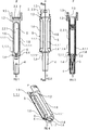
- Figures 1-4 show a first exemplary embodiment of a syringe carrier 1 according to the present in invention.
- Figure 1 is a top view of the syringe carrier 1 for supporting a syringe 2.
- Figure 2 is a lateral view of the syringe carrier of figure 1.
- Figure 3 is a longitudinal section of the syringe carrier of figure 1 in the section plane A-A.
- Figure 4 is a perspective view of the syringe carrier of figure 1 without the syringe 2.
- the syringe carrier 1 comprises an elongate body 1.1 arranged to receive the barrel 2.1.
- the body 1.1 has a cylindrical shape with an internal diameter corresponding to the diameter of the barrel 2.1.
- the body 1.1 comprises a collar 1.2 at a proximal end dimensioned to allow axial insertion of the syringe 2 into the syringe carrier 1 in a distal direction D.
- Resilient sections 1.1.1 extend distally from the collar 1.2.
- Distal ends of the sections 1.1.1 include shoulder sections 1.4 shaped as portions of a circle arranged in a transverse plane with respect to a longitudinal axis of the carrier 1.
- the shoulder sections include facing surfaces 6.
- the facing surfaces 6 When the sections 1.1.1 are in a non-deflected position, the facing surfaces 6 may abut each other, and the shoulder sections 1.4 form a circular shoulder (because the facing surfaces 6 abut each other) adapted to engage the circumferential gap between the barrel 2.1 and the RNS 4.
- the syringe 2, with RNS 4 attached to the needle 3, may be loaded into the syringe carrier 1 by sliding the syringe 2 in the distal direction D into the syringe carrier 2.
- RNS 4 abuts the shoulder sections 1.4
- additional axial force may be applied to cause the arms 1.3 to deflect radially.
- the sections 1.1.1 may return to the non-deflected position, and the shoulder sections 1.4 may engage the circumferential gap between the barrel 2.1 and the RNS 4 and prevent the syringe 2 from moving in the distal direction D relative to the syringe carrier 1.
- the proximal end 1.5 of the body 1.1 may be arranged to receive a finger flange 2.3 of the syringe 2.
- the shoulder sections 1.4 may include proximally-facing contoured surfaces to accommodate a proximal portion of the neck 2.2 of the syringe 2 and distally-facing planar surfaces to abut the RNS 4.
- viewing windows 5 may be arranged in the body 1.1 for allowing visual access to the barrel 2.1 of the syringe 2 when the syringe 2 is in the syringe carrier 2.
- the windows 5 are formed when cut-outs in the resilient sections (1.1.1) are substantially contiguous when the resilient sections (1.1.1) are in the non-deflected position (as shown in Figure 1 ).
- a projection 1.6 may be formed around each cut-out, and when the sections 1.1.1 are in the non-deflected position, the projections 1.6 may form an outline for the window 5.
- the windows 5 may be formed in the sections 1.1.1.
- Figures 5-8 show a second exemplary embodiment of a syringe carrier 1 according to the present invention.
- Figure 6 is a lateral view of the syringe carrier 1 of figure 5.
- Figure 7 is a longitudinal section of the syringe carrier 1 of figure 5 in the section plane A-A.
- Figure 8 is a perspective view of the syringe carrier of figure 5 without the syringe 2.
- the syringe carrier 1 comprises an elongate body 1.1 arranged to receive the barrel 2.1.
- the body 1.1 is comprised of two resilient sections 1.1.1 which, when together, have a cylindrical shape with an internal diameter corresponding to the diameter of the barrel 2.1.
- Distal ends of the sections 1.1.1 of the body 1.1 comprise part of a collar 1.2 dimensioned to allow axial insertion of the syringe 2 into the syringe carrier 1.
- Resilient arms 1.3 are formed in the body 1.1.
- Distal ends of the arms 1.3 include shoulder sections 1.4 shaped as portions of a circle arranged in a transverse plane with respect to a longitudinal axis of the carrier 1.
- the shoulder sections include facing surfaces 6.
- the facing surfaces 6 may abut the distal ends of the sections 1.1.1 of the body 1.1 to form a circular shoulder adapted to engage the circumferential gap between the barrel 2.1 and the RNS 4.
- the syringe 2, with RNS 4 attached to the needle 3, may be loaded into the syringe carrier 1 by sliding the syringe 2 in the distal direction D into the syringe carrier 2.
- the sections 1.1.1 may deflect radially.
- the sections 1.1.1 may return to the non-deflected position.
- the arms 1.3 may deflect until the RNS 4 bypasses the shoulder sections 1.4.
- the arms 1.3 may return to the non-deflected position, and the shoulder sections 1.4 and the collar 1.2 may engage the circumferential gap between the barrel 2.1 and the RNS 4 and prevent the syringe 2 from moving in the distal direction D relative to the syringe carrier 1.
- the proximal end 1.5 of the body 1.1 may be arranged to receive a finger flange 2.3 of the syringe 2.
- the proximal end 1.5 may also include a retainer element 1.7 which is adapted to provide an abutment surface to prevent the syringe 2 from disengaging the syringe carrier 1 in the proximal direction D.
- the shoulder sections 1.4 may include proximally-facing contoured surfaces to accommodate a proximal portion of the neck 2.2 of the syringe 2 and distally-facing planar surfaces to abut the RNS 4.
- viewing windows 5 may be arranged in the body 1.1 for allowing visual access to the barrel 2.1 of the syringe 2 when the syringe 2 is in the syringe carrier 2.
- the windows 5 are formed when cut-outs in the sections 1.1.1 are substantially contiguous when the sections 1.1.1 are in the non-deflected position (as shown in Figure 5 ).
- a projection 1.6 may be formed around each cut-out, and when the sections 1.1.1 are in the non-deflected position, the projections 1.6 may form an outline for the window 5.
- Figures 9-13 show a third exemplary embodiment of a syringe carrier 1 according to the present invention.
- Figure 9 is a top view of a third embodiment of a syringe carrier 1 for supporting a syringe 2.
- Figure 10 is a lateral view of the syringe carrier 1 of figure 9.
- Figure 11 is a longitudinal section of the syringe carrier 1 of figure 9 in the section plane A-A.
- Figure 12 is a perspective view of the syringe carrier of figure 9 without the syringe 2.
- Figure 13 is another perspective view of the syringe carrier of figure 9 .
- the syringe carrier 1 comprises an elongate body 1.1 arranged to receive the barrel 2.1.
- the body 1.1 is comprised of two sections 1.1.1 which, when together, have a cylindrical shape with an internal diameter corresponding to the diameter of the barrel 2.1.
- the sections 1.1.1 may be coupled by a side hinge which allows the section 1.1.1 to rotate relative to each other sufficient to receive the syringe 2.
- Proximal and distal ends of the sections 1.1.1 include shoulder sections 1.4 shaped as portions of a circle arranged in a transverse plane with respect to a longitudinal axis of the carrier 1.
- the shoulder sections include facing surfaces 6.
- the facing surfaces 6 When the sections 1.1.1 are in a closed position, the facing surfaces 6 may abut each other so that the shoulder sections 1.4 form circular shoulders adapted to proximally abut a finger flange 2.3 on the syringe 2 and to distally engage the circumferential gap between the barrel 2.1 and the RNS 4.
- the facing surfaces 6 of one section 1.1.1 may include holes 1.10 and the facing surfaces 6 of the other section 1.1.1 may include pins 1.11 adapted to engage (e.g., frictionally, snap-fit, etc.) the holes 1.10 to secure the sections 1.1.1 in the closed position.
- the syringe 2, with RNS 4 attached to the needle 3, may be loaded into the syringe carrier 1 by opening the sections 1.1.1 about the hinge and placing the syringe 2 in the syringe carrier 2.
- the sections 1.1.1 are closed, the pins 1.11 engage the holes 1.10, and the proximal shoulder sections 1.4 form circular shoulders adapted to proximally abut a finger flange 2.3 on the syringe 2 and the distal shoulder section s1.4 to distally engage the circumferential gap between the barrel 2.1 and the RNS 4.
- the syringe 2 is prevented from moving axially relative to the syringe carrier 1.
- the proximal end 1.5 may include a retainer element 1.7 which is adapted to provide an abutment surface to prevent the syringe 2 from disengaging the syringe carrier 1 in the proximal direction D.
- the shoulder sections 1.4 may include proximally-facing contoured surfaces to accommodate a proximal portion of the neck 2.2 of the syringe 2 and distally-facing planar surfaces to abut the RNS 4.
- viewing windows 5 may be arranged in the body 1.1 for allowing visual access to the barrel 2.1 of the syringe 2 when the syringe 2 is in the syringe carrier 2.
- the windows 5 are formed when cut-outs in the sections 1.1.1 are substantially contiguous when the sections 1.1.1 are in the closed position.
- a projection 1.6 may be formed around each cut-out, and when the sections 1.1.1 are in the non-deflected position, the projections 1.6 may form an outline for the window 5.
- Figures 14-18 show a fourth exemplary embodiment of a syringe carrier 1 according to the present invention.
- Figure 14 is a top view of a fourth embodiment of a syringe carrier 1 for supporting a syringe 2.
- Figure 15 is a lateral view of the syringe carrier 1 of figure 14.
- Figure 16 is a longitudinal section of the syringe carrier 1 of figure 14 in the section plane A-A.
- Figure 17 is a perspective view of the syringe carrier of figure 14 without the syringe 2.
- Figure 18 is another perspective view of the syringe carrier of figure 14 .
- the syringe carrier 1 comprises an elongate body 1.1 arranged to receive the barrel 2.1.
- the body 1.1 has a cylindrical shape with an internal diameter corresponding to the diameter of the barrel 2.1.
- a distal end of the body 1.1 includes a shoulder sections 1.4 shaped as a portion of a circle arranged in a transverse plane with respect to a longitudinal axis of the carrier 1, and at least one door 1.12 hingedly coupled to the body 1.1 and including a shoulder section 1.4.
- a hinge 1.9 coupling the door 1.12 to the body 1.1 may be provided on an axis parallel to the longitudinal axis of the syringe carrier 1 or on an axis transverse to the longitudinal axis of the syringe carrier 1.
- the shoulder section 1.4 includes facing surfaces 6 which abut facing surfaces 6 of the door 1.12 when the door 1.12 is in a closed position (as shown in Figure 14 ). When the door 1.12 is in the closed position, the facing surfaces 6 may abut each other so that the shoulder sections 1.4 on the body 1.1 and the door 1.12 to form a circular shoulder adapted to engage the circumferential gap between the barrel 2.1 and the RNS 4.
- the facing surfaces 6 of the door 1.12 may include holes 1.10 and the facing surfaces 6 of the body 1.1 may include pins 1.11 (or vice-versa) adapted to engage (e.g., frictionally, snap-fit, etc.) the holes 1.10 to secure the door 1.12 in the closed position.
- the syringe 2, with RNS 4 attached to the needle 3, may be loaded into the syringe carrier 1 by opening the door 1.12 and sliding the syringe 2 into the syringe carrier 1.
- the door 1.12 may be closed to engage the gap and prevent the syringe 2 from moving axially relative to the syringe carrier 1.
- the shoulder sections 1.4 may include proximally-facing contoured surfaces to accommodate a proximal portion of the neck 2.2 of the syringe 2 and distally-facing planar surfaces to abut the RNS 4.
- viewing windows may be arranged in the body 1.1 for allowing visual access to the barrel 2.1 of the syringe 2 when the syringe 2 is in the syringe carrier 2.
- the windows are formed as cut-outs.
- Figures 19-23 show a fifth exemplary embodiment of a syringe carrier 1 according to the present invention.
- Figure 19 is a top view of a fifth embodiment of a syringe carrier 1 for supporting a syringe 2.
- Figure 20 is a lateral view of the syringe carrier 1 of figure 19.
- Figure 21 is a longitudinal section of the syringe carrier 1 of figure 19 in the section plane A-A.
- Figure 22 is a perspective view of the syringe carrier of figure 19 without the syringe 2.
- Figure 23 is another perspective view of the syringe carrier of figure 19 .
- the syringe carrier 1 comprises an elongate body 1.1 arranged to receive the barrel 2.1.
- the body 1.1 is comprised of two sections 1.1.1 which, when together, have a cylindrical shape with an internal diameter corresponding to the diameter of the barrel 2.1.
- the sections 1.1.1 may be coupled together by clips.
- a clip may comprise a eye 1.14 on a first section adapted to engage a hook 1.13 on a second section.
- the eye 1.14 may have a cross-section substantially equal to the cross-section of the hook 1.13 such that the eye 1.14 and hook 1.13 engage in a snap-fit.
- Distal ends of the sections 1.1.1 include shoulder sections 1.4 shaped as portions of a circle arranged in a transverse plane with respect to a longitudinal axis of the carrier 1.
- the shoulder sections include facing surfaces 6. When the sections 1.1.1 are in a closed position, the facing surfaces 6 may abut each other so that the shoulder sections 1.4 form circular shoulders adapted engage the circumferential gap between the barrel 2.1 and the RNS 4.
- the sections 1.1.1 may be hingedly connected.
- the syringe 2, with RNS 4 attached to the needle 3, may be loaded into the syringe carrier 1 by opening the sections 1.1.1 and placing the syringe 2 in the syringe carrier 2.
- the sections 1.1.1 are closed, the eyes 1.14 engage the hooks 1.13 and the shoulder sections 1.4 engage the circumferential gap between the barrel 2.1 and the RNS 4.
- the syringe 2 is prevented from moving axially relative to the syringe carrier 1.
- the proximal end may include a retainer element which is adapted to provide an abutment surface to prevent the syringe 2 from disengaging the syringe carrier 1 in the proximal direction D.
- the shoulder sections 1.4 may include proximally-facing contoured surfaces to accommodate a proximal portion of the neck 2.2 of the syringe 2 and distally-facing planar surfaces to abut the RNS 4.
- viewing windows may be arranged in the body 1.1 for allowing visual access to the barrel 2.1 of the syringe 2 when the syringe 2 is in the syringe carrier 2.
- Figures 24-28 show a sixth exemplary embodiment of a syringe carrier 1 according to the present invention.
- Figure 24 is a top view of a sixth embodiment of a syringe carrier 1 for supporting a syringe 2.
- Figure 25 is a lateral view of the syringe carrier 1 of figure 24.
- Figure 26 is a longitudinal section of the syringe carrier 1 of figure 24 in the section plane A-A.
- Figure 27 is a perspective view of the syringe carrier of figure 24 without the syringe 2.
- Figure 28 is another perspective view of the syringe carrier of figure 24 .
- the syringe carrier 1 comprises an elongate body 1.1 arranged to receive the barrel 2.1.
- the body 1.1 has a partially cylindrical shape with an internal diameter corresponding to the diameter of the barrel 2.1.
- the body 1.1 may include a longitudinal slot (e.g., a cut-out) which is adapted to snap over the barrel 2.1 of the syringe 2.
- Proximal and distal ends of the body 1.1 include clamps 1.15, 1.16 which are adapted to retain the syringe 2 when in the syringe carrier 1.
- the distal end of the body 1 further includes shoulder sections 1.4 shaped as a portion of a circle arranged in a transverse plane with respect to a longitudinal axis of the carrier 1.
- the shoulder sections 14 form circular shoulders adapted to engage the circumferential gap between the barrel 2.1 and the RNS 4.
- the syringe 2, with RNS 4 attached to the needle 3, may be loaded into the syringe carrier 1 by pressing the barrel 2.1 against the clamps 1.15, 1.16, causing the clamps 1.15, 1.16 to deflect and widen the longitudinal slot in the body 1.1.
- the clamps 1.15, 1.16 return to their non-deflected position and retain the syringe 2 in the syringe carrier 1.
- the shoulder sections 1.4 engage the circumferential gap between the barrel 2.1 and the RNS 4.
- the proximal end may include a retainer element which is adapted to provide an abutment surface to prevent the syringe 2 from disengaging the syringe carrier 1 in the proximal direction D.
- the shoulder sections 1.4 may include proximally-facing contoured surfaces to accommodate a proximal portion of the neck 2.2 of the syringe 2 and distally-facing planar surfaces to abut the RNS 4.
- a viewing window may be arranged in the body 1.1 for allowing visual access to the barrel 2.1 of the syringe 2 when the syringe 2 is in the syringe carrier 2.
- Figures 29-33 show a seventh exemplary embodiment of a syringe carrier 1 according to the present invention.
- Figure 29 is a top view of a seventh embodiment of a syringe carrier 1 for supporting a syringe 2.
- Figure 30 is a lateral view of the syringe carrier 1 of figure 29.
- Figure 31 is a longitudinal section of the syringe carrier 1 of figure 29 in the section plane A-A.
- Figure 32 is a perspective view of the syringe carrier of figure 29 without the syringe 2.
- Figure 33 is another perspective view of the syringe carrier of figure 29 .
- the syringe carrier 1 comprises an elongate body 1.1 arranged to receive the barrel 2.1.
- the body 1.1 has a partially cylindrical shape with an internal diameter corresponding to the diameter of the barrel 2.1.
- the body 1.1 includes a collar 1.2 at its proximal end and may include a longitudinal slot (e.g., a cut-out) formed in the body 1.1 distally of the collar 1.2 which is adapted to snap over the barrel 2.1 of the syringe 2.
- a pair of groove hinges 1.17 may be formed in the body 1.1 adjacent a proximal end of the slot.
- the distal end of the body 1 includes shoulder sections 1.4 shaped as a portion of a circle arranged in a transverse plane with respect to a longitudinal axis of the carrier 1.
- the shoulder sections 14 form circular shoulders adapted to engage the circumferential gap between the barrel 2.1 and the RNS 4.
- the syringe 2, with RNS 4 attached to the needle 3, may be loaded into the syringe carrier 1 by sliding the syringe 2 through the collar 1.2 in the distal direction D.
- the body 1.1 may radially deflect (e.g., rotate) about the groove hinges 1.17.
- the RNS 4 bypasses the shoulder sections 1.4, the body 1.1 may return to its non-deflected position and retain the syringe 2 in the syringe carrier 1.
- the shoulder sections 1.4 engage the circumferential gap between the barrel 2.1 and the RNS 4.
- the syringe 2 is prevented from moving axially relative to the syringe carrier 1.
- the proximal end may include a retainer element which is adapted to provide an abutment surface to prevent the syringe 2 from disengaging the syringe carrier 1 in the proximal direction D.
- the shoulder sections 1.4 may include proximally-facing contoured surfaces to accommodate a proximal portion of the neck 2.2 of the syringe 2 and distally-facing planar surfaces to abut the RNS 4.
- a viewing window may be arranged in the body 1.1 for allowing visual access to the barrel 2.1 of the syringe 2 when the syringe 2 is in the syringe carrier 2.
- Figures 34-38 show an eighth exemplary embodiment of a syringe carrier 1 according to the present invention.
- Figure 34 is a top view of an eighth embodiment of a syringe carrier 1 for supporting a syringe 2.
- Figure 35 is a lateral view of the syringe carrier 1 of figure 34.
- Figure 36 is a longitudinal section of the syringe carrier 1 of figure 34 in the section plane A-A.
- Figure 37 is a perspective view of the syringe carrier of figure 34 without the syringe 2.
- Figure 38 is another perspective view of the syringe carrier of figure 34 .
- the syringe carrier 1 comprises an elongate body 1.1 arranged to receive the barrel 2.1.
- the body 1.1 has a cylindrical shape with an annular groove 1.19 adjacent its distal end which is adapted to engage a circlip 8.
- the circlip 8 may engage the circumferential gap between the barrel 1.2 and the RNS 4.
- the syringe 2, with RNS 4 attached to the needle 3 and the circlip 8 attached to the syringe 2, may be loaded into the syringe carrier 1 by sliding the syringe 2 into the syringe carrier 1 in the distal direction D.
- an outer diameter of the circlip 8 may be substantially equal to a diameter of the body 1.1.
- the circlip 8 may then expand to the non-deflected position and retain the syringe 2 in an axial position relative to the syringe carrier 1. That is, the circlip 8 may engage the annular groove 1.19 and the circumferential gap between the barrel 2.1 and the RNS 4. Thus, the syringe 2 is prevented from moving axially relative to the syringe carrier 1.
- the proximal end may include a retainer element which is adapted to provide an abutment surface to prevent the syringe 2 from disengaging the syringe carrier 1 in the proximal direction D.
- the shoulder sections 1.4 may include proximally-facing contoured surfaces to accommodate a proximal portion of the neck 2.2 of the syringe 2 and distally-facing planar surfaces to abut the RNS 4.
- a viewing window may be arranged in the body 1.1 for allowing visual access to the barrel 2.1 of the syringe 2 when the syringe 2 is in the syringe carrier 2.
- Figures 39-43 show a ninth exemplary embodiment of a syringe carrier 1 according to the present invention.
- Figure 39 is a top view of a ninth embodiment of a syringe carrier 1 for supporting a syringe 2.
- Figure 40 is a lateral view of the syringe carrier 1 of figure 39.
- Figure 41 is a longitudinal section of the syringe carrier 1 of figure 39 in the section plane A-A.
- Figure 42 is a perspective view of the syringe carrier of figure 39 without the syringe 2.
- Figure 43 is another perspective view of the syringe carrier of figure 39 .
- the syringe carrier 1 comprises an elongate body 1.1 arranged to receive the barrel 2.1.
- the body 1.1 has a cylindrical shape with an annular groove 1.19 having at least one aperture 1.20 adjacent its distal end which is adapted to engage a circlip 8.
- the syringe 2, with RNS 4 attached to the needle 3, may be loaded into the syringe carrier 1 by sliding the syringe 2 into the syringe carrier.1 in the distal direction D.
- the circlip 8 may be coupled to the body 1.1 and engage the apertures 1.20. By extending inwardly through the apertures, the circlip 8 may be coupled to the outside of the body 1.1 but engage the circumferential gap between the barrel 2.1 and the RNS 4.
- the engagement between the circlip 8 and the apertures 1.20 prevents the circlip 8 from translating relative to the body 1.1, and the engagement between the circlip 8 and the circumferential gap prevents the syringe 2 from moving axially relative to the syringe carrier 1.
- the proximal end may include a retainer element which is adapted to provide an abutment surface to prevent the syringe 2 from disengaging the syringe carrier 1 in the proximal direction D.
- the shoulder sections 1.4 may include proximally-facing contoured surfaces to accommodate a proximal portion of the neck 2.2 of the syringe 2 and distally-facing planar surfaces to abut the RNS 4.
- a viewing window may be arranged in the body 1.1 for allowing visual access to the barrel 2.1 of the syringe 2 when the syringe 2 is in the syringe carrier 2.
- Figures 44-48 show a tenth exemplary embodiment of a syringe carrier 1 and a tool 9 for inserting a syringe 2 into the syringe carrier 1 according to the present invention.
- the syringe carrier 1 comprises an elongate body 1.1 arranged to receive the barrel 2.1.
- the body 1.1 has an enlarged portion 1.21 on its distal end.
- the body 1.1 has cylindrical shape with a first diameter and the enlarged portion 1.21 has a second diameter, larger than the first diameter.
- the enlarged portion 1.21 has one or more resilient barbs 1.22 extending toward a longitudinal axis of the body 1.1 and angled toward a proximal end of the body 1.1.
- the syringe 2, with RNS 4 attached to the needle 3, may be loaded into the syringe carrier 1 by inserting the tool 9 into the enlarged portion 1.21 of the syringe carrier 1.
- the tool 9 may be a cylinder having an open end adapted to receive the RNS 4.
- the tool 9 may have a third diameter substantially equal to the second diameter.
- the tool 9 engages and deflects the resilient barbs 1.22.
- the RNS 4 can pass the barbs 1.22 in the distal direction D and extend from a distal opening of the body 1.1.
- the tool 9 may be removed and the barbs 1.22 may engage the circumferential gap between the barrel 2.1 and the RNS 4 to prevent the syringe 2 from moving axially relative to the syringe carrier 1.
- the proximal end may include a retainer element which is adapted to provide an abutment surface to prevent the syringe 2 from disengaging the syringe carrier 1 in the proximal direction D.
- the barbs 1.22 may include proximally-facing contoured surfaces to accommodate a proximal portion of the neck 2.2 of the syringe 2 and distally-facing planar surfaces to abut the RNS 4.
- a viewing window may be arranged in the body 1.1 for allowing visual access to the barrel 2.1 of the syringe 2 when the syringe 2 is in the syringe carrier 2.
Landscapes
- Health & Medical Sciences (AREA)
- Engineering & Computer Science (AREA)
- Hematology (AREA)
- Anesthesiology (AREA)
- Biomedical Technology (AREA)
- Heart & Thoracic Surgery (AREA)
- Vascular Medicine (AREA)
- Life Sciences & Earth Sciences (AREA)
- Animal Behavior & Ethology (AREA)
- General Health & Medical Sciences (AREA)
- Public Health (AREA)
- Veterinary Medicine (AREA)
- Environmental & Geological Engineering (AREA)
- Infusion, Injection, And Reservoir Apparatuses (AREA)
Claims (7)
- Spritzenträger (1), umfassend:einen Körper (1.1), der zur Aufnahme eines Zylinders (2.1) einer Spritze (2) geeignet ist, wobei der Körper (1.1) zwei Abschnitte (1.1.1) aufweist, die distale Enden mit Schulterabschnitten (1.4) haben, wobei die Schulterabschnitte (1.4) geeignet sind, einen Umfangsspalt zwischen dem Zylinder (2.1) der Spritze (2) und einem Nadelschutz (4), der eine Nadel (3) der Spritze (2) abdeckt, in Eingriff zu nehmen, um zu verhindern, dass sich die Spritze (2) in einer distalen Richtung (D) bezüglich des Spritzenträgers (1) bewegt, dadurch gekennzeichnet, dass die Abschnitte (1.1.1) federnd an einen Bund (1.2) an einem proximalen Ende des Körpers (1.1) gekoppelt sind, wobei die Schulterabschnitte (1.4) auslenken, wenn sie vom Nadelschutz (4) in Eingriff genommen werden, und zu einer nicht ausgelenkten Position zurückkehren, wenn sie mit dem Nadelschutz (4) außer Eingriff kommen, um den Umfangsspalt zwischen dem Zylinder (2.1) der Spritze (2) und dem Nadelschutz (4) in Eingriff zu nehmen.
- Spritzenträger (1) nach einem der vorhergehenden Ansprüche, wobei die Schulterabschnitte (1.4) proximal ausgerichtete konturierte Flächen aufweisen, um einen proximalen Abschnitt eines Halses (2.2) der Spritze (2) aufzunehmen, sowie distal ausgerichtete planare Flächen, um an den Nadelschutz (4) anzuschlagen.
- Spritzenträger (1) nach einem der vorhergehenden Ansprüche, wobei der Körper (1.1) ein oder mehrere Sichtfenster (5) aufweist.
- Spritzenträger (1) nach einem der vorhergehenden Ansprüche, wobei der Körper (1.1) ein Halterelement aufweist, das geeignet ist, eine Anschlagfläche bereitzustellen, um zu verhindern, dass die Spritze (2) sich vom Spritzenträger (1) in einer proximalen Richtung (P) löst.
- Spritzenträger (1) nach Anspruch 3, wobei das eine oder die mehreren Sichtfenster (5) ausgebildet sind, wenn Ausschnitte in den federnden Abschnitten (1.1.1) im Wesentlichen angrenzend sind, wenn die federnden Abschnitte (1.1.1) in der nicht ausgelenkten Position sind.
- Spritzenträger (1) nach Anspruch 5, wobei um jeden Ausschnitt herum ein Vorsprung (1.6) gebildet ist und die Vorsprünge (1.6) einen Umriss für das Fenster (5) bilden, wenn die Abschnitte (1.1.1) in der nicht ausgelenkten Position sind.
- Spritzenträger (1) nach einem der Ansprüche 3 oder 4, wobei die Fenster (5) in den Abschnitten (1.1.1) ausgebildet sind.
Priority Applications (8)
| Application Number | Priority Date | Filing Date | Title |
|---|---|---|---|
| EP22167268.6A EP4043051A1 (de) | 2011-12-08 | 2012-12-05 | Spritzenträger |
| EP22167274.4A EP4043052A1 (de) | 2011-12-08 | 2012-12-05 | Spritzenträger |
| EP16195290.8A EP3153196B1 (de) | 2011-12-08 | 2012-12-05 | Spritzenträger |
| EP16195292.4A EP3153197B1 (de) | 2011-12-08 | 2012-12-05 | Spritzenträger |
| EP12794996.4A EP2788055B1 (de) | 2011-12-08 | 2012-12-05 | Spritzenträger |
| PL12794996T PL2788055T3 (pl) | 2011-12-08 | 2012-12-05 | Nośnik strzykawki |
| DK16195290.8T DK3153196T3 (da) | 2011-12-08 | 2012-12-05 | Sprøjteholder |
| DK16195292.4T DK3153197T3 (da) | 2011-12-08 | 2012-12-05 | Sprøjteholder |
Applications Claiming Priority (3)
| Application Number | Priority Date | Filing Date | Title |
|---|---|---|---|
| EP11192585.5A EP2601992A1 (de) | 2011-12-08 | 2011-12-08 | Spritzenträger |
| PCT/EP2012/074466 WO2013083613A1 (en) | 2011-12-08 | 2012-12-05 | Syringe carrier |
| EP12794996.4A EP2788055B1 (de) | 2011-12-08 | 2012-12-05 | Spritzenträger |
Related Child Applications (6)
| Application Number | Title | Priority Date | Filing Date |
|---|---|---|---|
| EP22167268.6A Division EP4043051A1 (de) | 2011-12-08 | 2012-12-05 | Spritzenträger |
| EP16195292.4A Division EP3153197B1 (de) | 2011-12-08 | 2012-12-05 | Spritzenträger |
| EP16195292.4A Division-Into EP3153197B1 (de) | 2011-12-08 | 2012-12-05 | Spritzenträger |
| EP16195290.8A Division EP3153196B1 (de) | 2011-12-08 | 2012-12-05 | Spritzenträger |
| EP16195290.8A Division-Into EP3153196B1 (de) | 2011-12-08 | 2012-12-05 | Spritzenträger |
| EP22167274.4A Division EP4043052A1 (de) | 2011-12-08 | 2012-12-05 | Spritzenträger |
Publications (2)
| Publication Number | Publication Date |
|---|---|
| EP2788055A1 EP2788055A1 (de) | 2014-10-15 |
| EP2788055B1 true EP2788055B1 (de) | 2017-02-01 |
Family
ID=47278865
Family Applications (6)
| Application Number | Title | Priority Date | Filing Date |
|---|---|---|---|
| EP11192585.5A Ceased EP2601992A1 (de) | 2011-12-08 | 2011-12-08 | Spritzenträger |
| EP22167274.4A Pending EP4043052A1 (de) | 2011-12-08 | 2012-12-05 | Spritzenträger |
| EP16195292.4A Active EP3153197B1 (de) | 2011-12-08 | 2012-12-05 | Spritzenträger |
| EP16195290.8A Active EP3153196B1 (de) | 2011-12-08 | 2012-12-05 | Spritzenträger |
| EP12794996.4A Active EP2788055B1 (de) | 2011-12-08 | 2012-12-05 | Spritzenträger |
| EP22167268.6A Pending EP4043051A1 (de) | 2011-12-08 | 2012-12-05 | Spritzenträger |
Family Applications Before (4)
| Application Number | Title | Priority Date | Filing Date |
|---|---|---|---|
| EP11192585.5A Ceased EP2601992A1 (de) | 2011-12-08 | 2011-12-08 | Spritzenträger |
| EP22167274.4A Pending EP4043052A1 (de) | 2011-12-08 | 2012-12-05 | Spritzenträger |
| EP16195292.4A Active EP3153197B1 (de) | 2011-12-08 | 2012-12-05 | Spritzenträger |
| EP16195290.8A Active EP3153196B1 (de) | 2011-12-08 | 2012-12-05 | Spritzenträger |
Family Applications After (1)
| Application Number | Title | Priority Date | Filing Date |
|---|---|---|---|
| EP22167268.6A Pending EP4043051A1 (de) | 2011-12-08 | 2012-12-05 | Spritzenträger |
Country Status (14)
| Country | Link |
|---|---|
| US (17) | US10434258B2 (de) |
| EP (6) | EP2601992A1 (de) |
| JP (1) | JP6096206B2 (de) |
| KR (1) | KR20140105525A (de) |
| AU (1) | AU2012347359B2 (de) |
| BR (1) | BR112014013780A2 (de) |
| DK (3) | DK3153197T3 (de) |
| ES (1) | ES2623256T3 (de) |
| HU (1) | HUE032673T2 (de) |
| IL (1) | IL232989A0 (de) |
| MX (1) | MX2014006847A (de) |
| PL (1) | PL2788055T3 (de) |
| RU (1) | RU2618900C2 (de) |
| WO (1) | WO2013083613A1 (de) |
Cited By (3)
| Publication number | Priority date | Publication date | Assignee | Title |
|---|---|---|---|---|
| US12208245B2 (en) | 2019-09-30 | 2025-01-28 | Amgen Inc. | Drug delivery device |
| US12599722B2 (en) | 2020-04-21 | 2026-04-14 | Shl Medical Ag | Syringe holder |
| US12611507B2 (en) | 2021-03-10 | 2026-04-28 | Amgen Inc. | Drug delivery device, subassembly for drug delivery device, syringe holder, and method of assembly |
Families Citing this family (27)
| Publication number | Priority date | Publication date | Assignee | Title |
|---|---|---|---|---|
| US20070202186A1 (en) | 2006-02-22 | 2007-08-30 | Iscience Interventional Corporation | Apparatus and formulations for suprachoroidal drug delivery |
| US8197435B2 (en) | 2006-05-02 | 2012-06-12 | Emory University | Methods and devices for drug delivery to ocular tissue using microneedle |
| JP5996544B2 (ja) | 2010-10-15 | 2016-09-21 | クリアサイド・バイオメディカル・インコーポレーテッドClearside Biomedical Incorporated | 眼球アクセス用装置 |
| CN103491998B (zh) * | 2011-01-24 | 2015-11-25 | 爱康医学农业合作协会有限公司 | 注射器 |
| EP2601989A1 (de) * | 2011-12-08 | 2013-06-12 | Sanofi-Aventis Deutschland GmbH | Spritzenträger |
| EP2601992A1 (de) | 2011-12-08 | 2013-06-12 | Sanofi-Aventis Deutschland GmbH | Spritzenträger |
| KR101924310B1 (ko) | 2011-12-15 | 2018-11-30 | 에스에이치엘 그룹 에이비 | 자동 주입 장치 |
| MX373894B (es) | 2012-11-08 | 2020-07-09 | Clearside Biomedical Inc | Métodos y dispositivos para el tratamiento de trastornos oculares en sujetos humanos. |
| EP2777684A1 (de) | 2013-03-14 | 2014-09-17 | Sanofi-Aventis Deutschland GmbH | Medikamentenbehälterträger und -adapter |
| BR112015027762A2 (pt) | 2013-05-03 | 2017-08-29 | Clearside Biomedical Inc | Aparelho e métodos para injeção ocular |
| WO2014197317A1 (en) | 2013-06-03 | 2014-12-11 | Clearside Biomedical, Inc. | Apparatus and methods for drug delivery using multiple reservoirs |
| EP3157598A4 (de) | 2014-06-20 | 2018-05-16 | Clearside Biomedical, Inc. | Kanüle mit veränderlichem durchmesser und verfahren zur steuerung der einsatztiefe zur medikamentenabgabe |
| ES2886553T3 (es) * | 2014-08-10 | 2021-12-20 | Antares Pharma Inc | Un amortiguador de jeringa para su uso en un dispositivo de inyección |
| USD750223S1 (en) | 2014-10-14 | 2016-02-23 | Clearside Biomedical, Inc. | Medical injector for ocular injection |
| WO2016131954A1 (en) | 2015-02-20 | 2016-08-25 | Novo Nordisk A/S | Needle unit for drug delivery device |
| TW201705994A (zh) | 2015-06-03 | 2017-02-16 | 賽諾菲阿凡提斯德意志有限公司 | 自動注射器及組裝方法 |
| TW201700117A (zh) * | 2015-06-03 | 2017-01-01 | 賽諾菲阿凡提斯德意志有限公司 | 用於自動注射器的注射筒托架和組裝方法 |
| TW201707738A (zh) | 2015-06-03 | 2017-03-01 | 賽諾菲阿凡提斯德意志有限公司 | 注射器支架及自動注射器(二) |
| US10390901B2 (en) | 2016-02-10 | 2019-08-27 | Clearside Biomedical, Inc. | Ocular injection kit, packaging, and methods of use |
| EP3452165A1 (de) | 2016-05-02 | 2019-03-13 | Clearside Biomedical, Inc. | Systeme und verfahren zur verabreichung eines augenmedikaments |
| IL305537B2 (en) | 2016-08-12 | 2025-02-01 | Clearside Biomedical Inc | Devices and methods for adjusting the insertion depth of a needle for administering a drug |
| CN110267693B (zh) * | 2017-02-06 | 2022-04-19 | 赛诺菲-安万特德国有限公司 | 用于具有锁定功能的笔式注射装置的组装嵌套件 |
| US12090294B2 (en) | 2017-05-02 | 2024-09-17 | Georgia Tech Research Corporation | Targeted drug delivery methods using a microneedle |
| EP4119172B1 (de) | 2019-03-15 | 2024-10-09 | Eli Lilly and Company | Automatisches injektionssystem |
| EP4291264B1 (de) * | 2021-02-15 | 2026-04-08 | SHL Medical AG | Spritzenträger |
| WO2023187495A1 (en) * | 2022-03-30 | 2023-10-05 | Janssen Biotech, Inc. | Shell for small vial to fit into injector or cap remover |
| WO2025087700A1 (en) * | 2023-10-23 | 2025-05-01 | Novo Nordisk A/S | An injection device with support ribs for supporting a glass cartridge |
Family Cites Families (162)
| Publication number | Priority date | Publication date | Assignee | Title |
|---|---|---|---|---|
| GB407109A (en) * | 1932-01-19 | 1934-03-15 | Erwin Rippstein | Improvements in or relating to syringes for subcutaneous injection |
| GB829724A (en) | 1957-10-17 | 1960-03-02 | Hoechst Ag | Holder for an injection syringe |
| US3076455A (en) | 1958-12-19 | 1963-02-05 | Robert K Mcconnaughey | Holder for hypodermic syringe cartridges |
| US3026873A (en) | 1959-03-06 | 1962-03-27 | Pfizer & Co C | Aspirating hypodermic syringe holder |
| US3144178A (en) * | 1962-03-12 | 1964-08-11 | Stanley J Sarnoff | Cartridge holder |
| GB1122592A (en) | 1965-05-19 | 1968-08-07 | Franz Wantoch | Improvements in or relating to hypodermic syringes |
| US3880163A (en) | 1973-10-26 | 1975-04-29 | Jack H Ritterskamp | Medicinal syringe actuating device |
| US4563175A (en) | 1983-12-19 | 1986-01-07 | Lafond Margaret | Multiple syringe pump |
| US4838857A (en) | 1985-05-29 | 1989-06-13 | Becton, Dickinson And Company | Medical infusion device |
| US4643724A (en) | 1985-12-16 | 1987-02-17 | Alcon Laboratories, Inc. | Syringe holder |
| US4655751A (en) * | 1986-02-14 | 1987-04-07 | Harbaugh John T | Liquid dispensing and receiving syringe |
| US4735311A (en) | 1986-04-09 | 1988-04-05 | The West Company | Needle shield assembly |
| US4973318A (en) | 1988-02-10 | 1990-11-27 | D.C.P. Af 1988 A/S | Disposable syringe |
| US4820277A (en) | 1988-02-16 | 1989-04-11 | Norelli Robert A | Safety cover for syringe needles |
| US4931040A (en) * | 1988-04-13 | 1990-06-05 | Habley Medical Technology | Safety syringe having a combination needle cannula and articulating hub for retracting said cannula into a medication carpule |
| US4871355A (en) * | 1988-05-17 | 1989-10-03 | Steven Kikkawa | Injury resistant needle and blood collection tube holder |
| US5169392A (en) * | 1988-06-28 | 1992-12-08 | Sherwood Medical Company | Combined syringe and needle shield and method of manufacture |
| US4997422A (en) | 1989-01-31 | 1991-03-05 | Chow Peter P | Hypodermic syringe with needle shield |
| US4946447A (en) | 1989-02-14 | 1990-08-07 | Hardcastle Samuel L | Protective cover for hypodermic needle |
| US5085641A (en) | 1989-07-17 | 1992-02-04 | Survival Technology, Inc. | Conveniently carried frequent use auto-injector with improved cap structure |
| US5282793A (en) | 1989-10-02 | 1994-02-01 | Larson Eldon E | Syringe holder and applicator |
| US4990142A (en) | 1989-10-23 | 1991-02-05 | Gte Products Corporation | Hypodermic syringe |
| US4964866A (en) | 1989-11-22 | 1990-10-23 | Becton, Dickinson And Company | Needle sheath assembly |
| EP0467173B1 (de) | 1990-07-19 | 1995-11-08 | Nardino Righi | Sicherheitsspritze zum einmaligen Gebrauch |
| US5350367A (en) * | 1990-11-06 | 1994-09-27 | Sterling Winthrop Inc. | Snap together hypodermic syringe holder |
| US5078698A (en) * | 1991-02-19 | 1992-01-07 | Sterling Drug Inc. | Axial eject hypodermic syringe holder |
| EP0518416A1 (de) | 1991-06-13 | 1992-12-16 | Duphar International Research B.V | Injektionsvorrichtung |
| EP0525525B1 (de) | 1991-07-24 | 1995-05-03 | Medico Development Investment Company | Injektor |
| US5322511A (en) | 1992-04-21 | 1994-06-21 | Sterling Winthrop Inc. | Portable hand-held power injector |
| US5383858B1 (en) | 1992-08-17 | 1996-10-29 | Medrad Inc | Front-loading medical injector and syringe for use therewith |
| US5320609A (en) | 1992-12-07 | 1994-06-14 | Habley Medical Technology Corporation | Automatic pharmaceutical dispensing syringe |
| US5290255A (en) | 1993-02-02 | 1994-03-01 | Vallelunga Anthony J | Apparatus for shielding a syringe needle |
| US5451214A (en) * | 1993-03-22 | 1995-09-19 | Hajishoreh; Kaveh-Karimi | Syringe apparatus |
| US5599309A (en) | 1993-03-24 | 1997-02-04 | Owen Mumford Limited | Injection devices |
| US5344407A (en) * | 1993-05-04 | 1994-09-06 | Ryan Dana W | Safety holder for pre-filled disposable syringe cartridge |
| US5383863A (en) | 1993-11-15 | 1995-01-24 | Mardones; Nestor E. | Attachment for maximum safety of hypodermic syringes |
| US5356395A (en) | 1993-12-14 | 1994-10-18 | Chen Shih Shuan | Safety syringe shield |
| US5368578A (en) * | 1994-03-10 | 1994-11-29 | Sterling Winthrop Inc. | Hypodermic syringe holder |
| US5722951A (en) | 1994-07-14 | 1998-03-03 | Marano; Carlos Jose | Hypodermic non-reusable syringes without voluntary intervention of the user |
| US5439450A (en) * | 1994-07-18 | 1995-08-08 | Becton, Dickinson And Company | Method of delivering a blood sample to an evacuated receptacle |
| US5616136A (en) | 1995-01-09 | 1997-04-01 | Med-Safe Systems, Inc. | Quick release needle removal apparatus |
| GB9506087D0 (en) * | 1995-03-24 | 1995-05-10 | Owen Mumford Ltd | Improvements relating to medical injection devices |
| US5779675A (en) * | 1995-08-25 | 1998-07-14 | Medrad, Inc. | Front load pressure jacket system with syringe holder |
| US5520653A (en) | 1995-09-01 | 1996-05-28 | Medrad, Inc. | Syringe adapter for front-loading medical injector |
| RU2172638C2 (ru) | 1996-05-09 | 2001-08-27 | Юнивек Инк. | Шприц одноразового использования с механизмом для аспирации |
| US5709662A (en) | 1996-08-23 | 1998-01-20 | Becton Dickinson France, S.A. | Cartridge for an injection device |
| US6203530B1 (en) | 1997-01-28 | 2001-03-20 | Pos-T-Vac, Inc. | Auto-injection device |
| AU6719198A (en) | 1997-02-12 | 1998-09-08 | Sergio Restelli | Disposable safety syringe |
| FR2764195B1 (fr) | 1997-06-10 | 1999-10-15 | Blue Star Corp | Seringue a aiguille auto-escamotable |
| US5913844A (en) | 1997-06-17 | 1999-06-22 | Liebel-Flarsheim Company | Power injector and method providing removal of used disposable syringe |
| US5865805A (en) | 1997-07-16 | 1999-02-02 | Liebel-Flarsheim Company | Power injector and side loadable syringe support therefor for plunger pushrod type syringes |
| US6117108A (en) | 1997-08-20 | 2000-09-12 | Braun Melsungen Ag | Spring clip safety IV catheter |
| DK1003580T3 (da) | 1997-08-21 | 2004-02-23 | Ares Trading Sa | Injektionsanordning |
| AU4883797A (en) | 1997-11-03 | 1999-05-24 | Ermanno Greco | Self-injection device |
| WO1999030759A2 (en) | 1997-12-16 | 1999-06-24 | Meridian Medical Technologies, Inc. | Automatic injector for administrating a medicament |
| DE29801168U1 (de) | 1998-01-24 | 1999-08-12 | Medico Dev Investment Co | Injektionsgerät |
| US5925032A (en) | 1998-02-17 | 1999-07-20 | Alcon Laboratories, Inc. | Syringe cannula holder |
| US6090082A (en) | 1998-02-23 | 2000-07-18 | Becton, Dickinson And Company | Vial retainer interface to a medication delivery pen |
| US5928698A (en) | 1998-03-31 | 1999-07-27 | Soyad; Tony T. | Method of making a carambola beverage |
| DE19819409A1 (de) | 1998-04-30 | 1999-11-11 | Schering Ag | Injektionsvorrichtung |
| SE9803662D0 (sv) | 1998-10-26 | 1998-10-26 | Pharmacia & Upjohn Ab | Autoinjector |
| US6059756A (en) | 1998-11-04 | 2000-05-09 | Yeh; Song-Hwa | Safety injection device |
| WO2001008727A1 (en) | 1999-07-30 | 2001-02-08 | Medrad, Inc. | Injector systems and syringe adapters for use therewith |
| GB0003790D0 (en) | 2000-02-18 | 2000-04-05 | Astrazeneca Uk Ltd | Medical device |
| US6613022B1 (en) | 2000-05-05 | 2003-09-02 | Safety Syringes, Inc. | Passive needle guard for syringes |
| US6517517B1 (en) | 2000-06-08 | 2003-02-11 | Mayo Foundation For Medical Education And Research | Automated injection device for administration of liquid medicament |
| SE518981C2 (sv) | 2000-12-14 | 2002-12-17 | Shl Medical Ab | Autoinjektor |
| US20020083564A1 (en) | 2001-01-03 | 2002-07-04 | James Blake T. | Flexible medication clip |
| US7144389B2 (en) * | 2001-03-14 | 2006-12-05 | Tyco Healthcare Group, Lp | Safety shield for medical needles |
| DE20106697U1 (de) | 2001-04-18 | 2001-10-31 | B. Braun Melsungen Ag, 34212 Melsungen | Kathetereinführvorrichtung |
| GB0119520D0 (en) | 2001-08-10 | 2001-10-03 | Owen Mumford Ltd | Improvements relating to injection devices |
| FR2830765B1 (fr) | 2001-10-15 | 2004-07-23 | Plastic Omnium Cie | Dispositif de securite pour une seringue |
| US20030105430A1 (en) | 2001-11-30 | 2003-06-05 | Elan Pharma International Limited Wil House | Automatic injector |
| EP1465476A2 (de) | 2002-01-15 | 2004-10-13 | S.A.E. Afikim Computerized Dairy Management System | Identifikation von kleinen wiederkäuern |
| EP1334740A1 (de) | 2002-02-11 | 2003-08-13 | Sergio Restelli | Sicherheitsspritze aus Glas und Sicherheitskit für Glasspritze |
| GB0204673D0 (en) * | 2002-02-28 | 2002-04-10 | Dca Design Int Ltd | Improvements in and relating to a medicament delivery device |
| FR2837107B1 (fr) | 2002-03-18 | 2005-02-25 | Sedat | Dispositif de protection d'aiguille destine a une seringue, et dispositif d'injection comprenant une seringue et ce dispositif de protection |
| GB2396298A (en) | 2002-12-17 | 2004-06-23 | Pa Consulting Services | Injection device and drive coupling |
| GB2388033A (en) | 2002-05-02 | 2003-11-05 | Pa Consulting Services | Automatic injection device |
| US6979316B1 (en) | 2002-05-23 | 2005-12-27 | Seedlings Life Science Ventures Llc | Apparatus and method for rapid auto-injection of medication |
| FR2842112B1 (fr) | 2002-07-12 | 2005-05-13 | Becton Dickinson France | Accessoire pour seringue |
| JP2005536300A (ja) * | 2002-08-29 | 2005-12-02 | ノボ・ノルデイスク・エー/エス | 前方格納型注入デバイス |
| CH696186A5 (de) | 2002-11-25 | 2007-02-15 | Tecpharma Licensing Ag | Vorrichtung zur Sicherung von Injektionsnadeln. |
| GB2396816A (en) | 2002-12-17 | 2004-07-07 | Pa Consulting Services | Injection device |
| FR2852851B1 (fr) | 2003-03-25 | 2006-01-06 | Sedat | Dispositif de protection d'aiguille destine a une seringue, et dispositif d'injection comprenant une seringue et ce dispositif de protection |
| GB0312852D0 (en) | 2003-06-05 | 2003-07-09 | Owen Mumford Ltd | Improvements relating to syringe firing mechanisms |
| JP4170165B2 (ja) | 2003-06-30 | 2008-10-22 | Tdk株式会社 | 反応性イオンエッチング用のマスク材料、マスク及びドライエッチング方法 |
| JP4400112B2 (ja) | 2003-06-30 | 2010-01-20 | 生化学工業株式会社 | 注射器ホルダー |
| US7500963B2 (en) | 2003-07-22 | 2009-03-10 | Safety Syringes, Inc. | Systems and methods for automatic medical injection with safeguard |
| US20050027255A1 (en) | 2003-07-31 | 2005-02-03 | Sid Technologies, Llc | Automatic injector |
| US20050101919A1 (en) | 2003-11-07 | 2005-05-12 | Lennart Brunnberg | Device for an injector |
| US20070260348A1 (en) | 2003-12-05 | 2007-11-08 | Ben Gordils | Portable table carrier for construction plans |
| GB2410188B (en) | 2004-01-23 | 2006-01-25 | Medical House Plc | Injection device |
| ES2296129T3 (es) | 2004-01-23 | 2008-04-16 | The Medical House Plc | Dispositivo de inyeccion. |
| GB0403947D0 (en) | 2004-02-23 | 2004-03-24 | Topvine Medical Microsystems L | Patient records system |
| US7288078B2 (en) | 2004-04-12 | 2007-10-30 | P. Rowan Smith, Jr. | Spring loaded automatic retractable needle syringe |
| GB2414775B (en) | 2004-05-28 | 2008-05-21 | Cilag Ag Int | Releasable coupling and injection device |
| GB2414401B (en) | 2004-05-28 | 2009-06-17 | Cilag Ag Int | Injection device |
| KR20070097428A (ko) | 2004-11-04 | 2007-10-04 | 글로벌 메디세이프 홀딩스 피티와이 리미티드 | 배출 바늘이 신축 자재한 안전 주사기 |
| EP2438948B1 (de) | 2004-11-24 | 2016-03-30 | SHL Group AB | Ringförmiger Rotor für eine Medikamenteninjektionsvorrichtung und Medikamenteninjektionsvorrichtung |
| ITBZ20050003A1 (it) | 2005-02-09 | 2006-08-10 | Walter Bellini | Cappuccio per aghi di siringa, in particolare medicali. |
| MX2007011237A (es) | 2005-03-14 | 2008-01-21 | Global Medisafe Holdings Ltd | Jeringa auto-retractil. |
| GB2425062B (en) | 2005-04-06 | 2010-07-21 | Cilag Ag Int | Injection device |
| GB2424838B (en) | 2005-04-06 | 2011-02-23 | Cilag Ag Int | Injection device (adaptable drive) |
| DE102005060929A1 (de) | 2005-09-14 | 2007-03-15 | Tecpharma Licensing Ag | Injektionsvorrichtung mit Zweiwege-Rutschkupplung |
| DE102005052502A1 (de) | 2005-11-03 | 2007-05-16 | Tecpharma Licensing Ag | Autoinjektor-Aktivierung Auslöseelement |
| AP2008004513A0 (en) | 2005-11-15 | 2008-06-30 | Global Medisafe Holdings Pty L | Safety syringe with plunger locking means |
| US20070173770A1 (en) | 2006-01-23 | 2007-07-26 | The Medical House Plc | Injection device |
| GB0601309D0 (en) | 2006-01-23 | 2006-03-01 | Medical House The Plc | Injection device |
| WO2007104636A1 (en) | 2006-03-10 | 2007-09-20 | Novo Nordisk A/S | An injection device and a method of changing a cartridge in the device |
| GB2465919B (en) | 2006-05-10 | 2010-12-08 | Owen Mumford Ltd | Injection device with cap that can be re-fitted post injection |
| GB2438591B (en) | 2006-06-01 | 2011-07-13 | Cilag Gmbh Int | Injection device |
| GB2438590B (en) | 2006-06-01 | 2011-02-09 | Cilag Gmbh Int | Injection device |
| CN2925504Y (zh) | 2006-06-22 | 2007-07-25 | 李凤婷 | 一种一次性自毁安全注射器 |
| CN100522269C (zh) | 2006-08-08 | 2009-08-05 | 林作钱 | 一种针头回缩式安全注射器 |
| GB0704351D0 (en) | 2007-03-07 | 2007-04-11 | Medical House Plc The | Improved autoinjector |
| GB2451665B (en) | 2007-08-08 | 2012-09-26 | Cilag Gmbh Int | Injection device |
| GB2452030A (en) | 2007-08-10 | 2009-02-25 | Owen Mumford Ltd | Injection devices |
| JP2009077943A (ja) * | 2007-09-26 | 2009-04-16 | Jms Co Ltd | 注射器ホルダ及び注射器装置 |
| FR2922112B1 (fr) | 2007-10-11 | 2009-12-04 | Rexam Pharma La Verpilliere | Dispositif de securite pour une seringue d'injection de liquide et ensemble a seringue comprenant ce dispositif |
| CN201213944Y (zh) | 2008-05-03 | 2009-04-01 | 宣建民 | 肌肉注射无痛器 |
| CN201213949Y (zh) | 2008-05-22 | 2009-04-01 | 林作钱 | 一种新型的安全自锁式自毁注射器 |
| GB2461087B (en) | 2008-06-19 | 2012-09-26 | Cilag Gmbh Int | Injection device |
| JP2011524792A (ja) | 2008-06-20 | 2011-09-08 | ウエスト・ファーマシューティカル・サービシーズ・インコーポレイテッド | 前面支持壁を有する自動注射機構 |
| GB2463034B (en) | 2008-08-28 | 2012-11-07 | Owen Mumford Ltd | Autoinjection devices |
| WO2010066589A1 (en) | 2008-12-12 | 2010-06-17 | Shl Group Ab | Delivery member attachment device |
| US9254366B2 (en) | 2008-12-23 | 2016-02-09 | Sanofi-Aventis Deutschland Gmbh | Needle assembly and medication delivery system |
| US8034034B2 (en) * | 2009-01-12 | 2011-10-11 | Howmedica Osteonics Corp. | Syringe and method of use |
| GB0900930D0 (en) | 2009-01-20 | 2009-03-04 | Future Injection Technologies Ltd | Injection device |
| WO2010097116A1 (de) | 2009-02-26 | 2010-09-02 | Tecpharma Licensing Ag | Produktbehältnishalter für eine injektionsvorrichtung und zur aufnahme eines produktbehältnisses |
| JP5744005B2 (ja) | 2009-03-31 | 2015-07-01 | サノフィ−アベンティス・ドイチュラント・ゲゼルシャフト・ミット・ベシュレンクテル・ハフツング | 固定手段 |
| EP2435112B1 (de) | 2009-05-29 | 2015-05-13 | Tecpharma Licensing AG | Injektionsvorrichtung, insbesondere autoinjektor mit stechschutz oder/und überlastsicherung für ein produktbehältnis |
| WO2010136076A1 (de) | 2009-05-29 | 2010-12-02 | Tecpharma Licensing Ag | Injektionsvorrichtung mit einer einrichtung zum trennen einer nadelschutzkappe von einem produktbehältnis |
| GB2471473A (en) * | 2009-06-30 | 2011-01-05 | Owen Mumford Ltd | Syringe sheath remover |
| DE202009009119U1 (de) | 2009-07-02 | 2009-12-31 | B. Braun Melsungen Ag | Schutzvorrichtung für eine Injektionsnadel |
| JP5563075B2 (ja) | 2009-07-31 | 2014-07-30 | エス・ホー・エル・グループ・アクチボラゲット | 薬剤容器ホルダ構成 |
| CA3081980C (en) | 2009-10-16 | 2022-10-18 | Janssen Biotech, Inc. | Palm activated drug delivery device |
| US9233213B2 (en) | 2009-10-16 | 2016-01-12 | Janssen Biotech, Inc. | Palm activated drug delivery device |
| CN102740909B (zh) | 2010-02-01 | 2016-05-04 | 赛诺菲-安万特德国有限公司 | 药筒保持器、给药装置和用于将药筒固定在药筒保持器中的方法 |
| CA2789561A1 (en) * | 2010-02-18 | 2011-08-25 | Sanofi-Aventis Deutschland Gmbh | Finger guard for an injection device |
| CN103120819B (zh) | 2010-03-31 | 2015-05-06 | Shl集团有限责任公司 | 药物输送设备 |
| EP2438952A1 (de) | 2010-10-08 | 2012-04-11 | Sanofi-Aventis Deutschland GmbH | Fingerschutz für eine Injiziervorrichtung |
| TWI464002B (zh) | 2010-11-08 | 2014-12-11 | Shl Group Ab | 容器支撐總成和藥物輸送裝置總成 |
| GB201020472D0 (en) | 2010-12-02 | 2011-01-19 | Oval Medical Technologies Ltd | A drive assembly for an autoinjector |
| US8992746B2 (en) | 2010-12-02 | 2015-03-31 | Dainippon Screen Mfg. Co., Ltd. | Anodizing apparatus |
| EP2648782A1 (de) | 2010-12-06 | 2013-10-16 | Novo Nordisk Health Care AG | Radbetriebene wirkstofffreisetzungsvorrichtung |
| WO2012164390A2 (en) | 2011-06-02 | 2012-12-06 | Ucb Pharma S.A. | Auto-injector |
| EP2729203B2 (de) | 2011-07-05 | 2023-09-13 | SHL Group AB | Anordnung zur entfernung eines nadelschutzes |
| AU2012306064B2 (en) | 2011-09-09 | 2017-02-23 | Merck Patent Gmbh | An auto-injector for epinephrine injection |
| DE102011055389B4 (de) | 2011-11-15 | 2014-05-22 | Gerresheimer Regensburg Gmbh | Glasspritzenseitiges Montagehilfselement, Verfahren zum Befestigen eines glasspritzenseitigen Montagehilfselements und Verfahren zum Herstellen eines glasspritzenseitigen Montagehilfselements sowie Anordnung aus einer Glasspritze und aus einem Montagehilfselement |
| EP2601989A1 (de) | 2011-12-08 | 2013-06-12 | Sanofi-Aventis Deutschland GmbH | Spritzenträger |
| EP2601992A1 (de) | 2011-12-08 | 2013-06-12 | Sanofi-Aventis Deutschland GmbH | Spritzenträger |
| EP2601990A1 (de) | 2011-12-08 | 2013-06-12 | Sanofi-Aventis Deutschland GmbH | Spritzenträger |
| EP2601988A1 (de) | 2011-12-08 | 2013-06-12 | Sanofi-Aventis Deutschland GmbH | Spritzenträger |
| KR101924310B1 (ko) | 2011-12-15 | 2018-11-30 | 에스에이치엘 그룹 에이비 | 자동 주입 장치 |
| EP2606925A1 (de) | 2011-12-21 | 2013-06-26 | Sanofi-Aventis Deutschland GmbH | Autoinjektor |
| EP2727617A1 (de) * | 2012-11-06 | 2014-05-07 | Sanofi-Aventis Deutschland GmbH | Autoinjektor |
| EP2777684A1 (de) | 2013-03-14 | 2014-09-17 | Sanofi-Aventis Deutschland GmbH | Medikamentenbehälterträger und -adapter |
| EP2781230B2 (de) | 2013-03-22 | 2025-05-14 | Ypsomed AG | Substanzabgabevorrichtung mit Signalvorrichtung |
| TW201705994A (zh) | 2015-06-03 | 2017-02-16 | 賽諾菲阿凡提斯德意志有限公司 | 自動注射器及組裝方法 |
| TW201700117A (zh) | 2015-06-03 | 2017-01-01 | 賽諾菲阿凡提斯德意志有限公司 | 用於自動注射器的注射筒托架和組裝方法 |
| US20220226577A1 (en) | 2019-07-18 | 2022-07-21 | Shl Medical Ag | Support structure, medicament delivery device and method of assemblying |
-
2011
- 2011-12-08 EP EP11192585.5A patent/EP2601992A1/de not_active Ceased
-
2012
- 2012-12-05 PL PL12794996T patent/PL2788055T3/pl unknown
- 2012-12-05 AU AU2012347359A patent/AU2012347359B2/en not_active Ceased
- 2012-12-05 DK DK16195292.4T patent/DK3153197T3/da active
- 2012-12-05 EP EP22167274.4A patent/EP4043052A1/de active Pending
- 2012-12-05 WO PCT/EP2012/074466 patent/WO2013083613A1/en not_active Ceased
- 2012-12-05 RU RU2014127646A patent/RU2618900C2/ru not_active IP Right Cessation
- 2012-12-05 EP EP16195292.4A patent/EP3153197B1/de active Active
- 2012-12-05 BR BR112014013780A patent/BR112014013780A2/pt not_active IP Right Cessation
- 2012-12-05 KR KR1020147018509A patent/KR20140105525A/ko not_active Withdrawn
- 2012-12-05 DK DK16195290.8T patent/DK3153196T3/da active
- 2012-12-05 ES ES12794996.4T patent/ES2623256T3/es active Active
- 2012-12-05 EP EP16195290.8A patent/EP3153196B1/de active Active
- 2012-12-05 US US14/362,537 patent/US10434258B2/en active Active
- 2012-12-05 DK DK12794996.4T patent/DK2788055T3/en active
- 2012-12-05 HU HUE12794996A patent/HUE032673T2/en unknown
- 2012-12-05 JP JP2014545232A patent/JP6096206B2/ja active Active
- 2012-12-05 EP EP12794996.4A patent/EP2788055B1/de active Active
- 2012-12-05 MX MX2014006847A patent/MX2014006847A/es unknown
- 2012-12-05 EP EP22167268.6A patent/EP4043051A1/de active Pending
-
2014
- 2014-06-05 IL IL232989A patent/IL232989A0/en unknown
-
2018
- 2018-05-10 US US15/976,824 patent/US10646656B2/en active Active
-
2019
- 2019-03-14 US US16/353,282 patent/US11406763B2/en active Active
- 2019-03-14 US US16/353,268 patent/US10441719B2/en active Active
-
2020
- 2020-09-14 US US17/020,027 patent/US20200405961A1/en not_active Abandoned
- 2020-09-14 US US17/019,879 patent/US11980744B2/en active Active
-
2021
- 2021-07-21 US US17/381,737 patent/US11511043B2/en active Active
- 2021-11-02 US US17/453,278 patent/US11400223B2/en active Active
- 2021-11-02 US US17/453,263 patent/US11406764B2/en active Active
- 2021-11-02 US US17/453,271 patent/US11400222B2/en active Active
- 2021-11-02 US US17/453,257 patent/US11400221B2/en active Active
-
2024
- 2024-03-27 US US18/618,197 patent/US12102799B2/en active Active
- 2024-03-27 US US18/618,603 patent/US12102800B2/en active Active
- 2024-03-28 US US18/619,408 patent/US12102802B2/en active Active
- 2024-03-28 US US18/619,525 patent/US12102803B2/en active Active
- 2024-03-28 US US18/619,279 patent/US12102801B2/en active Active
- 2024-08-19 US US18/808,321 patent/US20250001083A1/en active Pending
Cited By (3)
| Publication number | Priority date | Publication date | Assignee | Title |
|---|---|---|---|---|
| US12208245B2 (en) | 2019-09-30 | 2025-01-28 | Amgen Inc. | Drug delivery device |
| US12599722B2 (en) | 2020-04-21 | 2026-04-14 | Shl Medical Ag | Syringe holder |
| US12611507B2 (en) | 2021-03-10 | 2026-04-28 | Amgen Inc. | Drug delivery device, subassembly for drug delivery device, syringe holder, and method of assembly |
Also Published As
Similar Documents
| Publication | Publication Date | Title |
|---|---|---|
| US12102803B2 (en) | Syringe carrier | |
| EP2788051B1 (de) | Spritzenträger | |
| EP2601988A1 (de) | Spritzenträger | |
| AU2012347361B2 (en) | Syringe carrier | |
| HK40079411A (en) | Syringe carrier | |
| HK40079863A (en) | Syringe carrier | |
| HK1197895A (en) | Syringe carrier | |
| HK1197895B (en) | Syringe carrier | |
| HK40047516A (en) | Syringe carrier | |
| HK1198140B (en) | Syringe carrier | |
| HK1198141B (en) | Syringe carrier |
Legal Events
| Date | Code | Title | Description |
|---|---|---|---|
| PUAI | Public reference made under article 153(3) epc to a published international application that has entered the european phase |
Free format text: ORIGINAL CODE: 0009012 |
|
| 17P | Request for examination filed |
Effective date: 20140708 |
|
| AK | Designated contracting states |
Kind code of ref document: A1 Designated state(s): AL AT BE BG CH CY CZ DE DK EE ES FI FR GB GR HR HU IE IS IT LI LT LU LV MC MK MT NL NO PL PT RO RS SE SI SK SM TR |
|
| REG | Reference to a national code |
Ref country code: HK Ref legal event code: DE Ref document number: 1197895 Country of ref document: HK |
|
| DAX | Request for extension of the european patent (deleted) | ||
| REG | Reference to a national code |
Ref country code: DE Ref legal event code: R079 Ref document number: 602012028361 Country of ref document: DE Free format text: PREVIOUS MAIN CLASS: A61M0005320000 Ipc: A61M0005310000 |
|
| GRAP | Despatch of communication of intention to grant a patent |
Free format text: ORIGINAL CODE: EPIDOSNIGR1 |
|
| RIC1 | Information provided on ipc code assigned before grant |
Ipc: A61M 5/31 20060101AFI20160520BHEP |
|
| INTG | Intention to grant announced |
Effective date: 20160615 |
|
| GRAS | Grant fee paid |
Free format text: ORIGINAL CODE: EPIDOSNIGR3 |
|
| GRAA | (expected) grant |
Free format text: ORIGINAL CODE: 0009210 |
|
| STAA | Information on the status of an ep patent application or granted ep patent |
Free format text: STATUS: THE PATENT HAS BEEN GRANTED |
|
| AK | Designated contracting states |
Kind code of ref document: B1 Designated state(s): AL AT BE BG CH CY CZ DE DK EE ES FI FR GB GR HR HU IE IS IT LI LT LU LV MC MK MT NL NO PL PT RO RS SE SI SK SM TR |
|
| REG | Reference to a national code |
Ref country code: GB Ref legal event code: FG4D |
|
| REG | Reference to a national code |
Ref country code: CH Ref legal event code: EP Ref country code: AT Ref legal event code: REF Ref document number: 865014 Country of ref document: AT Kind code of ref document: T Effective date: 20170215 |
|
| REG | Reference to a national code |
Ref country code: IE Ref legal event code: FG4D |
|
| REG | Reference to a national code |
Ref country code: DE Ref legal event code: R096 Ref document number: 602012028361 Country of ref document: DE |
|
| REG | Reference to a national code |
Ref country code: NL Ref legal event code: FP |
|
| REG | Reference to a national code |
Ref country code: DK Ref legal event code: T3 Effective date: 20170427 |
|
| REG | Reference to a national code |
Ref country code: SE Ref legal event code: TRGR |
|
| REG | Reference to a national code |
Ref country code: LT Ref legal event code: MG4D Ref country code: NO Ref legal event code: T2 Effective date: 20170201 |
|
| REG | Reference to a national code |
Ref country code: ES Ref legal event code: FG2A Ref document number: 2623256 Country of ref document: ES Kind code of ref document: T3 Effective date: 20170710 |
|
| PG25 | Lapsed in a contracting state [announced via postgrant information from national office to epo] |
Ref country code: FI Free format text: LAPSE BECAUSE OF FAILURE TO SUBMIT A TRANSLATION OF THE DESCRIPTION OR TO PAY THE FEE WITHIN THE PRESCRIBED TIME-LIMIT Effective date: 20170201 Ref country code: HR Free format text: LAPSE BECAUSE OF FAILURE TO SUBMIT A TRANSLATION OF THE DESCRIPTION OR TO PAY THE FEE WITHIN THE PRESCRIBED TIME-LIMIT Effective date: 20170201 Ref country code: IS Free format text: LAPSE BECAUSE OF FAILURE TO SUBMIT A TRANSLATION OF THE DESCRIPTION OR TO PAY THE FEE WITHIN THE PRESCRIBED TIME-LIMIT Effective date: 20170601 Ref country code: LT Free format text: LAPSE BECAUSE OF FAILURE TO SUBMIT A TRANSLATION OF THE DESCRIPTION OR TO PAY THE FEE WITHIN THE PRESCRIBED TIME-LIMIT Effective date: 20170201 |
|
| PG25 | Lapsed in a contracting state [announced via postgrant information from national office to epo] |
Ref country code: BG Free format text: LAPSE BECAUSE OF FAILURE TO SUBMIT A TRANSLATION OF THE DESCRIPTION OR TO PAY THE FEE WITHIN THE PRESCRIBED TIME-LIMIT Effective date: 20170501 Ref country code: RS Free format text: LAPSE BECAUSE OF FAILURE TO SUBMIT A TRANSLATION OF THE DESCRIPTION OR TO PAY THE FEE WITHIN THE PRESCRIBED TIME-LIMIT Effective date: 20170201 Ref country code: LV Free format text: LAPSE BECAUSE OF FAILURE TO SUBMIT A TRANSLATION OF THE DESCRIPTION OR TO PAY THE FEE WITHIN THE PRESCRIBED TIME-LIMIT Effective date: 20170201 Ref country code: PT Free format text: LAPSE BECAUSE OF FAILURE TO SUBMIT A TRANSLATION OF THE DESCRIPTION OR TO PAY THE FEE WITHIN THE PRESCRIBED TIME-LIMIT Effective date: 20170601 |
|
| REG | Reference to a national code |
Ref country code: HU Ref legal event code: AG4A Ref document number: E032673 Country of ref document: HU |
|
| PG25 | Lapsed in a contracting state [announced via postgrant information from national office to epo] |
Ref country code: EE Free format text: LAPSE BECAUSE OF FAILURE TO SUBMIT A TRANSLATION OF THE DESCRIPTION OR TO PAY THE FEE WITHIN THE PRESCRIBED TIME-LIMIT Effective date: 20170201 Ref country code: RO Free format text: LAPSE BECAUSE OF FAILURE TO SUBMIT A TRANSLATION OF THE DESCRIPTION OR TO PAY THE FEE WITHIN THE PRESCRIBED TIME-LIMIT Effective date: 20170201 Ref country code: SK Free format text: LAPSE BECAUSE OF FAILURE TO SUBMIT A TRANSLATION OF THE DESCRIPTION OR TO PAY THE FEE WITHIN THE PRESCRIBED TIME-LIMIT Effective date: 20170201 |
|
| REG | Reference to a national code |
Ref country code: GR Ref legal event code: EP Ref document number: 20170401176 Country of ref document: GR Effective date: 20171023 |
|
| REG | Reference to a national code |
Ref country code: DE Ref legal event code: R097 Ref document number: 602012028361 Country of ref document: DE |
|
| REG | Reference to a national code |
Ref country code: FR Ref legal event code: PLFP Year of fee payment: 6 |
|
| PG25 | Lapsed in a contracting state [announced via postgrant information from national office to epo] |
Ref country code: SM Free format text: LAPSE BECAUSE OF FAILURE TO SUBMIT A TRANSLATION OF THE DESCRIPTION OR TO PAY THE FEE WITHIN THE PRESCRIBED TIME-LIMIT Effective date: 20170201 |
|
| PGFP | Annual fee paid to national office [announced via postgrant information from national office to epo] |
Ref country code: PL Payment date: 20170925 Year of fee payment: 6 |
|
| PLBE | No opposition filed within time limit |
Free format text: ORIGINAL CODE: 0009261 |
|
| STAA | Information on the status of an ep patent application or granted ep patent |
Free format text: STATUS: NO OPPOSITION FILED WITHIN TIME LIMIT |
|
| 26N | No opposition filed |
Effective date: 20171103 |
|
| REG | Reference to a national code |
Ref country code: HK Ref legal event code: GR Ref document number: 1197895 Country of ref document: HK |
|
| PGFP | Annual fee paid to national office [announced via postgrant information from national office to epo] |
Ref country code: NL Payment date: 20171213 Year of fee payment: 6 Ref country code: NO Payment date: 20171211 Year of fee payment: 6 Ref country code: HU Payment date: 20171117 Year of fee payment: 6 Ref country code: CZ Payment date: 20171113 Year of fee payment: 6 |
|
| PG25 | Lapsed in a contracting state [announced via postgrant information from national office to epo] |
Ref country code: SI Free format text: LAPSE BECAUSE OF FAILURE TO SUBMIT A TRANSLATION OF THE DESCRIPTION OR TO PAY THE FEE WITHIN THE PRESCRIBED TIME-LIMIT Effective date: 20170201 |
|
| PGFP | Annual fee paid to national office [announced via postgrant information from national office to epo] |
Ref country code: IE Payment date: 20171211 Year of fee payment: 6 Ref country code: AT Payment date: 20171128 Year of fee payment: 6 Ref country code: SE Payment date: 20171213 Year of fee payment: 6 Ref country code: GR Payment date: 20171113 Year of fee payment: 6 Ref country code: BE Payment date: 20171024 Year of fee payment: 6 |
|
| PGFP | Annual fee paid to national office [announced via postgrant information from national office to epo] |
Ref country code: ES Payment date: 20180102 Year of fee payment: 6 |
|
| PGFP | Annual fee paid to national office [announced via postgrant information from national office to epo] |
Ref country code: IT Payment date: 20171221 Year of fee payment: 6 |
|
| PG25 | Lapsed in a contracting state [announced via postgrant information from national office to epo] |
Ref country code: MT Free format text: LAPSE BECAUSE OF NON-PAYMENT OF DUE FEES Effective date: 20171205 Ref country code: LU Free format text: LAPSE BECAUSE OF NON-PAYMENT OF DUE FEES Effective date: 20171205 |
|
| REG | Reference to a national code |
Ref country code: AT Ref legal event code: UEP Ref document number: 865014 Country of ref document: AT Kind code of ref document: T Effective date: 20170201 |
|
| PG25 | Lapsed in a contracting state [announced via postgrant information from national office to epo] |
Ref country code: MC Free format text: LAPSE BECAUSE OF FAILURE TO SUBMIT A TRANSLATION OF THE DESCRIPTION OR TO PAY THE FEE WITHIN THE PRESCRIBED TIME-LIMIT Effective date: 20170201 |
|
| REG | Reference to a national code |
Ref country code: NO Ref legal event code: MMEP |
|
| REG | Reference to a national code |
Ref country code: SE Ref legal event code: EUG |
|
| PG25 | Lapsed in a contracting state [announced via postgrant information from national office to epo] |
Ref country code: CZ Free format text: LAPSE BECAUSE OF NON-PAYMENT OF DUE FEES Effective date: 20181205 Ref country code: SE Free format text: LAPSE BECAUSE OF NON-PAYMENT OF DUE FEES Effective date: 20181206 |
|
| REG | Reference to a national code |
Ref country code: NL Ref legal event code: MM Effective date: 20190101 |
|
| REG | Reference to a national code |
Ref country code: AT Ref legal event code: MM01 Ref document number: 865014 Country of ref document: AT Kind code of ref document: T Effective date: 20181205 |
|
| REG | Reference to a national code |
Ref country code: IE Ref legal event code: MM4A |
|
| PG25 | Lapsed in a contracting state [announced via postgrant information from national office to epo] |
Ref country code: NL Free format text: LAPSE BECAUSE OF NON-PAYMENT OF DUE FEES Effective date: 20190101 |
|
| REG | Reference to a national code |
Ref country code: BE Ref legal event code: MM Effective date: 20181231 |
|
| PG25 | Lapsed in a contracting state [announced via postgrant information from national office to epo] |
Ref country code: NO Free format text: LAPSE BECAUSE OF NON-PAYMENT OF DUE FEES Effective date: 20181231 Ref country code: CY Free format text: LAPSE BECAUSE OF FAILURE TO SUBMIT A TRANSLATION OF THE DESCRIPTION OR TO PAY THE FEE WITHIN THE PRESCRIBED TIME-LIMIT Effective date: 20170201 Ref country code: IE Free format text: LAPSE BECAUSE OF NON-PAYMENT OF DUE FEES Effective date: 20181205 Ref country code: IT Free format text: LAPSE BECAUSE OF NON-PAYMENT OF DUE FEES Effective date: 20181205 |
|
| PG25 | Lapsed in a contracting state [announced via postgrant information from national office to epo] |
Ref country code: BE Free format text: LAPSE BECAUSE OF NON-PAYMENT OF DUE FEES Effective date: 20181231 Ref country code: GR Free format text: LAPSE BECAUSE OF NON-PAYMENT OF DUE FEES Effective date: 20190702 Ref country code: HU Free format text: LAPSE BECAUSE OF NON-PAYMENT OF DUE FEES Effective date: 20181206 Ref country code: MK Free format text: LAPSE BECAUSE OF FAILURE TO SUBMIT A TRANSLATION OF THE DESCRIPTION OR TO PAY THE FEE WITHIN THE PRESCRIBED TIME-LIMIT Effective date: 20170201 |
|
| PG25 | Lapsed in a contracting state [announced via postgrant information from national office to epo] |
Ref country code: AT Free format text: LAPSE BECAUSE OF NON-PAYMENT OF DUE FEES Effective date: 20181205 |
|
| REG | Reference to a national code |
Ref country code: ES Ref legal event code: FD2A Effective date: 20200131 |
|
| PG25 | Lapsed in a contracting state [announced via postgrant information from national office to epo] |
Ref country code: ES Free format text: LAPSE BECAUSE OF NON-PAYMENT OF DUE FEES Effective date: 20181206 |
|
| PG25 | Lapsed in a contracting state [announced via postgrant information from national office to epo] |
Ref country code: AL Free format text: LAPSE BECAUSE OF FAILURE TO SUBMIT A TRANSLATION OF THE DESCRIPTION OR TO PAY THE FEE WITHIN THE PRESCRIBED TIME-LIMIT Effective date: 20170201 |
|
| PG25 | Lapsed in a contracting state [announced via postgrant information from national office to epo] |
Ref country code: PL Free format text: LAPSE BECAUSE OF NON-PAYMENT OF DUE FEES Effective date: 20181205 |
|
| REG | Reference to a national code |
Ref country code: FR Ref legal event code: PLFP Year of fee payment: 11 |
|
| P01 | Opt-out of the competence of the unified patent court (upc) registered |
Effective date: 20230421 |
|
| REG | Reference to a national code |
Ref country code: DE Ref legal event code: R082 Ref document number: 602012028361 Country of ref document: DE |
|
| PGFP | Annual fee paid to national office [announced via postgrant information from national office to epo] |
Ref country code: FR Payment date: 20250930 Year of fee payment: 14 |
|
| REG | Reference to a national code |
Ref country code: CH Ref legal event code: U11 Free format text: ST27 STATUS EVENT CODE: U-0-0-U10-U11 (AS PROVIDED BY THE NATIONAL OFFICE) Effective date: 20260101 |
|
| PGFP | Annual fee paid to national office [announced via postgrant information from national office to epo] |
Ref country code: DE Payment date: 20250930 Year of fee payment: 14 |
|
| PGFP | Annual fee paid to national office [announced via postgrant information from national office to epo] |
Ref country code: GB Payment date: 20251001 Year of fee payment: 14 |
|
| PGFP | Annual fee paid to national office [announced via postgrant information from national office to epo] |
Ref country code: DK Payment date: 20251212 Year of fee payment: 14 |
|
| PGFP | Annual fee paid to national office [announced via postgrant information from national office to epo] |
Ref country code: TR Payment date: 20251128 Year of fee payment: 14 |
|
| PGFP | Annual fee paid to national office [announced via postgrant information from national office to epo] |
Ref country code: CH Payment date: 20260101 Year of fee payment: 14 |