EP2788522B1 - Appareil et procédé de dépôt sous vide par arc cathodique filtré et procédé - Google Patents
Appareil et procédé de dépôt sous vide par arc cathodique filtré et procédé Download PDFInfo
- Publication number
- EP2788522B1 EP2788522B1 EP12801511.2A EP12801511A EP2788522B1 EP 2788522 B1 EP2788522 B1 EP 2788522B1 EP 12801511 A EP12801511 A EP 12801511A EP 2788522 B1 EP2788522 B1 EP 2788522B1
- Authority
- EP
- European Patent Office
- Prior art keywords
- arc
- cathode
- magnetic field
- rotary
- target
- Prior art date
- Legal status (The legal status is an assumption and is not a legal conclusion. Google has not performed a legal analysis and makes no representation as to the accuracy of the status listed.)
- Not-in-force
Links
- 238000000034 method Methods 0.000 title claims description 24
- 238000000541 cathodic arc deposition Methods 0.000 title description 8
- 230000005291 magnetic effect Effects 0.000 claims description 110
- 239000000758 substrate Substances 0.000 claims description 45
- 238000000151 deposition Methods 0.000 claims description 31
- 239000013077 target material Substances 0.000 claims description 27
- 230000008021 deposition Effects 0.000 claims description 23
- 238000000576 coating method Methods 0.000 claims description 22
- 230000033001 locomotion Effects 0.000 claims description 19
- OKTJSMMVPCPJKN-UHFFFAOYSA-N Carbon Chemical compound [C] OKTJSMMVPCPJKN-UHFFFAOYSA-N 0.000 claims description 16
- 239000011248 coating agent Substances 0.000 claims description 16
- XLYOFNOQVPJJNP-UHFFFAOYSA-N water Substances O XLYOFNOQVPJJNP-UHFFFAOYSA-N 0.000 claims description 15
- 229910002804 graphite Inorganic materials 0.000 claims description 13
- 239000010439 graphite Substances 0.000 claims description 13
- 230000005294 ferromagnetic effect Effects 0.000 claims description 12
- 238000010891 electric arc Methods 0.000 claims description 4
- 238000001771 vacuum deposition Methods 0.000 claims 2
- 235000012489 doughnuts Nutrition 0.000 claims 1
- 238000001914 filtration Methods 0.000 description 22
- 239000002245 particle Substances 0.000 description 11
- 239000000463 material Substances 0.000 description 10
- 150000002500 ions Chemical class 0.000 description 9
- 229910052782 aluminium Inorganic materials 0.000 description 8
- 230000005672 electromagnetic field Effects 0.000 description 8
- 238000001704 evaporation Methods 0.000 description 8
- 230000008020 evaporation Effects 0.000 description 8
- 230000008901 benefit Effects 0.000 description 7
- 239000010408 film Substances 0.000 description 6
- 230000007423 decrease Effects 0.000 description 5
- 230000007935 neutral effect Effects 0.000 description 5
- 230000003287 optical effect Effects 0.000 description 5
- 230000008859 change Effects 0.000 description 4
- 229910052799 carbon Inorganic materials 0.000 description 3
- 230000003628 erosive effect Effects 0.000 description 3
- 230000008569 process Effects 0.000 description 3
- 230000001133 acceleration Effects 0.000 description 2
- XAGFODPZIPBFFR-UHFFFAOYSA-N aluminium Chemical compound [Al] XAGFODPZIPBFFR-UHFFFAOYSA-N 0.000 description 2
- 238000005452 bending Methods 0.000 description 2
- 230000005540 biological transmission Effects 0.000 description 2
- 230000000052 comparative effect Effects 0.000 description 2
- 238000010276 construction Methods 0.000 description 2
- 238000005520 cutting process Methods 0.000 description 2
- 238000005240 physical vapour deposition Methods 0.000 description 2
- 238000005086 pumping Methods 0.000 description 2
- 238000009834 vaporization Methods 0.000 description 2
- 230000008016 vaporization Effects 0.000 description 2
- 102100036848 C-C motif chemokine 20 Human genes 0.000 description 1
- 101000713099 Homo sapiens C-C motif chemokine 20 Proteins 0.000 description 1
- 230000001464 adherent effect Effects 0.000 description 1
- 230000015572 biosynthetic process Effects 0.000 description 1
- 239000010406 cathode material Substances 0.000 description 1
- 239000002801 charged material Substances 0.000 description 1
- 238000006243 chemical reaction Methods 0.000 description 1
- 150000001875 compounds Chemical class 0.000 description 1
- 238000009833 condensation Methods 0.000 description 1
- 230000005494 condensation Effects 0.000 description 1
- 239000004020 conductor Substances 0.000 description 1
- 238000005260 corrosion Methods 0.000 description 1
- 230000007797 corrosion Effects 0.000 description 1
- 230000003247 decreasing effect Effects 0.000 description 1
- 238000001514 detection method Methods 0.000 description 1
- 238000009792 diffusion process Methods 0.000 description 1
- 230000009977 dual effect Effects 0.000 description 1
- 230000000694 effects Effects 0.000 description 1
- 230000008030 elimination Effects 0.000 description 1
- 238000003379 elimination reaction Methods 0.000 description 1
- 238000005516 engineering process Methods 0.000 description 1
- 238000011156 evaluation Methods 0.000 description 1
- 230000002349 favourable effect Effects 0.000 description 1
- 239000007789 gas Substances 0.000 description 1
- 238000005468 ion implantation Methods 0.000 description 1
- 230000037427 ion transport Effects 0.000 description 1
- 238000012423 maintenance Methods 0.000 description 1
- 238000004519 manufacturing process Methods 0.000 description 1
- 230000007246 mechanism Effects 0.000 description 1
- 229910052751 metal Inorganic materials 0.000 description 1
- 239000002184 metal Substances 0.000 description 1
- 150000002736 metal compounds Chemical class 0.000 description 1
- 150000004767 nitrides Chemical class 0.000 description 1
- 230000001902 propagating effect Effects 0.000 description 1
- 230000009257 reactivity Effects 0.000 description 1
- 238000004544 sputter deposition Methods 0.000 description 1
- 238000000427 thin-film deposition Methods 0.000 description 1
Images







Classifications
-
- C—CHEMISTRY; METALLURGY
- C23—COATING METALLIC MATERIAL; COATING MATERIAL WITH METALLIC MATERIAL; CHEMICAL SURFACE TREATMENT; DIFFUSION TREATMENT OF METALLIC MATERIAL; COATING BY VACUUM EVAPORATION, BY SPUTTERING, BY ION IMPLANTATION OR BY CHEMICAL VAPOUR DEPOSITION, IN GENERAL; INHIBITING CORROSION OF METALLIC MATERIAL OR INCRUSTATION IN GENERAL
- C23C—COATING METALLIC MATERIAL; COATING MATERIAL WITH METALLIC MATERIAL; SURFACE TREATMENT OF METALLIC MATERIAL BY DIFFUSION INTO THE SURFACE, BY CHEMICAL CONVERSION OR SUBSTITUTION; COATING BY VACUUM EVAPORATION, BY SPUTTERING, BY ION IMPLANTATION OR BY CHEMICAL VAPOUR DEPOSITION, IN GENERAL
- C23C14/00—Coating by vacuum evaporation, by sputtering or by ion implantation of the coating forming material
- C23C14/22—Coating by vacuum evaporation, by sputtering or by ion implantation of the coating forming material characterised by the process of coating
- C23C14/24—Vacuum evaporation
- C23C14/32—Vacuum evaporation by explosion; by evaporation and subsequent ionisation of the vapours, e.g. ion-plating
-
- C—CHEMISTRY; METALLURGY
- C23—COATING METALLIC MATERIAL; COATING MATERIAL WITH METALLIC MATERIAL; CHEMICAL SURFACE TREATMENT; DIFFUSION TREATMENT OF METALLIC MATERIAL; COATING BY VACUUM EVAPORATION, BY SPUTTERING, BY ION IMPLANTATION OR BY CHEMICAL VAPOUR DEPOSITION, IN GENERAL; INHIBITING CORROSION OF METALLIC MATERIAL OR INCRUSTATION IN GENERAL
- C23C—COATING METALLIC MATERIAL; COATING MATERIAL WITH METALLIC MATERIAL; SURFACE TREATMENT OF METALLIC MATERIAL BY DIFFUSION INTO THE SURFACE, BY CHEMICAL CONVERSION OR SUBSTITUTION; COATING BY VACUUM EVAPORATION, BY SPUTTERING, BY ION IMPLANTATION OR BY CHEMICAL VAPOUR DEPOSITION, IN GENERAL
- C23C14/00—Coating by vacuum evaporation, by sputtering or by ion implantation of the coating forming material
- C23C14/06—Coating by vacuum evaporation, by sputtering or by ion implantation of the coating forming material characterised by the coating material
- C23C14/0605—Carbon
-
- C—CHEMISTRY; METALLURGY
- C23—COATING METALLIC MATERIAL; COATING MATERIAL WITH METALLIC MATERIAL; CHEMICAL SURFACE TREATMENT; DIFFUSION TREATMENT OF METALLIC MATERIAL; COATING BY VACUUM EVAPORATION, BY SPUTTERING, BY ION IMPLANTATION OR BY CHEMICAL VAPOUR DEPOSITION, IN GENERAL; INHIBITING CORROSION OF METALLIC MATERIAL OR INCRUSTATION IN GENERAL
- C23C—COATING METALLIC MATERIAL; COATING MATERIAL WITH METALLIC MATERIAL; SURFACE TREATMENT OF METALLIC MATERIAL BY DIFFUSION INTO THE SURFACE, BY CHEMICAL CONVERSION OR SUBSTITUTION; COATING BY VACUUM EVAPORATION, BY SPUTTERING, BY ION IMPLANTATION OR BY CHEMICAL VAPOUR DEPOSITION, IN GENERAL
- C23C14/00—Coating by vacuum evaporation, by sputtering or by ion implantation of the coating forming material
- C23C14/22—Coating by vacuum evaporation, by sputtering or by ion implantation of the coating forming material characterised by the process of coating
- C23C14/34—Sputtering
- C23C14/3407—Cathode assembly for sputtering apparatus, e.g. Target
- C23C14/3414—Metallurgical or chemical aspects of target preparation, e.g. casting, powder metallurgy
-
- C—CHEMISTRY; METALLURGY
- C23—COATING METALLIC MATERIAL; COATING MATERIAL WITH METALLIC MATERIAL; CHEMICAL SURFACE TREATMENT; DIFFUSION TREATMENT OF METALLIC MATERIAL; COATING BY VACUUM EVAPORATION, BY SPUTTERING, BY ION IMPLANTATION OR BY CHEMICAL VAPOUR DEPOSITION, IN GENERAL; INHIBITING CORROSION OF METALLIC MATERIAL OR INCRUSTATION IN GENERAL
- C23C—COATING METALLIC MATERIAL; COATING MATERIAL WITH METALLIC MATERIAL; SURFACE TREATMENT OF METALLIC MATERIAL BY DIFFUSION INTO THE SURFACE, BY CHEMICAL CONVERSION OR SUBSTITUTION; COATING BY VACUUM EVAPORATION, BY SPUTTERING, BY ION IMPLANTATION OR BY CHEMICAL VAPOUR DEPOSITION, IN GENERAL
- C23C14/00—Coating by vacuum evaporation, by sputtering or by ion implantation of the coating forming material
- C23C14/06—Coating by vacuum evaporation, by sputtering or by ion implantation of the coating forming material characterised by the coating material
-
- C—CHEMISTRY; METALLURGY
- C23—COATING METALLIC MATERIAL; COATING MATERIAL WITH METALLIC MATERIAL; CHEMICAL SURFACE TREATMENT; DIFFUSION TREATMENT OF METALLIC MATERIAL; COATING BY VACUUM EVAPORATION, BY SPUTTERING, BY ION IMPLANTATION OR BY CHEMICAL VAPOUR DEPOSITION, IN GENERAL; INHIBITING CORROSION OF METALLIC MATERIAL OR INCRUSTATION IN GENERAL
- C23C—COATING METALLIC MATERIAL; COATING MATERIAL WITH METALLIC MATERIAL; SURFACE TREATMENT OF METALLIC MATERIAL BY DIFFUSION INTO THE SURFACE, BY CHEMICAL CONVERSION OR SUBSTITUTION; COATING BY VACUUM EVAPORATION, BY SPUTTERING, BY ION IMPLANTATION OR BY CHEMICAL VAPOUR DEPOSITION, IN GENERAL
- C23C14/00—Coating by vacuum evaporation, by sputtering or by ion implantation of the coating forming material
- C23C14/06—Coating by vacuum evaporation, by sputtering or by ion implantation of the coating forming material characterised by the coating material
- C23C14/0641—Nitrides
-
- C—CHEMISTRY; METALLURGY
- C23—COATING METALLIC MATERIAL; COATING MATERIAL WITH METALLIC MATERIAL; CHEMICAL SURFACE TREATMENT; DIFFUSION TREATMENT OF METALLIC MATERIAL; COATING BY VACUUM EVAPORATION, BY SPUTTERING, BY ION IMPLANTATION OR BY CHEMICAL VAPOUR DEPOSITION, IN GENERAL; INHIBITING CORROSION OF METALLIC MATERIAL OR INCRUSTATION IN GENERAL
- C23C—COATING METALLIC MATERIAL; COATING MATERIAL WITH METALLIC MATERIAL; SURFACE TREATMENT OF METALLIC MATERIAL BY DIFFUSION INTO THE SURFACE, BY CHEMICAL CONVERSION OR SUBSTITUTION; COATING BY VACUUM EVAPORATION, BY SPUTTERING, BY ION IMPLANTATION OR BY CHEMICAL VAPOUR DEPOSITION, IN GENERAL
- C23C14/00—Coating by vacuum evaporation, by sputtering or by ion implantation of the coating forming material
- C23C14/06—Coating by vacuum evaporation, by sputtering or by ion implantation of the coating forming material characterised by the coating material
- C23C14/08—Oxides
-
- C—CHEMISTRY; METALLURGY
- C23—COATING METALLIC MATERIAL; COATING MATERIAL WITH METALLIC MATERIAL; CHEMICAL SURFACE TREATMENT; DIFFUSION TREATMENT OF METALLIC MATERIAL; COATING BY VACUUM EVAPORATION, BY SPUTTERING, BY ION IMPLANTATION OR BY CHEMICAL VAPOUR DEPOSITION, IN GENERAL; INHIBITING CORROSION OF METALLIC MATERIAL OR INCRUSTATION IN GENERAL
- C23C—COATING METALLIC MATERIAL; COATING MATERIAL WITH METALLIC MATERIAL; SURFACE TREATMENT OF METALLIC MATERIAL BY DIFFUSION INTO THE SURFACE, BY CHEMICAL CONVERSION OR SUBSTITUTION; COATING BY VACUUM EVAPORATION, BY SPUTTERING, BY ION IMPLANTATION OR BY CHEMICAL VAPOUR DEPOSITION, IN GENERAL
- C23C14/00—Coating by vacuum evaporation, by sputtering or by ion implantation of the coating forming material
- C23C14/22—Coating by vacuum evaporation, by sputtering or by ion implantation of the coating forming material characterised by the process of coating
- C23C14/24—Vacuum evaporation
- C23C14/32—Vacuum evaporation by explosion; by evaporation and subsequent ionisation of the vapours, e.g. ion-plating
- C23C14/325—Electric arc evaporation
-
- C—CHEMISTRY; METALLURGY
- C23—COATING METALLIC MATERIAL; COATING MATERIAL WITH METALLIC MATERIAL; CHEMICAL SURFACE TREATMENT; DIFFUSION TREATMENT OF METALLIC MATERIAL; COATING BY VACUUM EVAPORATION, BY SPUTTERING, BY ION IMPLANTATION OR BY CHEMICAL VAPOUR DEPOSITION, IN GENERAL; INHIBITING CORROSION OF METALLIC MATERIAL OR INCRUSTATION IN GENERAL
- C23C—COATING METALLIC MATERIAL; COATING MATERIAL WITH METALLIC MATERIAL; SURFACE TREATMENT OF METALLIC MATERIAL BY DIFFUSION INTO THE SURFACE, BY CHEMICAL CONVERSION OR SUBSTITUTION; COATING BY VACUUM EVAPORATION, BY SPUTTERING, BY ION IMPLANTATION OR BY CHEMICAL VAPOUR DEPOSITION, IN GENERAL
- C23C14/00—Coating by vacuum evaporation, by sputtering or by ion implantation of the coating forming material
- C23C14/22—Coating by vacuum evaporation, by sputtering or by ion implantation of the coating forming material characterised by the process of coating
- C23C14/34—Sputtering
-
- C—CHEMISTRY; METALLURGY
- C23—COATING METALLIC MATERIAL; COATING MATERIAL WITH METALLIC MATERIAL; CHEMICAL SURFACE TREATMENT; DIFFUSION TREATMENT OF METALLIC MATERIAL; COATING BY VACUUM EVAPORATION, BY SPUTTERING, BY ION IMPLANTATION OR BY CHEMICAL VAPOUR DEPOSITION, IN GENERAL; INHIBITING CORROSION OF METALLIC MATERIAL OR INCRUSTATION IN GENERAL
- C23C—COATING METALLIC MATERIAL; COATING MATERIAL WITH METALLIC MATERIAL; SURFACE TREATMENT OF METALLIC MATERIAL BY DIFFUSION INTO THE SURFACE, BY CHEMICAL CONVERSION OR SUBSTITUTION; COATING BY VACUUM EVAPORATION, BY SPUTTERING, BY ION IMPLANTATION OR BY CHEMICAL VAPOUR DEPOSITION, IN GENERAL
- C23C14/00—Coating by vacuum evaporation, by sputtering or by ion implantation of the coating forming material
- C23C14/22—Coating by vacuum evaporation, by sputtering or by ion implantation of the coating forming material characterised by the process of coating
- C23C14/34—Sputtering
- C23C14/35—Sputtering by application of a magnetic field, e.g. magnetron sputtering
-
- C—CHEMISTRY; METALLURGY
- C23—COATING METALLIC MATERIAL; COATING MATERIAL WITH METALLIC MATERIAL; CHEMICAL SURFACE TREATMENT; DIFFUSION TREATMENT OF METALLIC MATERIAL; COATING BY VACUUM EVAPORATION, BY SPUTTERING, BY ION IMPLANTATION OR BY CHEMICAL VAPOUR DEPOSITION, IN GENERAL; INHIBITING CORROSION OF METALLIC MATERIAL OR INCRUSTATION IN GENERAL
- C23C—COATING METALLIC MATERIAL; COATING MATERIAL WITH METALLIC MATERIAL; SURFACE TREATMENT OF METALLIC MATERIAL BY DIFFUSION INTO THE SURFACE, BY CHEMICAL CONVERSION OR SUBSTITUTION; COATING BY VACUUM EVAPORATION, BY SPUTTERING, BY ION IMPLANTATION OR BY CHEMICAL VAPOUR DEPOSITION, IN GENERAL
- C23C14/00—Coating by vacuum evaporation, by sputtering or by ion implantation of the coating forming material
- C23C14/22—Coating by vacuum evaporation, by sputtering or by ion implantation of the coating forming material characterised by the process of coating
- C23C14/54—Controlling or regulating the coating process
-
- C—CHEMISTRY; METALLURGY
- C23—COATING METALLIC MATERIAL; COATING MATERIAL WITH METALLIC MATERIAL; CHEMICAL SURFACE TREATMENT; DIFFUSION TREATMENT OF METALLIC MATERIAL; COATING BY VACUUM EVAPORATION, BY SPUTTERING, BY ION IMPLANTATION OR BY CHEMICAL VAPOUR DEPOSITION, IN GENERAL; INHIBITING CORROSION OF METALLIC MATERIAL OR INCRUSTATION IN GENERAL
- C23C—COATING METALLIC MATERIAL; COATING MATERIAL WITH METALLIC MATERIAL; SURFACE TREATMENT OF METALLIC MATERIAL BY DIFFUSION INTO THE SURFACE, BY CHEMICAL CONVERSION OR SUBSTITUTION; COATING BY VACUUM EVAPORATION, BY SPUTTERING, BY ION IMPLANTATION OR BY CHEMICAL VAPOUR DEPOSITION, IN GENERAL
- C23C14/00—Coating by vacuum evaporation, by sputtering or by ion implantation of the coating forming material
- C23C14/22—Coating by vacuum evaporation, by sputtering or by ion implantation of the coating forming material characterised by the process of coating
- C23C14/56—Apparatus specially adapted for continuous coating; Arrangements for maintaining the vacuum, e.g. vacuum locks
-
- C—CHEMISTRY; METALLURGY
- C23—COATING METALLIC MATERIAL; COATING MATERIAL WITH METALLIC MATERIAL; CHEMICAL SURFACE TREATMENT; DIFFUSION TREATMENT OF METALLIC MATERIAL; COATING BY VACUUM EVAPORATION, BY SPUTTERING, BY ION IMPLANTATION OR BY CHEMICAL VAPOUR DEPOSITION, IN GENERAL; INHIBITING CORROSION OF METALLIC MATERIAL OR INCRUSTATION IN GENERAL
- C23C—COATING METALLIC MATERIAL; COATING MATERIAL WITH METALLIC MATERIAL; SURFACE TREATMENT OF METALLIC MATERIAL BY DIFFUSION INTO THE SURFACE, BY CHEMICAL CONVERSION OR SUBSTITUTION; COATING BY VACUUM EVAPORATION, BY SPUTTERING, BY ION IMPLANTATION OR BY CHEMICAL VAPOUR DEPOSITION, IN GENERAL
- C23C14/00—Coating by vacuum evaporation, by sputtering or by ion implantation of the coating forming material
- C23C14/22—Coating by vacuum evaporation, by sputtering or by ion implantation of the coating forming material characterised by the process of coating
- C23C14/56—Apparatus specially adapted for continuous coating; Arrangements for maintaining the vacuum, e.g. vacuum locks
- C23C14/564—Means for minimising impurities in the coating chamber such as dust, moisture, residual gases
-
- H—ELECTRICITY
- H01—ELECTRIC ELEMENTS
- H01J—ELECTRIC DISCHARGE TUBES OR DISCHARGE LAMPS
- H01J37/00—Discharge tubes with provision for introducing objects or material to be exposed to the discharge, e.g. for the purpose of examination or processing thereof
- H01J37/32—Gas-filled discharge tubes
-
- H—ELECTRICITY
- H01—ELECTRIC ELEMENTS
- H01J—ELECTRIC DISCHARGE TUBES OR DISCHARGE LAMPS
- H01J37/00—Discharge tubes with provision for introducing objects or material to be exposed to the discharge, e.g. for the purpose of examination or processing thereof
- H01J37/32—Gas-filled discharge tubes
- H01J37/32009—Arrangements for generation of plasma specially adapted for examination or treatment of objects, e.g. plasma sources
- H01J37/32055—Arc discharge
-
- H—ELECTRICITY
- H01—ELECTRIC ELEMENTS
- H01J—ELECTRIC DISCHARGE TUBES OR DISCHARGE LAMPS
- H01J37/00—Discharge tubes with provision for introducing objects or material to be exposed to the discharge, e.g. for the purpose of examination or processing thereof
- H01J37/32—Gas-filled discharge tubes
- H01J37/32009—Arrangements for generation of plasma specially adapted for examination or treatment of objects, e.g. plasma sources
- H01J37/32422—Arrangement for selecting ions or species in the plasma
-
- H—ELECTRICITY
- H01—ELECTRIC ELEMENTS
- H01J—ELECTRIC DISCHARGE TUBES OR DISCHARGE LAMPS
- H01J37/00—Discharge tubes with provision for introducing objects or material to be exposed to the discharge, e.g. for the purpose of examination or processing thereof
- H01J37/32—Gas-filled discharge tubes
- H01J37/32431—Constructional details of the reactor
- H01J37/3266—Magnetic control means
-
- H—ELECTRICITY
- H01—ELECTRIC ELEMENTS
- H01J—ELECTRIC DISCHARGE TUBES OR DISCHARGE LAMPS
- H01J37/00—Discharge tubes with provision for introducing objects or material to be exposed to the discharge, e.g. for the purpose of examination or processing thereof
- H01J37/32—Gas-filled discharge tubes
- H01J37/32431—Constructional details of the reactor
- H01J37/32798—Further details of plasma apparatus not provided for in groups H01J37/3244 - H01J37/32788; special provisions for cleaning or maintenance of the apparatus
- H01J37/32853—Hygiene
- H01J37/32871—Means for trapping or directing unwanted particles
-
- H—ELECTRICITY
- H01—ELECTRIC ELEMENTS
- H01J—ELECTRIC DISCHARGE TUBES OR DISCHARGE LAMPS
- H01J37/00—Discharge tubes with provision for introducing objects or material to be exposed to the discharge, e.g. for the purpose of examination or processing thereof
- H01J37/32—Gas-filled discharge tubes
- H01J37/34—Gas-filled discharge tubes operating with cathodic sputtering
-
- H—ELECTRICITY
- H01—ELECTRIC ELEMENTS
- H01J—ELECTRIC DISCHARGE TUBES OR DISCHARGE LAMPS
- H01J37/00—Discharge tubes with provision for introducing objects or material to be exposed to the discharge, e.g. for the purpose of examination or processing thereof
- H01J37/32—Gas-filled discharge tubes
- H01J37/34—Gas-filled discharge tubes operating with cathodic sputtering
- H01J37/3402—Gas-filled discharge tubes operating with cathodic sputtering using supplementary magnetic fields
- H01J37/3405—Magnetron sputtering
-
- H—ELECTRICITY
- H01—ELECTRIC ELEMENTS
- H01J—ELECTRIC DISCHARGE TUBES OR DISCHARGE LAMPS
- H01J37/00—Discharge tubes with provision for introducing objects or material to be exposed to the discharge, e.g. for the purpose of examination or processing thereof
- H01J37/32—Gas-filled discharge tubes
- H01J37/34—Gas-filled discharge tubes operating with cathodic sputtering
- H01J37/3411—Constructional aspects of the reactor
- H01J37/3414—Targets
- H01J37/3426—Material
-
- H—ELECTRICITY
- H01—ELECTRIC ELEMENTS
- H01J—ELECTRIC DISCHARGE TUBES OR DISCHARGE LAMPS
- H01J37/00—Discharge tubes with provision for introducing objects or material to be exposed to the discharge, e.g. for the purpose of examination or processing thereof
- H01J37/32—Gas-filled discharge tubes
- H01J37/34—Gas-filled discharge tubes operating with cathodic sputtering
- H01J37/3411—Constructional aspects of the reactor
- H01J37/345—Magnet arrangements in particular for cathodic sputtering apparatus
- H01J37/3458—Electromagnets in particular for cathodic sputtering apparatus
Definitions
- Filtered cathodic arc deposition method and apparatus where efficient ion transport and macroparticles filtering are desired.
- the present invention relates to a cathodic arc deposition method and apparatus. More particularly a cathodic arc deposition method and an apparatus, which generates a plasma of electrically conducting materials for the application of coatings to surfaces of a substrate by way of condensation of evaporated material.
- This apparatus which includes means for separating source material macroparticles from the ion stream, can be used for forming a high quality wear resistant coating on cutting tools, forming tools and mechanical components and alike.
- Cathodic arc deposition principally includes generating a vapor emission of a film forming material from an evaporation source (cathode) by arc discharge in a vacuum chamber, and depositing the vapor on a substrate under the application of a negative bias voltage.
- One or more arc spots, where the arc discharge is focused, are formed on the surface of the evaporation source, which is the cathode in an arc discharge circuit.
- Typical arc currents range between 50 to 500 amperes, with voltages between 15 to 50 volts.
- the arc plasma discharge conducts electric current between a cathode and an anode through the plasma created by vaporization and ionization of the target material by the arc.
- the target is vaporized by a low voltage arc plasma discharge in a vacuum chamber, which has been evacuated to a typical background pressure of at least 0.01 Pascal.
- the cathode (negative electrode) is an electrically isolated source structure, which is at least partially consumed during the process.
- the consumable portion of the cathode is called the "target” and is fabricated as a replaceable element clamped to a cooled, non-consumable element called the cathode body.
- the anode (positive electrode) may be an electrically isolated structure within the vacuum chamber or may be the vacuum chamber itself, and is not consumed during the process.
- ions, neutral atoms, macroparticles of source material, and electrons are emitted in a beam due to the high temperature at the arc spot. These ionized particles are emitted preferably perpendicular to the cathode target surface. Ions of source material, which form a plasma together with the emitted electrons, are the species of primary importance in the film deposition.
- One characteristic feature of cathodic arc deposition is that the energy of the incident evaporated ions is high enough to produce a high-density film with excellent hardness and wear resistance.
- the invention has particular utility for forming a very hard and rigid coating of high aspect ratio on very thin cutting edges of razor blades. More than that, the rapid film formation and high productivity of the technique have been industrial application.
- An undesirable side effect of the vaporization of the target material at the arc spot is the generation of droplets of molten target material, which are ejected from the target by reaction forces due to expansion of the vapor at the arc spot.
- These droplets often called macroparticles, typically range in diameter from sub-micron to tens of microns.
- the droplets travel outward from the cathode surface at such velocities that they often become imbedded in the coating when they land on the substrate to be coated.
- cathodic arc coatings are often contaminated with macroparticles that adhere to the substrate surface, or leave holes where they once clung but have since been removed.
- the adhering macroparticles increase the friction coefficient between the coated work piece and the contact partner. As a result, the soft macroparticles leave holes and these represent sites for corrosion to initiate or cracks to propagate.
- Various strategies have been developed to decrease the number of macroparticles incorporated into the coating.
- a filtering apparatus may be constructed that uses electromagnetic fields, which direct or deflect the plasma stream.
- a filtering apparatus can provide a plasma angled filtering duct between the cathode chamber and a coating chamber, wherein the substrate holder is installed out of the optical axis of the plasma source. Focusing and deflecting electromagnetic field around the apparatus thus direct the plasma stream towards the substrate, while the macroparticles, uninfluenced by the electromagnetic field, continue to travel in a straight line from the cathode.
- baffles also called macroparticle firewall, within the chamber physically block neutral particles emanating from the arc source and filter region as mentioned in US 2009/0065350 A1 of Anders.
- the arc spot acceleration methods of the first category are generally simpler than the filtering methods, but do not completely eliminate the macroparticles generation. Whereas the filtering methods can generally be more effective, they bring additional complexity to the apparatus and reduce tremendously its yield. Examples of efforts to reduce the number of macroparticles incorporated into the coating on the substrate by using some kind of a filtering apparatus between the cathode source and the substrate to transmit the charged ionized fraction of the emitted particles and to block the neutral particles are shown below.
- the apparatus incorporates a plasma duct surrounded by the deflecting magnetic system, a plasma source and a substrate holder mounted in the coating chamber out of the optical axis of the plasma source, where the plasma source and the substrate holder are surrounded by the focusing electromagnets.
- the distance between the target material and the substrate holder is much too large to ensure that a significant portion of the charged particles will reach the substrate. In our present apparatus, this distance has been minimized to overcome this issue and improve the system yield.
- our apparatus introduces use of rotary arc cathode consumable on its outer cylinder jacket in contrary to use of fixed, flat cathode as proposed in above mentioned patent.
- a filtered cathodic arc deposition apparatus having a rotatable cathode is disclosed, but instead of using rotary arc cathode consumable on its outer cylinder jacket, arc cathode consumed on base of cylinder is used.
- US 5,127,030 of Tamagaki and US 5,317,235 of Treglio describe a straight cylindrical filtering duct with no bend, a circular cathode located at one end of the duct, electromagnetic coils to generate the solenoidal magnetic field through the duct and partially block the direct line of sight deposition from the cathode to the substrate.
- Plasma emitted by the cathode is focused by the electromagnetic field at the system optical axis.
- An arc confinement ring (so-called anode) to stabilize an arc is located around the target.
- a coil which resulting magnetic field is perpendicular to the target surface at the center, is compressing the magnetic lines to bring the charged particles toward the substrate.
- the arc spots burn on the round flat target (mostly to the outer area in the filtering mode) at a high velocity.
- the neutral macroparticles are not deflected by the electromagnetic field and are blocked by the coil duct.
- a substrate is arranged considerably apart from the coil to utilize a plasma flow that spreads along a magnetic field.
- the key point is the anode location. Unlike the previous two references where the anode surrounds the target material, the anode is located between the source of magnetic field and the substrate in our present case.
- the fully ionized vapor stream from a cylindrical cathode would allow greater control over the target utilization as well as the energy of the particles reaching the substrate for coating or ion implantation, and would increase the reactivity of the vapor in forming compounds with reactive gases in the system, or with the substrate directly.
- the present invention realizes the benefits of a filtered cathodic arc (fully ionized vapor stream, elimination of splattered macroparticles) and the benefits of a cylindrical rotating arc cathode (uniform target evaporation and uniform deposition on the substrate using linear motion and arc spot position detection) with high throughput. Moreover the invention is a compact system that can upgrade the regular cylindrical rotating arc cathodes (LARC ® ) technology. An easy system accessibility and maintenance make the invention user-friendly, which could not be accomplished by the prior art.
- Object of invention is to provide filtered cathodic vacuum arc deposition apparatus, producing a highly ionized metal vapor for dense smooth coatings working at least partly in macroparticle filtering mode.
- Another object of invention is to minimize electron diffusion along plasma channel, so that most of ions do reach the substrate surface and ensure high deposition rate.
- Another object of invention is to provide filtered cathodic vacuum arc deposition apparatus, with as small amount of construction changes as possible compared to non- filtered cathodic vacuum arc deposition apparatus.
- Another object of invention is to provide a flexible device which can be used either as a filtered or unfiltered cathodic vacuum arc deposition apparatus within minor changes.
- Another object of invention is to provide device which is capable of oxide and nitride layers PVD deposition with high ionization degree of particles involved in the deposition and low roughness of deposited layer.
- Another object of invention is to provide device which is capable of carbon layers PVD deposition with high ionization degree of particles involved in the deposition and low roughness of deposited layer.
- the present invention involves a filtered cathodic vacuum arc source for thin film deposition, using rotary arc cathode substantially having cylindrical shape containing film forming material according to claim 1.
- Said rotary arc cathode is consumable on its outer cylinder jacket.
- filtered cathodic vacuum arc source comprising focusing magnetic field source, consumable rotary arc cathode substantially having cylindrical shape containing film forming material and anode, wherein focusing magnetic field source is placed between arc cathode and substrate holder, wherein arc spot generated on the target surface is kept by the magnetic field lines in the place where the magnetic field lines are perpendicular to the target surface, wherein magnetic field lines are constricted in the space between rotary arc cathode and substrate holder, wherein the space where the magnetic field lines are constricted is limited by baffle.
- Magnetic field lines are diverging with increasing distance from the center of focusing magnetic field source towards the rotary arc cathode as much as possible. Diverging of magnetic field lines can be influenced by additional magnetic field source, which is placed in cathode and which is oriented against focusing magnetic field source.
- magnetic field does not change orientation between focusing magnetic field source and target surface, so additional magnetic field source should be energized only to the level, where it diverges magnetic field lines, but does not change their orientation between focusing magnetic field source and target surface.
- focusing magnetic field source is made of elongated electromagnetic coil and its central region of highest intensity of magnetic field is placed on line, which is substantially parallel to the rotary arc cathode axis.
- Plasma channel of the arc is propagating along magnetic field lines - starting at the place where arc spot burns (place where magnetic field lines are entering target perpendicular to the target surface), further through the center of the baffle (which is positioned in center of focusing magnetic field source), further through the substrates and then the plasma channel is terminated at the surface of anode. It is advantageous when anode is positioned on the same magnetic field line as arc spot. When we position anode further from this optimal position, arc voltage is increasing rapidly.
- Magnetic field of the shape described above in conjunction with positioning of anode as described above ensures, that stable region of arc burning on target surface is place where magnetic field lines are entering the target perpendicular to the surface.
- This place of stable arc burning is usually line on target surface, so it is highly advantageous to use rotary arc cathode substantially having cylindrical shape consumable on its outer cylinder jacket to have uniform target erosion around the cathode.
- rotary arc cathode substantially having cylindrical shape consumable on its outer cylinder jacket to have uniform target erosion around the cathode.
- focusing magnetic field source is created by elongated electromagnetic coil placed in water cooled housing made of nonmagnetic material (which can be placed directly into coating chamber and it can also play role of baffle). It is advantageous if elongated electromagnetic coil is positioned in a way that it is as close to center of housing as possible, so that narrowing of magnetic field lines and magnetic field intensity in the center of housing is maximal.
- focusing magnetic field source if made this way, it is possible to rapidly increase intensity of magnetic field generated by elongated electromagnetic coil and decrease its dimensions. By decreasing of focusing magnetic field source dimensions, it is possible to place the elongated electromagnetic coil in standard coating device without significant changes in its dimensions.
- This system can be used in various modes:
- target materials for instance Ti, Al
- target rotation speed it is not possible to shift arc spot by target rotation as described above with standard target rotation speed. It is necessary to use higher target rotation speed, which is not always technologically suitable.
- one of the following methods can be used:
- Another advantage is that intensity of the magnetic field is very high along whole plasma channel, so there is no space along plasma channel with low magnetic field intensity, where substantial electron and consequently ion loss can occur.
- Another advantage is that if an elongated electromagnetic coil in well-designed water-cooled housing is used as focusing magnetic field source, its dimensions can be minimized and therefore this macroparticle add-on can be installed into existing non-filtered cathodic vacuum arc deposition apparatus with only a small amount of construction changes. It is then possible to use this apparatus in both filtered and non-filtered regime, depending on requested coating application.
- Fig.1 and Fig.2 a schematic drawing showing the basic configuration of the invention suitable mainly for graphite targets is presented.
- Substrate holder with work pieces to be coated 1 is placed within the coating chamber 2, which is evacuated by connection to the pumping system 3.
- Filtered cathodic vacuum arc source placed within the door 4 consist from consumable rotary arc cathode substantially having cylindrical shape (created by target 5, additional magnetic field source made by elongated electromagnetic coil 6 and ferromagnetic core 7), focusing magnetic field source (made by elongated electromagnetic coil 8 placed within water cooled baffle 9), water cooled anode 10, arc generator 11, current source 12 and resistor 14.
- Target material is evaporated at the arc spot positioned on the target 5 surface inside the plasma channel 14.
- the electron stream inside the plasma channel 14 guides the positively charged evaporated material through the baffle 9.
- the baffle is charged by the resistor 13 to positive potential which helps to keep the charged material inside the plasma channel.
- the positively charged evaporated material is pulled by the negative potential made by the substrate bias source 15 and creates coating on the substrates.
- Said rotary arc cathode rotation 16 shifts the arc spot which burns on the target 5 surface within the plasma channel 14 to the side where the magnetic field lines 17 are not perpendicular to the target 5 surface.
- the magnetic field moves the arc spot back to the place where the magnetic field lines 17 are perpendicular to the target 5 surface and along the target length on the arc spot track 18 to the bottom of the target 5.
- Arc spot is ignited by arc generator 11 in the upper part of the target 5.
- the voltage increases on the arc position sensor 19 and the arc is switched off. Then the arc is ignited in the upper part again and the process is continually repeated.
- Fig. 3 a schematic drawing of alternative solution is presented. If the arc spot speed is too fast (for instance for Ti, Al target material) it is impossible to shift reasonably the arc spot to the side with help of rotation. Then the arc spot is kept all the time in the position where the magnetic field lines 17 are perpendicular to the cathode surface.
- the magnetic field lines 17 inside plasma channel are straight and it is advantageous if the baffle and rotary arc cathode are shifted to the side as seen on fig.3 .
- Filtered cathodic vacuum arc source consists of two cathodes (composed from 7a, 6a, 5a, resp.7b, 6b, 5b) and of bigger focusing magnetic field source (created by elongated electromagnetic coil 8 placed within water cooled baffle 9), of two anodes 10a, 10b and additional baffle 23 to provide better filtration.
- Magnetic field intensity is roughly twice higher compared to the previous solutions.
- System is suitable for low arc spot speed target materials (for instance graphite) and high arc spot speed target materials as well (for instance Ti, Al).
- Focusing magnetic field source contains two elongated electromagnetic coils and the baffle creates bent plasma channel.
- System is suitable for low arc spot speed target materials (for instance graphite) and high arc spot speed target materials as well (for instance Ti, Al).
- a ferromagnetic core 7 is not placed over the complete length of the additional magnetic field source, but it is limited to a fraction of the whole length of the target 5.
- 7cm length of ferromagnetic core 6 is suitable as it is seen on the fig. 8 .
- Arc spot follows the position of the ferromagnetic core.
- Fig.6c shows a comparative embodiment not in accordance with the invention.
- focusing magnetic field source made of less elongated electromagnetic coil is used. By mechanical vertical movement of the focusing magnetic field source one can control the arc spot movement. Arc spot follows vertical position of the focusing magnetic field source.
- Fig.7 and Fig. 8 a schematic drawing of alternative solution is presented.
- additional anode 24 is provided. Fraction of current can be diverted from the main anode 10 to the additional anode 24. By this, one can force arc spot to move at the closed curve 18 shown schematically at fig.8 .
- This system was developed mainly for high arc spot speed target materials (for instance Ti, Al), but it is suitable for low arc spot speed target materials (for instance graphite) as well.
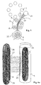
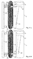
- Fig. 9, 10 , 11 , 12 and 13 a schematic drawing of deposition methods used for low arc spot speed target materials (for instance graphite) is presented.
- low arc spot speed target materials for instance graphite
- This system can work in various modes, which are presented in the above mentioned figures. Their description follows:
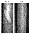
- Photograph illustrating arc spot movement on graphite target is shown in fig. 14 .
Landscapes
- Chemical & Material Sciences (AREA)
- Engineering & Computer Science (AREA)
- Organic Chemistry (AREA)
- Materials Engineering (AREA)
- Mechanical Engineering (AREA)
- Metallurgy (AREA)
- Chemical Kinetics & Catalysis (AREA)
- Physics & Mathematics (AREA)
- Plasma & Fusion (AREA)
- Analytical Chemistry (AREA)
- Health & Medical Sciences (AREA)
- Epidemiology (AREA)
- Public Health (AREA)
- Electromagnetism (AREA)
- Physical Vapour Deposition (AREA)
Claims (9)
- Appareil de dépôt sous vide par arc cathodique filtré pour l'application de revêtement sur des substrats sous vide comprenant :- une chambre de revêtement sous vide (2), un support de substrat (1) monté dans cette chambre de revêtement sous vide (2),- au moins une cathode de dépôt par arc cathodique consommable ayant essentiellement une forme cylindrique reliée au pole négatif d'une source de courant (12),- au moins une anode (10) associée à la cathode reliée au pole positif de la source de courant (12),- la cathode étant consommable par son enveloppe cylindrique externe,- au moins une bobine électromagnétique (8) refroidie par de l'eau pour créer un champ magnétique entre la cathode rotative et le support de substrat (1),
caractérisé en ce que
la cathode est une cathode rotative,
la bobine électromagnétique (8) refroidie par de l'eau a la forme d'un beignet allongé et la région centrale de plus forte intensité du champ magnétique de la bobine électromagnétique (8) refroidie par de l'eau est situé sur une droite qui est essentiellement parallèle à l'axe de la cathode rotative,- les lignes de champ magnétique (17) créées par la bobine électro-magnétique (8) refroidie par de l'eau sont essentiellement resserrées dans l'espace situé entre la cathode rotative et le support de substrat (1),- l'anode (10) est positionnée de sorte que la décharge d'arc s'enflamme de la cathode rotative au travers de la bobine électro-magnétique (8) refroidie par de l'eau vers l'anode (10). - Appareil de dépôt sous vide par arc cathodique filtré conforme à la revendication 1, dans lequel la face interne de la bobine électromagnétique (8) refroidie par de l'eau est équipée de déflecteurs (9) réfléchissant des macro particules.
- Appareil de dépôt sous vide par arc cathodique filtré conforme aux revendications 1 et 2, dans lequel la bobine électromagnétique (8) refroidie par de l'eau peut être déplacée le long de l'axe de rotation de la cathode rotative.
- Appareil de dépôt sous vide par arc cathodique filtré conforme aux revendications 1 et 2, dans lequel une source de champ magnétique additionnelle (6) orientée à l'opposé du champ magnétique est positionnée dans la cathode rotative.
- Appareil de dépôt sous vide par arc cathodique filtré conforme à la revendication 4, dans lequel au moins une partie de la source de champ magnétique additionnelle (6) est un noyau ferromagnétique (7) pouvant être déplacé le long de l'axe de rotation de la cathode rotative.
- Appareil de dépôt sous vide par arc cathodique filtré conforme aux revendications 1 à 5, dans lequel une anode additionnelle (24) est positionnée entre la cathode rotative et la bobine électromagnétique (8) refroidie par de l'eau, l'arc de courant créé par la source de courant (12) étant divisé entre l'anode additionnelle (24) et l'anode (10), le rapport entre l'arc de courant s'enflammant contre l'anode additionnelle (24) et l'arc de courant s'enflammant contre l'anode (10) étant situé dans la plage de 0,1 à 10.
- Procédé d'application de revêtements pour des matériaux-cibles à faible vitesse de spot d'arc, en particulier du graphite sur des substrats, dans un appareil de revêtement conforme à l'une quelconque des revendications 1 à 6, comprenant en outre :- deux détecteurs d'arc (19, 20) positionnés au niveau des emplacements occupés par le canal de plasma lorsque le spot d'arc atteint respectivement une première extrémité et une seconde extrémité, de la cathode rotative,- ce procédé comprenant des étapes consistant à :- créer un arc entre la cathode rotative au niveau d'une première position d'extrémité de la cathode rotative consommable et l'anode associée (10) pour créer le plasma à proximité de l'emplacement dans lequel les lignes de champ magnétique (17) sont essentiellement perpendiculaires (22) à la surface de la cathode rotative, c'est-à-dire de l'enveloppe cylindrique extérieure, où spot d'arc se déplace,- la rotation de la cathode (16) décalant le spot d'arc de l'emplacement dans lequel les lignes de champ magnétique (17) entrent dans la cathode rotative perpendiculairement à l'enveloppe cylindrique externe de la cathode vers l'emplacement de la composante de champ magnétique plus élevée qui est tangentielle à l'enveloppe cylindrique externe de la cathode rotative par rotation de la cible de façon à accélérer le déplacement du spot d'arc sur l'enveloppe cylindrique externe de la cathode rotative en direction de l'axe de rotation de la cathode rotative,- lorsque le spot d'arc atteint une seconde position d'extrémité de la cathode rotative consommable, l'une des actions ci-dessous est effectuée :- l'arc est éteint et réallumé,- la direction de déplacement du spot d'arc est inversée, la position de l'arc étant évaluée par le détecteur d'arc.
- Procédé conforme à la revendication 7, selon lequel la direction de déplacement du spot d'arc est inversée en modifiant le sens de rotation de la cathode rotative (16).
- Procédé conforme à la revendication 7, selon lequel la direction de déplacement du spot d'arc est inversée en modifiant l'orientation du courant (26) dans la bobine électromagnétique refroidie par de l'eau.
Priority Applications (1)
| Application Number | Priority Date | Filing Date | Title |
|---|---|---|---|
| EP12801511.2A EP2788522B1 (fr) | 2011-12-05 | 2012-11-30 | Appareil et procédé de dépôt sous vide par arc cathodique filtré et procédé |
Applications Claiming Priority (3)
| Application Number | Priority Date | Filing Date | Title |
|---|---|---|---|
| EP11191978.3A EP2602354A1 (fr) | 2011-12-05 | 2011-12-05 | Appareil et procédé de dépôt sous vide par arc cathodique filtré et procédé |
| EP12801511.2A EP2788522B1 (fr) | 2011-12-05 | 2012-11-30 | Appareil et procédé de dépôt sous vide par arc cathodique filtré et procédé |
| PCT/EP2012/074147 WO2013083495A1 (fr) | 2011-12-05 | 2012-11-30 | Appareil et procédé de dépôt par arc cathodique filtré |
Publications (2)
| Publication Number | Publication Date |
|---|---|
| EP2788522A1 EP2788522A1 (fr) | 2014-10-15 |
| EP2788522B1 true EP2788522B1 (fr) | 2016-02-03 |
Family
ID=47358135
Family Applications (2)
| Application Number | Title | Priority Date | Filing Date |
|---|---|---|---|
| EP11191978.3A Withdrawn EP2602354A1 (fr) | 2011-12-05 | 2011-12-05 | Appareil et procédé de dépôt sous vide par arc cathodique filtré et procédé |
| EP12801511.2A Not-in-force EP2788522B1 (fr) | 2011-12-05 | 2012-11-30 | Appareil et procédé de dépôt sous vide par arc cathodique filtré et procédé |
Family Applications Before (1)
| Application Number | Title | Priority Date | Filing Date |
|---|---|---|---|
| EP11191978.3A Withdrawn EP2602354A1 (fr) | 2011-12-05 | 2011-12-05 | Appareil et procédé de dépôt sous vide par arc cathodique filtré et procédé |
Country Status (6)
| Country | Link |
|---|---|
| US (1) | US9127354B2 (fr) |
| EP (2) | EP2602354A1 (fr) |
| JP (1) | JP6200899B2 (fr) |
| KR (1) | KR20140143352A (fr) |
| CN (1) | CN104364416B (fr) |
| WO (1) | WO2013083495A1 (fr) |
Families Citing this family (38)
| Publication number | Priority date | Publication date | Assignee | Title |
|---|---|---|---|---|
| WO2013170052A1 (fr) | 2012-05-09 | 2013-11-14 | Sio2 Medical Products, Inc. | Enrobage protecteur en saccharide pour conditionnement pharmaceutique |
| MX350703B (es) | 2009-05-13 | 2017-09-14 | Sio2 Medical Products Inc | Metodo de gasificacion para inspeccionar una superficie revestida. |
| US9458536B2 (en) | 2009-07-02 | 2016-10-04 | Sio2 Medical Products, Inc. | PECVD coating methods for capped syringes, cartridges and other articles |
| US11624115B2 (en) | 2010-05-12 | 2023-04-11 | Sio2 Medical Products, Inc. | Syringe with PECVD lubrication |
| US9878101B2 (en) | 2010-11-12 | 2018-01-30 | Sio2 Medical Products, Inc. | Cyclic olefin polymer vessels and vessel coating methods |
| US9272095B2 (en) | 2011-04-01 | 2016-03-01 | Sio2 Medical Products, Inc. | Vessels, contact surfaces, and coating and inspection apparatus and methods |
| US10304665B2 (en) | 2011-09-07 | 2019-05-28 | Nano-Product Engineering, LLC | Reactors for plasma-assisted processes and associated methods |
| US9761424B1 (en) | 2011-09-07 | 2017-09-12 | Nano-Product Engineering, LLC | Filtered cathodic arc method, apparatus and applications thereof |
| US11116695B2 (en) | 2011-11-11 | 2021-09-14 | Sio2 Medical Products, Inc. | Blood sample collection tube |
| EP2776603B1 (fr) | 2011-11-11 | 2019-03-06 | SiO2 Medical Products, Inc. | Revêtement de passivation, de protection de ph ou à pouvoir lubrifiant pour conditionnement pharmaceutique, processus et appareil de revêtement |
| US20150297800A1 (en) | 2012-07-03 | 2015-10-22 | Sio2 Medical Products, Inc. | SiOx BARRIER FOR PHARMACEUTICAL PACKAGE AND COATING PROCESS |
| GB201216138D0 (en) * | 2012-09-11 | 2012-10-24 | Gencoa Ltd | Plasma source |
| CA2890066C (fr) | 2012-11-01 | 2021-11-09 | Sio2 Medical Products, Inc. | Procedes d'inspection de revetement |
| US9903782B2 (en) | 2012-11-16 | 2018-02-27 | Sio2 Medical Products, Inc. | Method and apparatus for detecting rapid barrier coating integrity characteristics |
| JP6382830B2 (ja) | 2012-11-30 | 2018-08-29 | エスアイオーツー・メディカル・プロダクツ・インコーポレイテッド | 医療シリンジ、カートリッジ等上でのpecvd堆積の均一性制御 |
| US9764093B2 (en) | 2012-11-30 | 2017-09-19 | Sio2 Medical Products, Inc. | Controlling the uniformity of PECVD deposition |
| US9662450B2 (en) | 2013-03-01 | 2017-05-30 | Sio2 Medical Products, Inc. | Plasma or CVD pre-treatment for lubricated pharmaceutical package, coating process and apparatus |
| EP2971228B1 (fr) | 2013-03-11 | 2023-06-21 | Si02 Medical Products, Inc. | Emballage revêtu |
| US9937099B2 (en) | 2013-03-11 | 2018-04-10 | Sio2 Medical Products, Inc. | Trilayer coated pharmaceutical packaging with low oxygen transmission rate |
| US20160017490A1 (en) | 2013-03-15 | 2016-01-21 | Sio2 Medical Products, Inc. | Coating method |
| CN103643213B (zh) * | 2013-11-28 | 2016-03-30 | 中国科学院金属研究所 | 一种旋转横向磁场耦合轴向磁场辅助电弧离子镀装置 |
| WO2015148471A1 (fr) | 2014-03-28 | 2015-10-01 | Sio2 Medical Products, Inc. | Revêtements antistatiques pour des récipients en plastique |
| DE102015204592B4 (de) * | 2015-03-13 | 2016-12-08 | Fraunhofer-Gesellschaft zur Förderung der angewandten Forschung e.V. | Vorrichtung zum Beeinflussen einer Ausbreitung eines bei einem Vakuumlichtbogenprozess gebildeten Plasmas |
| CN104928625B (zh) | 2015-05-22 | 2017-06-16 | 沈阳富创精密设备有限公司 | 一种pvd制备半导体装备用抗高温蠕变接地基片的方法 |
| EP3337915B1 (fr) | 2015-08-18 | 2021-11-03 | SiO2 Medical Products, Inc. | Conditionnement pharmaceutique et autre présentant un faible taux de transmission d'oxygène |
| CZ306607B6 (cs) | 2016-02-05 | 2017-03-22 | Platit A.S. | Způsob nanášení otěruvzdorné DLC vrstvy |
| CN106947947A (zh) * | 2017-05-02 | 2017-07-14 | 上海理工大学 | 纳米喷涂设备 |
| WO2018236071A1 (fr) * | 2017-06-23 | 2018-12-27 | 주식회사 현대케피코 | Bille et siège de soupape pour injecteur de carburant et leur procédé de revêtement |
| KR102074771B1 (ko) * | 2017-06-23 | 2020-02-07 | 주식회사 현대케피코 | 연료 인젝터용 볼과 밸브 시트, 및 그 코팅 방법 |
| CN109989031A (zh) * | 2017-12-30 | 2019-07-09 | 魏永强 | 多级磁场和内衬异形管与多孔挡板复合型过滤的电弧离子镀 |
| US11834204B1 (en) | 2018-04-05 | 2023-12-05 | Nano-Product Engineering, LLC | Sources for plasma assisted electric propulsion |
| KR102188421B1 (ko) * | 2018-09-14 | 2020-12-08 | 주식회사 현대케피코 | 연료 인젝터용 볼과 밸브 시트, 및 그 코팅 방법 |
| KR102641947B1 (ko) * | 2018-11-13 | 2024-02-27 | 한국전기연구원 | 고장 전류 저감 장치 |
| CA3114863C (fr) * | 2018-11-19 | 2023-06-27 | Kvarc Services Inc | Appareil de revetement et son procede d'utilisation |
| SG11202109135UA (en) * | 2019-03-15 | 2021-09-29 | Nanofilm Tech International Limited | Improved cathode arc source |
| CN113278954A (zh) * | 2021-05-25 | 2021-08-20 | 南京邮电大学 | 一种复合涂层及其制备方法与应用和制备系统 |
| CN114086127B (zh) * | 2021-11-29 | 2023-10-27 | 青岛科技大学 | 一种磁场辅助阴极电弧离子镀蒸发源 |
| US12198905B2 (en) * | 2021-12-17 | 2025-01-14 | Vapor Technologies, Inc. | Multi racetrack cathodic arc |
Family Cites Families (26)
| Publication number | Priority date | Publication date | Assignee | Title |
|---|---|---|---|---|
| US4609564C2 (en) | 1981-02-24 | 2001-10-09 | Masco Vt Inc | Method of and apparatus for the coating of a substrate with material electrically transformed into a vapor phase |
| NL8700620A (nl) * | 1987-03-16 | 1988-10-17 | Hauzer Holding | Kathode boogverdampingsinrichting alsmede werkwijze voor het bedrijven daarvan. |
| US4859489A (en) | 1988-07-18 | 1989-08-22 | Vapor Technologies Inc. | Method of coating a metal gas-pressure bottle or tank |
| US5127030A (en) | 1989-02-28 | 1992-06-30 | American Science And Engineering, Inc. | Tomographic imaging with improved collimator |
| US5037522B1 (en) | 1990-07-24 | 1996-07-02 | Vergason Technology Inc | Electric arc vapor deposition device |
| US5126030A (en) | 1990-12-10 | 1992-06-30 | Kabushiki Kaisha Kobe Seiko Sho | Apparatus and method of cathodic arc deposition |
| US5269898A (en) * | 1991-03-20 | 1993-12-14 | Vapor Technologies, Inc. | Apparatus and method for coating a substrate using vacuum arc evaporation |
| US5194460A (en) | 1992-01-02 | 1993-03-16 | Dow Corning Corporation | Storage stable heat curable organosiloxane compositions containing a microencapsulated catalyst and method for preparing said catalyst |
| US5282944A (en) | 1992-07-30 | 1994-02-01 | The United States Of America As Represented By The United States Department Of Energy | Ion source based on the cathodic arc |
| US5435900A (en) | 1992-11-04 | 1995-07-25 | Gorokhovsky; Vladimir I. | Apparatus for application of coatings in vacuum |
| US5317235A (en) | 1993-03-22 | 1994-05-31 | Ism Technolog | Magnetically-filtered cathodic arc plasma apparatus |
| US5292944A (en) | 1993-06-29 | 1994-03-08 | E. I. Du Pont De Nemours And Company | Process for the preparation of adipic acid or pentenoic acid |
| US5468363A (en) * | 1994-04-25 | 1995-11-21 | Regents Of The University Of California | Magnetic-cusp, cathodic-arc source |
| CN1064294C (zh) | 1994-04-25 | 2001-04-11 | 吉莱特公司 | 制造剃刀刀片的方法 |
| US6103074A (en) | 1998-02-14 | 2000-08-15 | Phygen, Inc. | Cathode arc vapor deposition method and apparatus |
| DE19924094C2 (de) * | 1999-05-21 | 2003-04-30 | Fraunhofer Ges Forschung | Vakuumbogenverdampfer und Verfahren zu seinem Betrieb |
| JP2001059165A (ja) * | 1999-08-18 | 2001-03-06 | Nissin Electric Co Ltd | アーク式イオンプレーティング装置 |
| CA2305938C (fr) * | 2000-04-10 | 2007-07-03 | Vladimir I. Gorokhovsky | Methode et appareillage de depot d'arc cathodique filtre |
| US7033462B2 (en) * | 2001-11-30 | 2006-04-25 | Nissin Electric Co., Ltd. | Vacuum arc vapor deposition process and apparatus |
| JP4034563B2 (ja) * | 2001-12-27 | 2008-01-16 | 株式会社神戸製鋼所 | 真空アーク蒸発源 |
| US6756596B2 (en) | 2002-04-10 | 2004-06-29 | Paul E. Sathrum | Filtered ion source |
| JP4448004B2 (ja) * | 2004-10-20 | 2010-04-07 | 日新電機株式会社 | 物品処理装置 |
| DE102006009160B4 (de) * | 2006-02-22 | 2010-01-28 | Fraunhofer-Gesellschaft zur Förderung der angewandten Forschung e.V. | Anordnung für die Separation von Partikeln aus einem Plasma |
| US20090065350A1 (en) | 2007-09-07 | 2009-03-12 | Nanochip, Inc. | Filtered cathodic arc deposition with ion-species-selective bias |
| ES2774167T3 (es) * | 2008-09-02 | 2020-07-17 | Oerlikon Surface Solutions Ag Pfaeffikon | Dispositivo de revestimiento para el revestimiento de un sustrato, así como un procedimiento para el revestimiento de un sustrato |
| SG166695A1 (en) * | 2009-05-18 | 2010-12-29 | Cotec Pte Ltd | A coating apparatus |
-
2011
- 2011-12-05 EP EP11191978.3A patent/EP2602354A1/fr not_active Withdrawn
-
2012
- 2012-11-30 EP EP12801511.2A patent/EP2788522B1/fr not_active Not-in-force
- 2012-11-30 KR KR1020147015297A patent/KR20140143352A/ko not_active Ceased
- 2012-11-30 CN CN201280059992.4A patent/CN104364416B/zh not_active Expired - Fee Related
- 2012-11-30 US US14/362,301 patent/US9127354B2/en not_active Expired - Fee Related
- 2012-11-30 JP JP2014545191A patent/JP6200899B2/ja not_active Expired - Fee Related
- 2012-11-30 WO PCT/EP2012/074147 patent/WO2013083495A1/fr not_active Ceased
Also Published As
| Publication number | Publication date |
|---|---|
| US9127354B2 (en) | 2015-09-08 |
| US20140332370A1 (en) | 2014-11-13 |
| CN104364416A (zh) | 2015-02-18 |
| KR20140143352A (ko) | 2014-12-16 |
| JP2015503030A (ja) | 2015-01-29 |
| EP2788522A1 (fr) | 2014-10-15 |
| JP6200899B2 (ja) | 2017-09-20 |
| WO2013083495A1 (fr) | 2013-06-13 |
| CN104364416B (zh) | 2016-10-26 |
| EP2602354A1 (fr) | 2013-06-12 |
Similar Documents
| Publication | Publication Date | Title |
|---|---|---|
| EP2788522B1 (fr) | Appareil et procédé de dépôt sous vide par arc cathodique filtré et procédé | |
| EP0757615B1 (fr) | Procede de revetement de lames avec du diamant amorphe | |
| US5480527A (en) | Rectangular vacuum-arc plasma source | |
| RU2550502C2 (ru) | Модифицируемая конфигурация магнитов для электродуговых испарителей | |
| JP4689843B2 (ja) | 矩形陰極アーク源およびアークスポットの指向方法 | |
| KR20130121078A (ko) | 지정된 전기장을 갖는 아크 증착 소스 | |
| CN111748777B (zh) | 一种可变角度变径磁过滤阴极电弧薄膜沉积设备和方法 | |
| JP4989026B2 (ja) | 磁界発生装置付き真空アークソース | |
| US6756596B2 (en) | Filtered ion source | |
| US20130206585A1 (en) | Compact, filtered ion source | |
| JP7739250B2 (ja) | アーク蒸発源 | |
| AU712240B2 (en) | Amorphous diamond coating of blades | |
| CA2317234C (fr) | Revetement de lames avec du diamant amorphe | |
| MXPA96005104A (en) | Rectangular source of plasma de arco al va |
Legal Events
| Date | Code | Title | Description |
|---|---|---|---|
| PUAI | Public reference made under article 153(3) epc to a published international application that has entered the european phase |
Free format text: ORIGINAL CODE: 0009012 |
|
| 17P | Request for examination filed |
Effective date: 20140630 |
|
| AK | Designated contracting states |
Kind code of ref document: A1 Designated state(s): AL AT BE BG CH CY CZ DE DK EE ES FI FR GB GR HR HU IE IS IT LI LT LU LV MC MK MT NL NO PL PT RO RS SE SI SK SM TR |
|
| DAX | Request for extension of the european patent (deleted) | ||
| GRAP | Despatch of communication of intention to grant a patent |
Free format text: ORIGINAL CODE: EPIDOSNIGR1 |
|
| INTG | Intention to grant announced |
Effective date: 20150805 |
|
| GRAS | Grant fee paid |
Free format text: ORIGINAL CODE: EPIDOSNIGR3 |
|
| GRAA | (expected) grant |
Free format text: ORIGINAL CODE: 0009210 |
|
| AK | Designated contracting states |
Kind code of ref document: B1 Designated state(s): AL AT BE BG CH CY CZ DE DK EE ES FI FR GB GR HR HU IE IS IT LI LT LU LV MC MK MT NL NO PL PT RO RS SE SI SK SM TR |
|
| REG | Reference to a national code |
Ref country code: GB Ref legal event code: FG4D |
|
| REG | Reference to a national code |
Ref country code: AT Ref legal event code: REF Ref document number: 773752 Country of ref document: AT Kind code of ref document: T Effective date: 20160215 Ref country code: CH Ref legal event code: EP |
|
| REG | Reference to a national code |
Ref country code: IE Ref legal event code: FG4D |
|
| REG | Reference to a national code |
Ref country code: DE Ref legal event code: R096 Ref document number: 602012014532 Country of ref document: DE |
|
| REG | Reference to a national code |
Ref country code: SE Ref legal event code: TRGR |
|
| REG | Reference to a national code |
Ref country code: NL Ref legal event code: FP |
|
| REG | Reference to a national code |
Ref country code: LT Ref legal event code: MG4D |
|
| PG25 | Lapsed in a contracting state [announced via postgrant information from national office to epo] |
Ref country code: HR Free format text: LAPSE BECAUSE OF FAILURE TO SUBMIT A TRANSLATION OF THE DESCRIPTION OR TO PAY THE FEE WITHIN THE PRESCRIBED TIME-LIMIT Effective date: 20160203 Ref country code: NO Free format text: LAPSE BECAUSE OF FAILURE TO SUBMIT A TRANSLATION OF THE DESCRIPTION OR TO PAY THE FEE WITHIN THE PRESCRIBED TIME-LIMIT Effective date: 20160503 Ref country code: GR Free format text: LAPSE BECAUSE OF FAILURE TO SUBMIT A TRANSLATION OF THE DESCRIPTION OR TO PAY THE FEE WITHIN THE PRESCRIBED TIME-LIMIT Effective date: 20160504 Ref country code: FI Free format text: LAPSE BECAUSE OF FAILURE TO SUBMIT A TRANSLATION OF THE DESCRIPTION OR TO PAY THE FEE WITHIN THE PRESCRIBED TIME-LIMIT Effective date: 20160203 Ref country code: ES Free format text: LAPSE BECAUSE OF FAILURE TO SUBMIT A TRANSLATION OF THE DESCRIPTION OR TO PAY THE FEE WITHIN THE PRESCRIBED TIME-LIMIT Effective date: 20160203 |
|
| PG25 | Lapsed in a contracting state [announced via postgrant information from national office to epo] |
Ref country code: RS Free format text: LAPSE BECAUSE OF FAILURE TO SUBMIT A TRANSLATION OF THE DESCRIPTION OR TO PAY THE FEE WITHIN THE PRESCRIBED TIME-LIMIT Effective date: 20160203 Ref country code: IS Free format text: LAPSE BECAUSE OF FAILURE TO SUBMIT A TRANSLATION OF THE DESCRIPTION OR TO PAY THE FEE WITHIN THE PRESCRIBED TIME-LIMIT Effective date: 20160603 Ref country code: PT Free format text: LAPSE BECAUSE OF FAILURE TO SUBMIT A TRANSLATION OF THE DESCRIPTION OR TO PAY THE FEE WITHIN THE PRESCRIBED TIME-LIMIT Effective date: 20160603 Ref country code: PL Free format text: LAPSE BECAUSE OF FAILURE TO SUBMIT A TRANSLATION OF THE DESCRIPTION OR TO PAY THE FEE WITHIN THE PRESCRIBED TIME-LIMIT Effective date: 20160203 Ref country code: LT Free format text: LAPSE BECAUSE OF FAILURE TO SUBMIT A TRANSLATION OF THE DESCRIPTION OR TO PAY THE FEE WITHIN THE PRESCRIBED TIME-LIMIT Effective date: 20160203 Ref country code: LV Free format text: LAPSE BECAUSE OF FAILURE TO SUBMIT A TRANSLATION OF THE DESCRIPTION OR TO PAY THE FEE WITHIN THE PRESCRIBED TIME-LIMIT Effective date: 20160203 |
|
| REG | Reference to a national code |
Ref country code: CH Ref legal event code: PFA Owner name: PLATIT A.S., CZ Free format text: FORMER OWNER: PIVOT A.S., CZ Ref country code: CH Ref legal event code: NV Representative=s name: SCHMAUDER AND PARTNER AG PATENT- UND MARKENANW, CH |
|
| PG25 | Lapsed in a contracting state [announced via postgrant information from national office to epo] |
Ref country code: DK Free format text: LAPSE BECAUSE OF FAILURE TO SUBMIT A TRANSLATION OF THE DESCRIPTION OR TO PAY THE FEE WITHIN THE PRESCRIBED TIME-LIMIT Effective date: 20160203 Ref country code: EE Free format text: LAPSE BECAUSE OF FAILURE TO SUBMIT A TRANSLATION OF THE DESCRIPTION OR TO PAY THE FEE WITHIN THE PRESCRIBED TIME-LIMIT Effective date: 20160203 |
|
| REG | Reference to a national code |
Ref country code: DE Ref legal event code: R097 Ref document number: 602012014532 Country of ref document: DE |
|
| PG25 | Lapsed in a contracting state [announced via postgrant information from national office to epo] |
Ref country code: SM Free format text: LAPSE BECAUSE OF FAILURE TO SUBMIT A TRANSLATION OF THE DESCRIPTION OR TO PAY THE FEE WITHIN THE PRESCRIBED TIME-LIMIT Effective date: 20160203 Ref country code: SK Free format text: LAPSE BECAUSE OF FAILURE TO SUBMIT A TRANSLATION OF THE DESCRIPTION OR TO PAY THE FEE WITHIN THE PRESCRIBED TIME-LIMIT Effective date: 20160203 Ref country code: RO Free format text: LAPSE BECAUSE OF FAILURE TO SUBMIT A TRANSLATION OF THE DESCRIPTION OR TO PAY THE FEE WITHIN THE PRESCRIBED TIME-LIMIT Effective date: 20160203 |
|
| PLBE | No opposition filed within time limit |
Free format text: ORIGINAL CODE: 0009261 |
|
| STAA | Information on the status of an ep patent application or granted ep patent |
Free format text: STATUS: NO OPPOSITION FILED WITHIN TIME LIMIT |
|
| PG25 | Lapsed in a contracting state [announced via postgrant information from national office to epo] |
Ref country code: BE Free format text: LAPSE BECAUSE OF FAILURE TO SUBMIT A TRANSLATION OF THE DESCRIPTION OR TO PAY THE FEE WITHIN THE PRESCRIBED TIME-LIMIT Effective date: 20160203 |
|
| 26N | No opposition filed |
Effective date: 20161104 |
|
| PGFP | Annual fee paid to national office [announced via postgrant information from national office to epo] |
Ref country code: DE Payment date: 20161121 Year of fee payment: 5 Ref country code: LU Payment date: 20161121 Year of fee payment: 5 |
|
| PG25 | Lapsed in a contracting state [announced via postgrant information from national office to epo] |
Ref country code: BG Free format text: LAPSE BECAUSE OF FAILURE TO SUBMIT A TRANSLATION OF THE DESCRIPTION OR TO PAY THE FEE WITHIN THE PRESCRIBED TIME-LIMIT Effective date: 20160503 Ref country code: SI Free format text: LAPSE BECAUSE OF FAILURE TO SUBMIT A TRANSLATION OF THE DESCRIPTION OR TO PAY THE FEE WITHIN THE PRESCRIBED TIME-LIMIT Effective date: 20160203 |
|
| REG | Reference to a national code |
Ref country code: NL Ref legal event code: MM Effective date: 20161201 |
|
| GBPC | Gb: european patent ceased through non-payment of renewal fee |
Effective date: 20161130 |
|
| REG | Reference to a national code |
Ref country code: SE Ref legal event code: EUG |
|
| REG | Reference to a national code |
Ref country code: IE Ref legal event code: MM4A |
|
| REG | Reference to a national code |
Ref country code: FR Ref legal event code: ST Effective date: 20170731 |
|
| PG25 | Lapsed in a contracting state [announced via postgrant information from national office to epo] |
Ref country code: SE Free format text: LAPSE BECAUSE OF NON-PAYMENT OF DUE FEES Effective date: 20161201 |
|
| PG25 | Lapsed in a contracting state [announced via postgrant information from national office to epo] |
Ref country code: NL Free format text: LAPSE BECAUSE OF NON-PAYMENT OF DUE FEES Effective date: 20161201 |
|
| PG25 | Lapsed in a contracting state [announced via postgrant information from national office to epo] |
Ref country code: IT Free format text: LAPSE BECAUSE OF NON-PAYMENT OF DUE FEES Effective date: 20161130 Ref country code: FR Free format text: LAPSE BECAUSE OF NON-PAYMENT OF DUE FEES Effective date: 20161130 |
|
| PG25 | Lapsed in a contracting state [announced via postgrant information from national office to epo] |
Ref country code: GB Free format text: LAPSE BECAUSE OF NON-PAYMENT OF DUE FEES Effective date: 20161130 Ref country code: IE Free format text: LAPSE BECAUSE OF NON-PAYMENT OF DUE FEES Effective date: 20161130 |
|
| PGFP | Annual fee paid to national office [announced via postgrant information from national office to epo] |
Ref country code: CZ Payment date: 20171128 Year of fee payment: 6 |
|
| PGFP | Annual fee paid to national office [announced via postgrant information from national office to epo] |
Ref country code: CH Payment date: 20171018 Year of fee payment: 6 |
|
| PG25 | Lapsed in a contracting state [announced via postgrant information from national office to epo] |
Ref country code: HU Free format text: LAPSE BECAUSE OF FAILURE TO SUBMIT A TRANSLATION OF THE DESCRIPTION OR TO PAY THE FEE WITHIN THE PRESCRIBED TIME-LIMIT; INVALID AB INITIO Effective date: 20121130 |
|
| REG | Reference to a national code |
Ref country code: DE Ref legal event code: R119 Ref document number: 602012014532 Country of ref document: DE |
|
| PG25 | Lapsed in a contracting state [announced via postgrant information from national office to epo] |
Ref country code: MK Free format text: LAPSE BECAUSE OF FAILURE TO SUBMIT A TRANSLATION OF THE DESCRIPTION OR TO PAY THE FEE WITHIN THE PRESCRIBED TIME-LIMIT Effective date: 20160203 Ref country code: CY Free format text: LAPSE BECAUSE OF FAILURE TO SUBMIT A TRANSLATION OF THE DESCRIPTION OR TO PAY THE FEE WITHIN THE PRESCRIBED TIME-LIMIT Effective date: 20160203 Ref country code: MC Free format text: LAPSE BECAUSE OF FAILURE TO SUBMIT A TRANSLATION OF THE DESCRIPTION OR TO PAY THE FEE WITHIN THE PRESCRIBED TIME-LIMIT Effective date: 20160203 |
|
| PG25 | Lapsed in a contracting state [announced via postgrant information from national office to epo] |
Ref country code: LU Free format text: LAPSE BECAUSE OF NON-PAYMENT OF DUE FEES Effective date: 20171130 |
|
| PG25 | Lapsed in a contracting state [announced via postgrant information from national office to epo] |
Ref country code: MT Free format text: LAPSE BECAUSE OF NON-PAYMENT OF DUE FEES Effective date: 20161130 |
|
| PG25 | Lapsed in a contracting state [announced via postgrant information from national office to epo] |
Ref country code: TR Free format text: LAPSE BECAUSE OF FAILURE TO SUBMIT A TRANSLATION OF THE DESCRIPTION OR TO PAY THE FEE WITHIN THE PRESCRIBED TIME-LIMIT Effective date: 20160203 Ref country code: AL Free format text: LAPSE BECAUSE OF FAILURE TO SUBMIT A TRANSLATION OF THE DESCRIPTION OR TO PAY THE FEE WITHIN THE PRESCRIBED TIME-LIMIT Effective date: 20160203 Ref country code: DE Free format text: LAPSE BECAUSE OF NON-PAYMENT OF DUE FEES Effective date: 20180602 |
|
| REG | Reference to a national code |
Ref country code: AT Ref legal event code: MM01 Ref document number: 773752 Country of ref document: AT Kind code of ref document: T Effective date: 20171130 |
|
| PG25 | Lapsed in a contracting state [announced via postgrant information from national office to epo] |
Ref country code: AT Free format text: LAPSE BECAUSE OF NON-PAYMENT OF DUE FEES Effective date: 20171130 |
|
| REG | Reference to a national code |
Ref country code: CH Ref legal event code: PL |
|
| PG25 | Lapsed in a contracting state [announced via postgrant information from national office to epo] |
Ref country code: CZ Free format text: LAPSE BECAUSE OF NON-PAYMENT OF DUE FEES Effective date: 20181130 |
|
| PG25 | Lapsed in a contracting state [announced via postgrant information from national office to epo] |
Ref country code: LI Free format text: LAPSE BECAUSE OF NON-PAYMENT OF DUE FEES Effective date: 20181130 Ref country code: CH Free format text: LAPSE BECAUSE OF NON-PAYMENT OF DUE FEES Effective date: 20181130 |