EP2789286A1 - Tiroir à couverts pour lave-vaisselle - Google Patents
Tiroir à couverts pour lave-vaisselle Download PDFInfo
- Publication number
- EP2789286A1 EP2789286A1 EP20130001879 EP13001879A EP2789286A1 EP 2789286 A1 EP2789286 A1 EP 2789286A1 EP 20130001879 EP20130001879 EP 20130001879 EP 13001879 A EP13001879 A EP 13001879A EP 2789286 A1 EP2789286 A1 EP 2789286A1
- Authority
- EP
- European Patent Office
- Prior art keywords
- groove
- wing
- cutlery drawer
- drawer according
- cutlery
- Prior art date
- Legal status (The legal status is an assumption and is not a legal conclusion. Google has not performed a legal analysis and makes no representation as to the accuracy of the status listed.)
- Pending
Links
Images




Classifications
-
- A—HUMAN NECESSITIES
- A47—FURNITURE; DOMESTIC ARTICLES OR APPLIANCES; COFFEE MILLS; SPICE MILLS; SUCTION CLEANERS IN GENERAL
- A47L—DOMESTIC WASHING OR CLEANING; SUCTION CLEANERS IN GENERAL
- A47L15/00—Washing or rinsing machines for crockery or tableware
- A47L15/42—Details
- A47L15/50—Racks ; Baskets
- A47L15/502—Cutlery baskets
-
- A—HUMAN NECESSITIES
- A47—FURNITURE; DOMESTIC ARTICLES OR APPLIANCES; COFFEE MILLS; SPICE MILLS; SUCTION CLEANERS IN GENERAL
- A47L—DOMESTIC WASHING OR CLEANING; SUCTION CLEANERS IN GENERAL
- A47L15/00—Washing or rinsing machines for crockery or tableware
- A47L15/42—Details
- A47L15/50—Racks ; Baskets
- A47L15/503—Racks ; Baskets with foldable parts
Definitions
- the invention relates to a cutlery drawer for a dishwasher.
- a cutlery drawer Under a cutlery drawer is a basket-like receptacle in the broadest sense to understand, which is suitable for receiving cutlery, especially in a recumbent position, and which can be arranged to be pulled out in the dishwasher.
- the cutlery drawer may, at least in certain areas, also be suitable for receiving other small crockery, such as e.g. Espresso cups.
- a cutlery drawer for a dishwasher which comprises a frame in which a plurality of inserts are movably arranged.
- the two lateral inserts are arranged horizontally displaceable on the frame.
- a middle insert is provided, which is fastened by means of hangers on the frame, wherein the hangers are slidingly movable in the transverse direction.
- the hangers have guide pins which engage in guide grooves on the front and back plates of the middle part.
- the guide grooves have a slanted, elongated central region and two short, approximately horizontal end regions. This configuration of the guide grooves and their interaction with the guide pin is achieved that a horizontal displacement of the hanger of the center insert a vertical lifting or Lowering, ie a vertical displacement, causes the center insert.
- the inventive cutlery drawer comprises a receiving part for receiving dishes to be washed, in particular cutlery and small dishes such.
- the receiving part comprises a central part and a first lateral wing.
- the receiving part is provided with guide means, via which the first wing is connected to the central part in such a way that it can be displaced laterally or transversely and swiveled in its inclination relative to the central part.
- the first wing is from its horizontal starting position at least upwards, but preferably also pivoted downwards.
- a second side wing is provided, which is arranged on the central part opposite to the first side wing, wherein the second wing is connected via the guide means with the central part, that it is pivotable in its inclination relative to the central part and preferably also laterally or in Transverse direction is displaced. Also, the second wing is preferably pivoted from its horizontal starting position up and down.
- each link guide preferably has a first groove and a first sliding block, which is forcibly guided in the first groove.
- the first groove has a curved groove portion with at least two end points beyond which the first sliding block can not extend, the first of the end points being located above the second end point.
- the two end points form detent points / result in detent positions from which the first sliding block does not unintentionally, i. in particular not without force from the user, can slip out.
- the first groove is curved in the direction of the center of the middle part.
- the first groove preferably has an elongated portion extending inwardly toward the center of the central portion, which branches off the curved portion of the first groove between the first and second endpoints and has a third endpoint at its end forms, which also forms a resting point for the first sliding stone.
- the first groove on the central part and the sliding block are preferably arranged on the first wing.
- the first sliding block may be arranged on the middle part and the first groove on the first wing.
- the slotted guide for pivoting and optionally for lateral displacement of the second wing if provided, a second groove and a second sliding block, which are preferably designed and arranged as described for the first groove and the first sliding block (but mirror-inverted). Is not a lateral shift of the second Sash provided so can be dispensed with the inwardly extending elongated portion of the second groove. If, on the other hand, only a lateral displacement of the second wing is envisaged, the curved section can be dispensed with in the second groove.
- Both the first groove and the optionally provided second groove may be embodied as one or more groove elements, which are executed separately from the middle part, the first wing and the second wing, but are attached to the middle part or to the wings.
- the receiving volume can be flexibly adjusted by the first wing and possibly the second wing pivoted or moved in the transverse direction. If, for example, high dishes are to be placed in the dish rack, which is typically provided in a dishwasher below the cutlery drawer, then the first and / or the second wing of the cutlery drawer according to the invention can be folded up in order to make room for this. If this is not enough, the first and / or the second wing can be displaced inwards in the transverse direction, in order to create even more space for high dishes to be placed in the dish rack. However, if the crockery basket is loaded only with relatively low crockery, the first and / or the second wing can be folded down so that not only cutlery, but small crockery can be placed on the wings.
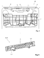
- the in FIG. 1 partly shown dishwasher 20 has a tub 1 for receiving dishes to be washed, also called ware on.
- a lower dish rack (not shown)
- an upper dish rack 2 and a first embodiment 3 of a cutlery drawer according to the invention are arranged in a conventional manner, wherein in the vertical direction of the upper crockery basket 2 above the lower crockery basket, not shown, and the cutlery drawer 3 above of the upper crockery basket 2 is arranged.
- the baskets and the cutlery drawer 3 are received in the tub 1 so that they can be at least partially pulled out of the tub 1 for loading and unloading.
- the baskets casters (not shown) may be provided, which are arranged on the side walls of the tub 1.
- the cutlery drawer 3 comprises a frame 4 and a receiving part 5 connected to the frame 4.
- the frame 4 consists, for example, of a bent metal rod and rests laterally on the rollers, not shown.
- the receiving part 5 is preferably designed in three parts and comprises a central part 6, a first wing 7 and a second wing 8, which are arranged laterally on the central part 6.
- the middle part 6 is fixed to the frame 4, and the wings 7, 8 are opposite to the central part 6 in a below with reference to the FIGS. 2 to 4 way described movably arranged.
- Both the central part 6 and the wings 7, 8 have a plurality of ribs, each forming a kind of basket in which small dishes can be accommodated.
- the ribs or the middle part 6 and the wings 7, 8 consist e.g. made of plastic and can be produced for example by injection molding.
- the bottom of the middle part 6 is in horizontal starting position of the wings 7, 8 preferably lower than the bottoms of the wings 7, 8, so that the middle part 6 and larger crockery, such.
- the wings 7, 8 are movable relative to the central part 6, so that the receiving part 5 can assume different configurations. This is in the FIGS. 2 to 4 illustrated.
- FIG. 2 also shows in FIG. 1 illustrated configuration of the receiving part 5 of the cutlery drawer 3.
- the wings 7, 8 are in their horizontal starting position and extend from the central part 6 laterally outwards, the bottoms of the wings 7, 8 extend horizontally.
- in the cutlery drawer 3 is relatively much space for receiving cutlery and the like.
- FIG. 3 shows a second configuration of the receiving part 5, in which the two wings 7, 8 are pivoted relative to the central part 6, that they projecting obliquely upward from the middle part 6, ie their bottoms rise away from the middle part 6 or towards the outside. They are inclined relative to the bottom of the middle part 6 obliquely upwards.
- the two wings 7, 8 are pivoted relative to the central part 6, that they projecting obliquely upward from the middle part 6, ie their bottoms rise away from the middle part 6 or towards the outside. They are inclined relative to the bottom of the middle part 6 obliquely upwards.
- larger spoons with the Laffe must be arranged inwardly in the wings 7, 8.
- FIG. 4 shows finally a third configuration in which one of the wings, in the present example, the first wing 7, is inserted in the horizontal direction in the middle part 6, while the second wing 8 as in in FIG. 3 shown second configuration obliquely upwardly and outwardly from the central portion 6 protrudes.
- the space in the cutlery drawer 3 and in its receiving part 5 is further reduced, but stands for more to be set in the upper crockery basket 2 dishes 21 even more space upwards.
- FIG. 5 illustrates which the cutlery drawer 3 and the receiving part 5 in the configuration according to FIG. 4 shows.
- FIG. 5 It will be seen that with the shown configuration of the cutlery drawer 3 in the upper crockery basket 2, relatively large items to be washed 21 can be adjusted, such as, for example, long-handled glasses.
- one or both wings 7, 8 can be pivoted downwards relative to the middle part 6 so that even on the wings 7, 8 small dishes can be parked.
- the inventive cutlery drawer 3 guide means 22 which are preferably designed as slide guide (s) (also known as slide mechanism).
- slide guide also known as slide mechanism.
- a slotted guide 22 is provided in each case. If, for the sake of simplicity, only embodiments for the front side or the front wall of the receiving part 5 or of the middle part 6 and the wings 6, 7 of the cutlery drawer 3 are made below, the same applies to those on the rear side (s) / rear wall or rear walls arranged slotted guide.
- the slotted guide 22 has a first groove 12.1 with a curved section 23.1 with two end points which lie substantially one over the other at different heights.
- a first sliding block 10.1 is forcibly guided.
- the first groove 12.1 is arranged on an inner side (or outer side) of a front wall of the middle part 6, specifically in a region near the first wing 7.
- the first groove 12.1 is preferably designed in the form of a separate groove element 24, as shown in FIG FIG. 6 is shown, and which on the inside (or outside) of the front wall of the middle part 6 is attached.
- the first sliding block 10.1 is in turn arranged on an outer side (or inner side) of a front wall of the first wing 7, specifically in the transverse direction substantially in the middle.
- the first sliding block 10.1 may also be arranged on the inside (or outside) of the front wall of the central part 6 and the first groove 12.1 also on the outside (or inside) of the front wall of the first wing 7.
- first sliding block 10.1 In the in FIG. 2 shown horizontal starting position of the first wing 7 is the first sliding block 10.1 at unspecified lower end point of the curved portion 23.1 of the first groove 12.1.
- first sliding block 10.1 is guided along the curved section 23.1 of the first groove 12.1 until it comes to lie in its upper end point, as shown in FIG FIG. 3 is shown.
- the first groove 12.1 furthermore has a section running inwardly in a transverse direction from the curved section 23.1, towards the middle of the middle part 6 or receiving part 5 extending elongated portion 25 with a third, unspecified end point.
- the elongate portion 25 is (slightly) bent up or lowered towards its end, so that the first sliding block 10.1 can not easily slide back from the third end point along the elongated portion 25 when it has come to rest in the third end point ,
- the first guide block 10.1 is guided first the curved section 23.1 and then the elongated section 25 up to its end point, as shown in FIG FIG. 4 is shown.
- the slotted guide 22 has a second groove 12.2 with a curved portion 23.2, for which the above with respect to the curved portion 23.1 of the first groove 12.1 applies, except that the curved portion 23.2 mirrored to the curved portion 23.1 is aligned. Furthermore, the slotted guide 22 has a second sliding block 10.2, which is forcibly guided in the second groove 12.2 or the curved section 23.2.
- the sliding block 10.2 is preferably arranged according to the sliding block 10.1 on an outer side (or inner side) of a front wall of the second wing 8, preferably centrally in the transverse direction, while the groove 12.2 is preferably arranged on an inner side (or outer side) of the front wall of the middle section 6 and Although preferred in a second wing 8 near range.
- the second groove 12.2 is preferably also executed separate groove element 24, as exemplified in FIG. 6 is shown.
- the second sliding block 10.2 can be arranged on the middle part 6 and the second groove 12.2 on the second wing 8, as described above for the first wing 7.
- the second wing 8 is pivoted upwards, in which the second sliding block 10.2 is moved upward from the lower end point of the second groove 12.2 in the curved section 23.2 and comes to lie in the upper end point of the second groove 12.2.
- the groove 12.2 can also have a substantially transversely inwardly extending elongated section, such as the elongate section 25 of the first groove 12.1, and reference is made to the above remarks on the elongated section 25 ,
- the slotted guide 22 preferably has a third groove 11 extending on an inner side (or outer side) of the front wall of the central part 6 in the transverse direction and in a third sliding block 9.1, on an outer side (or inner side) of the front wall of the first wing 7 is arranged, and a fourth sliding block 9.2, which is arranged on an outer side (or inner side) of the outer wall of the second wing 8, are positively guided.
- the third groove 11 preferably extends in an upper region of the front wall of the middle part 6.
- the sliding blocks 9.1 and 9.2 are preferably on middle-part-side end regions of the wings 7, 8 arranged.
- the third groove 11 is preferably formed as a separate groove element 24, as in FIG. 6 is shown.
- the third groove 11 and the sliding blocks 9.1, 9.2 serve to stabilize the movements of the wings 7, 8. If the wings 7, 8 are pivoted, then the sliding blocks 9.1, 9.2 remain in the end points of the third groove 11. If the wings 7, 8 but shifted inward, so the sliding blocks 9.1, 9.2 along the third groove 11 move inward.
- the wings 7, 8 can be adjusted in a simple manner and with only one hand.
- the wings 7, 8 may be provided with a handle, in particular laterally or on the respective front wall.
- grooves 12.1, 12.2, 11 are preferably for reinforcement wires or corresponding reinforcing elements introduced, in particular snapped.
- FIG. 6 shows, as indicated above, a groove element 24 of the slotted guide 22, which is applied as a separate part in each case on the rear wall and front wall of the middle part 6 of the cutlery drawer 3, in particular plugged, and advantageously can be prepared separately, for example by injection molding.
- the groove element 24 has the first groove 12.1 and spaced apart in the transverse direction, the second groove 12.2. Furthermore, the groove element 24 has the third groove 11 extending from the center on both sides in the transverse direction. Reference is made to the above description of the grooves 12.1, 12.2, 11.
- the separate production of the groove elements 24 and the middle part 6 makes it possible to achieve a better demolding of the injection-molded parts.
- FIG. 7 shows in particular the design of the bottoms of the wings 7, 8 and the middle part 6 with unspecified ribs.
- the ribs are, in the usual way, designed so that they form a support for cutlery or dishes, but not obstruct the flow of process water as possible.
- each holding rake 14a-14f has two elongated, mutually parallel supports 15a, 15b provided for mounting to the bottom of the cutlery drawer, interconnected by cross braces 16 and from which upwardly extending rods or needles 17 protrude Rods / needles 17 may be different.
- each holder rake 14a-14f may also comprise more than two carriers. Between adjacent bars or needles 17 can be successively (along the carrier 15 a, 15 b) introduced cutlery in a lateral position and held individually (see FIG. 13 ).
- Each of the racks 14a-14f may be positioned by the user in a variety of positions and orientations in the cutlery drawer 3, as shown in FIGS FIGS. 14 and 15 is illustrated, to which reference is made below.
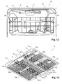
- FIGS. 8 to 13 essentially correspond to the FIGS. 1 to 7 However, they show a second embodiment 3 'of the inventive cutlery drawer.
- this embodiment 3 ' is now in the FIGS. 8 and 12 the storage of the frame 4 'is explicitly shown on rollers 28 provided on the side walls of the tub 1 of the dishwasher 20'.
- the cutlery drawer 3 ' according to the second embodiment has a receiving part 5' with a middle part 6 'and two wings 7, 8.
- the guide means 22 'instead of the third groove 11 of the first embodiment 3, which receives the sliding blocks 9.1, 9.2 of the first wing 7 and the second wing 8
- two grooves 11.1' and 11.2 '(third groove 11.1' and fourth groove 11.2 ') are provided, which extend substantially at the same height in the transverse direction and are preferably provided in an upper
- the groove 11.2 ' can be made substantially shorter than the groove 11.1'.
- a groove element corresponding to the in FIG. 6 for the first embodiment 3 shown groove member 24 corresponds, instead of the groove 11, the two grooves 11.1 'and 11.2' on.
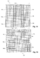
- FIGS. 14 and 15 show in the cutlery drawer 3, 3 'mounted holding rake 14a - 14f in different positions.
- the holding rakes 14a-14f are positioned in two rows, analogous to FIG FIG. 7 and FIG. 13
- the holding rakes 14a-14f are arranged in different positions.
- the holding ridges 14f, 14c, 14b, 14a are arranged at right angles to each other while the holding ridges 14f, 14e and 14d are arranged parallel to one another.
- one of the holding rakes 14a-14f can be inserted in the front area of the cutlery drawer 3, 3 'and serve to hold coffee spoons so that the user does not pull out the entire cutlery drawer 3, 3' in order to load the coffee spoons into the dishwasher 20, 20 ' but only the front area.
- FIGS. 14 and 15 illustrate further that the receiving part 5, 5 'of the cutlery drawer 3, 3' may consist only of a central part 6, 6 'and a wing 7, ie the dimensions of the central part 6, 6' in the transverse direction are in this case such that the middle part 6, 6 'replaces the second wing.
- a region 27 of the receiving part 5, 5 'of the cutlery drawer 3, 3' preferably has a higher static friction than the remaining regions of the receiving part 5, 5 '.
- the arranged in this region 27 ribs 26 have a higher static friction than the remaining, unspecified ribs of the receiving part 5, 5 ', by being preferably from non-slip or slip-resistant, (especially "softer") material such as silicone or coated with such a material at least on its upper side.
- the non-slip region 27 or the ribs 26 are provided in one or both wings 7, 8. This can advantageously be prevented that in this area 27 or on the ribs 26 stored cutlery, such as a knife with its handle, in the middle part 6, 6 'slips.
Landscapes
- Drawers Of Furniture (AREA)
Priority Applications (1)
| Application Number | Priority Date | Filing Date | Title |
|---|---|---|---|
| EP20130001879 EP2789286A1 (fr) | 2013-04-11 | 2013-04-11 | Tiroir à couverts pour lave-vaisselle |
Applications Claiming Priority (1)
| Application Number | Priority Date | Filing Date | Title |
|---|---|---|---|
| EP20130001879 EP2789286A1 (fr) | 2013-04-11 | 2013-04-11 | Tiroir à couverts pour lave-vaisselle |
Publications (1)
| Publication Number | Publication Date |
|---|---|
| EP2789286A1 true EP2789286A1 (fr) | 2014-10-15 |
Family
ID=48092667
Family Applications (1)
| Application Number | Title | Priority Date | Filing Date |
|---|---|---|---|
| EP20130001879 Pending EP2789286A1 (fr) | 2013-04-11 | 2013-04-11 | Tiroir à couverts pour lave-vaisselle |
Country Status (1)
| Country | Link |
|---|---|
| EP (1) | EP2789286A1 (fr) |
Cited By (6)
| Publication number | Priority date | Publication date | Assignee | Title |
|---|---|---|---|---|
| US20150245761A1 (en) * | 2012-09-26 | 2015-09-03 | Foshan Shunde Midea Washing Appliances Mfg. Co., Ltd. | Tray supporting apparatus for dishwasher, cutlery tray assembly and dishwasher |
| WO2017030355A1 (fr) | 2015-08-18 | 2017-02-23 | Lg Electronics Inc. | Panier et lave-vaisselle le comprenant |
| EP3175765A1 (fr) | 2015-12-02 | 2017-06-07 | Miele & Cie. KG | Panier à vaisselle, en particulier tiroir à couverts pour un lave-vaisselle |
| EP3175766A1 (fr) | 2015-12-02 | 2017-06-07 | Miele & Cie. KG | Tiroir à couverts pour un lave-vaisselle |
| WO2018082321A1 (fr) * | 2016-11-01 | 2018-05-11 | 佛山市顺德区美的洗涤电器制造有限公司 | Ensemble porte-couverts destiné à être utilisé dans un lave-vaisselle et lave-vaisselle équipé de celui-ci |
| EP3409182A1 (fr) | 2017-06-01 | 2018-12-05 | Miele & Cie. KG | Panier à vaisselle, notamment tiroir à couverts |
Citations (5)
| Publication number | Priority date | Publication date | Assignee | Title |
|---|---|---|---|---|
| EP1460929A1 (fr) * | 2001-12-28 | 2004-09-29 | BSH Bosch und Siemens Hausgeräte GmbH | Panier a couverts pour un lave-vaisselle |
| DE102006055352A1 (de) * | 2006-11-23 | 2008-05-29 | BSH Bosch und Siemens Hausgeräte GmbH | Besteckkorb für eine Geschirrspülmaschine und Geschirrspülmaschine |
| EP2433549A1 (fr) | 2008-12-18 | 2012-03-28 | Miele & Cie. KG | Tiroir à couverts pour un lave-vaisselle |
| DE102011081774A1 (de) * | 2011-08-30 | 2013-02-28 | BSH Bosch und Siemens Hausgeräte GmbH | Geschirrspülmaschine mit einer zur Halterung von kleinen Spülgutstücken, insbesondere Besteckteilen, vorgesehenen Aufnahmestruktur |
| EP2754377A1 (fr) | 2013-01-09 | 2014-07-16 | Miele & Cie. KG | Tiroir à couverts pour un lave-vaisselle |
-
2013
- 2013-04-11 EP EP20130001879 patent/EP2789286A1/fr active Pending
Patent Citations (5)
| Publication number | Priority date | Publication date | Assignee | Title |
|---|---|---|---|---|
| EP1460929A1 (fr) * | 2001-12-28 | 2004-09-29 | BSH Bosch und Siemens Hausgeräte GmbH | Panier a couverts pour un lave-vaisselle |
| DE102006055352A1 (de) * | 2006-11-23 | 2008-05-29 | BSH Bosch und Siemens Hausgeräte GmbH | Besteckkorb für eine Geschirrspülmaschine und Geschirrspülmaschine |
| EP2433549A1 (fr) | 2008-12-18 | 2012-03-28 | Miele & Cie. KG | Tiroir à couverts pour un lave-vaisselle |
| DE102011081774A1 (de) * | 2011-08-30 | 2013-02-28 | BSH Bosch und Siemens Hausgeräte GmbH | Geschirrspülmaschine mit einer zur Halterung von kleinen Spülgutstücken, insbesondere Besteckteilen, vorgesehenen Aufnahmestruktur |
| EP2754377A1 (fr) | 2013-01-09 | 2014-07-16 | Miele & Cie. KG | Tiroir à couverts pour un lave-vaisselle |
Cited By (12)
| Publication number | Priority date | Publication date | Assignee | Title |
|---|---|---|---|---|
| US20150245761A1 (en) * | 2012-09-26 | 2015-09-03 | Foshan Shunde Midea Washing Appliances Mfg. Co., Ltd. | Tray supporting apparatus for dishwasher, cutlery tray assembly and dishwasher |
| US9380926B2 (en) * | 2012-09-26 | 2016-07-05 | Foshan Shunde Midea Washing Appliances Mfg. Co., Ltd. | Tray supporting apparatus for dishwasher, cutlery tray assembly and dishwasher |
| WO2017030355A1 (fr) | 2015-08-18 | 2017-02-23 | Lg Electronics Inc. | Panier et lave-vaisselle le comprenant |
| AU2016307599B2 (en) * | 2015-08-18 | 2018-09-20 | Lg Electronics Inc. | Rack and dishwasher including the same |
| US10779705B2 (en) | 2015-08-18 | 2020-09-22 | Lg Electronics Inc. | Rack and dishwasher including the same |
| EP3175765A1 (fr) | 2015-12-02 | 2017-06-07 | Miele & Cie. KG | Panier à vaisselle, en particulier tiroir à couverts pour un lave-vaisselle |
| EP3175766A1 (fr) | 2015-12-02 | 2017-06-07 | Miele & Cie. KG | Tiroir à couverts pour un lave-vaisselle |
| DE102015120897A1 (de) | 2015-12-02 | 2017-06-08 | Miele & Cie. Kg | Besteckschublade für eine Geschirrspülmaschine |
| DE102015120890A1 (de) | 2015-12-02 | 2017-06-08 | Miele & Cie. Kg | Geschirrkorb, insbesondere Besteckschublade für eine Geschirrspülmaschine |
| WO2018082321A1 (fr) * | 2016-11-01 | 2018-05-11 | 佛山市顺德区美的洗涤电器制造有限公司 | Ensemble porte-couverts destiné à être utilisé dans un lave-vaisselle et lave-vaisselle équipé de celui-ci |
| EP3409182A1 (fr) | 2017-06-01 | 2018-12-05 | Miele & Cie. KG | Panier à vaisselle, notamment tiroir à couverts |
| EP3649912A1 (fr) | 2017-06-01 | 2020-05-13 | Miele & Cie. KG | Panier à vaisselle, notamment tiroir à couverts |
Similar Documents
| Publication | Publication Date | Title |
|---|---|---|
| EP2201887B1 (fr) | Tiroir à couverts pour un lave-vaisselle | |
| EP2754377B1 (fr) | Tiroir à couverts pour un lave-vaisselle | |
| EP2377455B1 (fr) | Panier de rinçage | |
| EP2789286A1 (fr) | Tiroir à couverts pour lave-vaisselle | |
| EP3649912B1 (fr) | Panier à vaisselle, notamment tiroir à couverts | |
| DE102014223373B3 (de) | Spülgutaufnahme und Haushaltsgeschirrspülmaschine | |
| DE102019216603B4 (de) | Etagere, Spülgutaufnahme und Haushaltsgeschirrspülmaschine | |
| DE102010042409B4 (de) | Geschirrspülmaschine mit einem ausziehbaren Rahmen und daran abstützbaren Einsätzen | |
| EP2777475A1 (fr) | Dispositif de support pour la coupe d'un verre destiné à être inséré dans un panier à vaisselle d'un lave-vaisselle | |
| DE102013103707A1 (de) | Besteckkorb | |
| DE20006243U1 (de) | Geschirrspüler mit herausnehmbaren Körben | |
| EP2896345B1 (fr) | Dispositif de réception pour un panier à vaisselle d'un appareil électroménager véhiculant de l'eau, panier à vaisselle d'un appareil électroménager véhiculant de l'eau et appareil électroménager véhiculant de l'eau. | |
| EP2865316A1 (fr) | Panier de lave-vaisselle | |
| DE102013211549B4 (de) | Geschirrspülmaschine | |
| DE102004035725A1 (de) | Geschirrspülmaschine mit variabler Vorrichtung zur Ablage von Spülgut | |
| EP3090677B1 (fr) | Tiroir à couverts pour lave-vaisselle | |
| DE29722001U1 (de) | Korb für Geschirrspülmaschine | |
| EP2250935B1 (fr) | Tiroir vertical pour armoire | |
| EP3175763A1 (fr) | Panier à vaisselle, notamment tiroir à couverts | |
| EP2250931B1 (fr) | Objet de dispositif d'armoire | |
| DE102014216388A1 (de) | Halteeinrichtung und Spülgutaufnahme | |
| DE102016209384B4 (de) | Nachrüstbare Hebevorrichtung und Geschirrspülmaschine | |
| WO2020038787A1 (fr) | Élément rapporté de support de verre | |
| EP2984980B1 (fr) | Porte-vaisselle d'un lave-vaissaille | |
| DE202018003163U1 (de) | Schrank, insbesondere Küchenschrank sowie Auszug für einen Schrank |
Legal Events
| Date | Code | Title | Description |
|---|---|---|---|
| PUAI | Public reference made under article 153(3) epc to a published international application that has entered the european phase |
Free format text: ORIGINAL CODE: 0009012 |
|
| 17P | Request for examination filed |
Effective date: 20130411 |
|
| AK | Designated contracting states |
Kind code of ref document: A1 Designated state(s): AL AT BE BG CH CY CZ DE DK EE ES FI FR GB GR HR HU IE IS IT LI LT LU LV MC MK MT NL NO PL PT RO RS SE SI SK SM TR |
|
| AX | Request for extension of the european patent |
Extension state: BA ME |
|
| TPAC | Observations filed by third parties |
Free format text: ORIGINAL CODE: EPIDOSNTIPA |
|
| R17P | Request for examination filed (corrected) |
Effective date: 20141201 |
|
| RBV | Designated contracting states (corrected) |
Designated state(s): AL AT BE BG CH CY CZ DE DK EE ES FI FR GB GR HR HU IE IS IT LI LT LU LV MC MK MT NL NO PL PT RO RS SE SI SK SM TR |
|
| 17Q | First examination report despatched |
Effective date: 20150217 |
|
| RAP1 | Party data changed (applicant data changed or rights of an application transferred) |
Owner name: V-ZUG AG |
|
| STAA | Information on the status of an ep patent application or granted ep patent |
Free format text: STATUS: EXAMINATION IS IN PROGRESS |
|
| GRAP | Despatch of communication of intention to grant a patent |
Free format text: ORIGINAL CODE: EPIDOSNIGR1 |
|
| STAA | Information on the status of an ep patent application or granted ep patent |
Free format text: STATUS: GRANT OF PATENT IS INTENDED |
|
| INTG | Intention to grant announced |
Effective date: 20251006 |
|
| GRAS | Grant fee paid |
Free format text: ORIGINAL CODE: EPIDOSNIGR3 |
|
| GRAJ | Information related to disapproval of communication of intention to grant by the applicant or resumption of examination proceedings by the epo deleted |
Free format text: ORIGINAL CODE: EPIDOSDIGR1 |
|
| GRAL | Information related to payment of fee for publishing/printing deleted |
Free format text: ORIGINAL CODE: EPIDOSDIGR3 |
|
| STAA | Information on the status of an ep patent application or granted ep patent |
Free format text: STATUS: EXAMINATION IS IN PROGRESS |
|
| GRAP | Despatch of communication of intention to grant a patent |
Free format text: ORIGINAL CODE: EPIDOSNIGR1 |
|
| STAA | Information on the status of an ep patent application or granted ep patent |
Free format text: STATUS: GRANT OF PATENT IS INTENDED |
|
| INTC | Intention to grant announced (deleted) | ||
| INTG | Intention to grant announced |
Effective date: 20260220 |
|
| GRAA | (expected) grant |
Free format text: ORIGINAL CODE: 0009210 |
|
| STAA | Information on the status of an ep patent application or granted ep patent |
Free format text: STATUS: THE PATENT HAS BEEN GRANTED |