EP2789413B1 - Régulation de température pour un dispositif de fabrication générative de composants et procédé de fabrication correspondant - Google Patents
Régulation de température pour un dispositif de fabrication générative de composants et procédé de fabrication correspondant Download PDFInfo
- Publication number
- EP2789413B1 EP2789413B1 EP13162645.9A EP13162645A EP2789413B1 EP 2789413 B1 EP2789413 B1 EP 2789413B1 EP 13162645 A EP13162645 A EP 13162645A EP 2789413 B1 EP2789413 B1 EP 2789413B1
- Authority
- EP
- European Patent Office
- Prior art keywords
- powder bed
- component
- induction coils
- powder
- induction coil
- Prior art date
- Legal status (The legal status is an assumption and is not a legal conclusion. Google has not performed a legal analysis and makes no representation as to the accuracy of the status listed.)
- Not-in-force
Links
Images

Classifications
-
- B—PERFORMING OPERATIONS; TRANSPORTING
- B23—MACHINE TOOLS; METAL-WORKING NOT OTHERWISE PROVIDED FOR
- B23K—SOLDERING OR UNSOLDERING; WELDING; CLADDING OR PLATING BY SOLDERING OR WELDING; CUTTING BY APPLYING HEAT LOCALLY, e.g. FLAME CUTTING; WORKING BY LASER BEAM
- B23K26/00—Working by laser beam, e.g. welding, cutting or boring
- B23K26/34—Laser welding for purposes other than joining
- B23K26/342—Build-up welding
-
- B—PERFORMING OPERATIONS; TRANSPORTING
- B22—CASTING; POWDER METALLURGY
- B22F—WORKING METALLIC POWDER; MANUFACTURE OF ARTICLES FROM METALLIC POWDER; MAKING METALLIC POWDER; APPARATUS OR DEVICES SPECIALLY ADAPTED FOR METALLIC POWDER
- B22F10/00—Additive manufacturing of workpieces or articles from metallic powder
- B22F10/20—Direct sintering or melting
- B22F10/28—Powder bed fusion, e.g. selective laser melting [SLM] or electron beam melting [EBM]
-
- B—PERFORMING OPERATIONS; TRANSPORTING
- B22—CASTING; POWDER METALLURGY
- B22F—WORKING METALLIC POWDER; MANUFACTURE OF ARTICLES FROM METALLIC POWDER; MAKING METALLIC POWDER; APPARATUS OR DEVICES SPECIALLY ADAPTED FOR METALLIC POWDER
- B22F10/00—Additive manufacturing of workpieces or articles from metallic powder
- B22F10/30—Process control
- B22F10/31—Calibration of process steps or apparatus settings, e.g. before or during manufacturing
-
- B—PERFORMING OPERATIONS; TRANSPORTING
- B22—CASTING; POWDER METALLURGY
- B22F—WORKING METALLIC POWDER; MANUFACTURE OF ARTICLES FROM METALLIC POWDER; MAKING METALLIC POWDER; APPARATUS OR DEVICES SPECIALLY ADAPTED FOR METALLIC POWDER
- B22F10/00—Additive manufacturing of workpieces or articles from metallic powder
- B22F10/30—Process control
- B22F10/36—Process control of energy beam parameters
- B22F10/362—Process control of energy beam parameters for preheating
-
- B—PERFORMING OPERATIONS; TRANSPORTING
- B22—CASTING; POWDER METALLURGY
- B22F—WORKING METALLIC POWDER; MANUFACTURE OF ARTICLES FROM METALLIC POWDER; MAKING METALLIC POWDER; APPARATUS OR DEVICES SPECIALLY ADAPTED FOR METALLIC POWDER
- B22F10/00—Additive manufacturing of workpieces or articles from metallic powder
- B22F10/30—Process control
- B22F10/36—Process control of energy beam parameters
- B22F10/364—Process control of energy beam parameters for post-heating, e.g. remelting
-
- B—PERFORMING OPERATIONS; TRANSPORTING
- B22—CASTING; POWDER METALLURGY
- B22F—WORKING METALLIC POWDER; MANUFACTURE OF ARTICLES FROM METALLIC POWDER; MAKING METALLIC POWDER; APPARATUS OR DEVICES SPECIALLY ADAPTED FOR METALLIC POWDER
- B22F12/00—Apparatus or devices specially adapted for additive manufacturing; Auxiliary means for additive manufacturing; Combinations of additive manufacturing apparatus or devices with other processing apparatus or devices
- B22F12/10—Auxiliary heating means
-
- B—PERFORMING OPERATIONS; TRANSPORTING
- B22—CASTING; POWDER METALLURGY
- B22F—WORKING METALLIC POWDER; MANUFACTURE OF ARTICLES FROM METALLIC POWDER; MAKING METALLIC POWDER; APPARATUS OR DEVICES SPECIALLY ADAPTED FOR METALLIC POWDER
- B22F12/00—Apparatus or devices specially adapted for additive manufacturing; Auxiliary means for additive manufacturing; Combinations of additive manufacturing apparatus or devices with other processing apparatus or devices
- B22F12/22—Driving means
- B22F12/224—Driving means for motion along a direction within the plane of a layer
-
- B—PERFORMING OPERATIONS; TRANSPORTING
- B22—CASTING; POWDER METALLURGY
- B22F—WORKING METALLIC POWDER; MANUFACTURE OF ARTICLES FROM METALLIC POWDER; MAKING METALLIC POWDER; APPARATUS OR DEVICES SPECIALLY ADAPTED FOR METALLIC POWDER
- B22F12/00—Apparatus or devices specially adapted for additive manufacturing; Auxiliary means for additive manufacturing; Combinations of additive manufacturing apparatus or devices with other processing apparatus or devices
- B22F12/90—Means for process control, e.g. cameras or sensors
-
- B—PERFORMING OPERATIONS; TRANSPORTING
- B23—MACHINE TOOLS; METAL-WORKING NOT OTHERWISE PROVIDED FOR
- B23K—SOLDERING OR UNSOLDERING; WELDING; CLADDING OR PLATING BY SOLDERING OR WELDING; CUTTING BY APPLYING HEAT LOCALLY, e.g. FLAME CUTTING; WORKING BY LASER BEAM
- B23K26/00—Working by laser beam, e.g. welding, cutting or boring
- B23K26/02—Positioning or observing the workpiece, e.g. with respect to the point of impact; Aligning, aiming or focusing the laser beam
- B23K26/03—Observing, e.g. monitoring, the workpiece
- B23K26/032—Observing, e.g. monitoring, the workpiece using optical means
-
- B—PERFORMING OPERATIONS; TRANSPORTING
- B23—MACHINE TOOLS; METAL-WORKING NOT OTHERWISE PROVIDED FOR
- B23K—SOLDERING OR UNSOLDERING; WELDING; CLADDING OR PLATING BY SOLDERING OR WELDING; CUTTING BY APPLYING HEAT LOCALLY, e.g. FLAME CUTTING; WORKING BY LASER BEAM
- B23K26/00—Working by laser beam, e.g. welding, cutting or boring
- B23K26/02—Positioning or observing the workpiece, e.g. with respect to the point of impact; Aligning, aiming or focusing the laser beam
- B23K26/03—Observing, e.g. monitoring, the workpiece
- B23K26/034—Observing the temperature of the workpiece
-
- B—PERFORMING OPERATIONS; TRANSPORTING
- B29—WORKING OF PLASTICS; WORKING OF SUBSTANCES IN A PLASTIC STATE IN GENERAL
- B29C—SHAPING OR JOINING OF PLASTICS; SHAPING OF MATERIAL IN A PLASTIC STATE, NOT OTHERWISE PROVIDED FOR; AFTER-TREATMENT OF THE SHAPED PRODUCTS, e.g. REPAIRING
- B29C64/00—Additive manufacturing, i.e. manufacturing of three-dimensional [3D] objects by additive deposition, additive agglomeration or additive layering, e.g. by 3D printing, stereolithography or selective laser sintering
- B29C64/10—Processes of additive manufacturing
- B29C64/141—Processes of additive manufacturing using only solid materials
- B29C64/153—Processes of additive manufacturing using only solid materials using layers of powder being selectively joined, e.g. by selective laser sintering or melting
-
- B—PERFORMING OPERATIONS; TRANSPORTING
- B33—ADDITIVE MANUFACTURING TECHNOLOGY
- B33Y—ADDITIVE MANUFACTURING, i.e. MANUFACTURING OF THREE-DIMENSIONAL [3D] OBJECTS BY ADDITIVE DEPOSITION, ADDITIVE AGGLOMERATION OR ADDITIVE LAYERING, e.g. BY 3D PRINTING, STEREOLITHOGRAPHY OR SELECTIVE LASER SINTERING
- B33Y30/00—Apparatus for additive manufacturing; Details thereof or accessories therefor
-
- B—PERFORMING OPERATIONS; TRANSPORTING
- B33—ADDITIVE MANUFACTURING TECHNOLOGY
- B33Y—ADDITIVE MANUFACTURING, i.e. MANUFACTURING OF THREE-DIMENSIONAL [3D] OBJECTS BY ADDITIVE DEPOSITION, ADDITIVE AGGLOMERATION OR ADDITIVE LAYERING, e.g. BY 3D PRINTING, STEREOLITHOGRAPHY OR SELECTIVE LASER SINTERING
- B33Y50/00—Data acquisition or data processing for additive manufacturing
- B33Y50/02—Data acquisition or data processing for additive manufacturing for controlling or regulating additive manufacturing processes
-
- H—ELECTRICITY
- H05—ELECTRIC TECHNIQUES NOT OTHERWISE PROVIDED FOR
- H05B—ELECTRIC HEATING; ELECTRIC LIGHT SOURCES NOT OTHERWISE PROVIDED FOR; CIRCUIT ARRANGEMENTS FOR ELECTRIC LIGHT SOURCES, IN GENERAL
- H05B6/00—Heating by electric, magnetic or electromagnetic fields
- H05B6/02—Induction heating
- H05B6/06—Control, e.g. of temperature, of power
-
- H—ELECTRICITY
- H05—ELECTRIC TECHNIQUES NOT OTHERWISE PROVIDED FOR
- H05B—ELECTRIC HEATING; ELECTRIC LIGHT SOURCES NOT OTHERWISE PROVIDED FOR; CIRCUIT ARRANGEMENTS FOR ELECTRIC LIGHT SOURCES, IN GENERAL
- H05B6/00—Heating by electric, magnetic or electromagnetic fields
- H05B6/02—Induction heating
- H05B6/10—Induction heating apparatus, other than furnaces, for specific applications
- H05B6/101—Induction heating apparatus, other than furnaces, for specific applications for local heating of metal pieces
-
- H—ELECTRICITY
- H05—ELECTRIC TECHNIQUES NOT OTHERWISE PROVIDED FOR
- H05B—ELECTRIC HEATING; ELECTRIC LIGHT SOURCES NOT OTHERWISE PROVIDED FOR; CIRCUIT ARRANGEMENTS FOR ELECTRIC LIGHT SOURCES, IN GENERAL
- H05B6/00—Heating by electric, magnetic or electromagnetic fields
- H05B6/02—Induction heating
- H05B6/36—Coil arrangements
- H05B6/40—Establishing desired heat distribution, e.g. to heat particular parts of workpieces
-
- H—ELECTRICITY
- H05—ELECTRIC TECHNIQUES NOT OTHERWISE PROVIDED FOR
- H05B—ELECTRIC HEATING; ELECTRIC LIGHT SOURCES NOT OTHERWISE PROVIDED FOR; CIRCUIT ARRANGEMENTS FOR ELECTRIC LIGHT SOURCES, IN GENERAL
- H05B6/00—Heating by electric, magnetic or electromagnetic fields
- H05B6/02—Induction heating
- H05B6/36—Coil arrangements
- H05B6/44—Coil arrangements having more than one coil or coil segment
-
- B—PERFORMING OPERATIONS; TRANSPORTING
- B22—CASTING; POWDER METALLURGY
- B22F—WORKING METALLIC POWDER; MANUFACTURE OF ARTICLES FROM METALLIC POWDER; MAKING METALLIC POWDER; APPARATUS OR DEVICES SPECIALLY ADAPTED FOR METALLIC POWDER
- B22F2999/00—Aspects linked to processes or compositions used in powder metallurgy
-
- B—PERFORMING OPERATIONS; TRANSPORTING
- B23—MACHINE TOOLS; METAL-WORKING NOT OTHERWISE PROVIDED FOR
- B23K—SOLDERING OR UNSOLDERING; WELDING; CLADDING OR PLATING BY SOLDERING OR WELDING; CUTTING BY APPLYING HEAT LOCALLY, e.g. FLAME CUTTING; WORKING BY LASER BEAM
- B23K2101/00—Articles made by soldering, welding or cutting
- B23K2101/001—Turbines
-
- Y—GENERAL TAGGING OF NEW TECHNOLOGICAL DEVELOPMENTS; GENERAL TAGGING OF CROSS-SECTIONAL TECHNOLOGIES SPANNING OVER SEVERAL SECTIONS OF THE IPC; TECHNICAL SUBJECTS COVERED BY FORMER USPC CROSS-REFERENCE ART COLLECTIONS [XRACs] AND DIGESTS
- Y02—TECHNOLOGIES OR APPLICATIONS FOR MITIGATION OR ADAPTATION AGAINST CLIMATE CHANGE
- Y02P—CLIMATE CHANGE MITIGATION TECHNOLOGIES IN THE PRODUCTION OR PROCESSING OF GOODS
- Y02P10/00—Technologies related to metal processing
- Y02P10/25—Process efficiency
Definitions
- the present invention relates to a method and a device for producing components by a generative manufacturing method, in particular a method by means of selective irradiation of a powder bed.
- the prior art discloses generative manufacturing processes for the rapid production of prototypes or for the production of components which are difficult to produce by other processes. Inter alia, methods such as selective laser melting (SLM), direct metal laser sintering (DMLS) or electron beam techniques are used. From the prior art, in particular also generative manufacturing processes for the production of components of a turbomachine, such as components of an aircraft engine or a gas turbine are known, for example, in the DE 10 2009 051 479 A1 described method or a corresponding device for producing a component of a turbomachine.
- SLM selective laser melting
- DMLS direct metal laser sintering
- electron beam techniques are used.
- generative manufacturing processes for the production of components of a turbomachine such as components of an aircraft engine or a gas turbine are known, for example, in the DE 10 2009 051 479 A1 described method or a corresponding device for producing a component of a turbomachine.
- a corresponding component is produced by layer-wise application of at least one powdered component material on a component platform in the region of a buildup and joining zone as well as layered and local melting or sintering of the component material by means of energy supplied in the region of the assembly and joining zone.
- the supply of energy takes place here via laser beams, such as CO 2 laser, Nd: YAG laser, Yb fiber laser and diode laser, or by electron beams.
- the produced component or the assembly and joining zone is further heated to a temperature just below the melting point of the component material by means of a zone furnace to maintain a directionally solidified or monocrystalline crystal structure.
- Inductive heating of the component to be produced in connection with the generative production of a component by means of selective laser melting is also known in the art EP 2 359 964 A1 described.
- the WO 2008/071165 A1 again describes an apparatus and a method for repairing turbine blades of gas turbines by means of powder build-up welding, wherein a radiation source, such as a laser or an electron beam, is used for the build-up welding. At the same time, a heating device for heating the blade to be repaired is provided via an induction coil.
- a radiation source such as a laser or an electron beam
- the present invention proposes to provide a local and individually adapted to the component geometry inductive heating to solve the above object and in particular for the prevention of cracks, which allows a defined temperature setting by a defined temperature monitoring and control of the operating parameters based on the temperature measurement defined way to make a necessary heating of the component.
- a device is proposed in which at least two induction coils can be moved or positioned relative to one or more powder bed spaces in which the powder bed is provided for the generative production of the component for the inductive heating of the generatively produced component.
- the relative mobility of the induction coils to the powder bed space can be done either by movement of the induction coils or by movement of the powder bed space.
- a temperature measuring device for measuring the temperature at at least one point of the powder bed and / or the component to be produced and a control device for controlling the operating parameters of the induction coil and / or the beam source is further provided, wherein the control device, the temperature measured by the temperature measuring device Control variable receives.
- the control device By providing the temperature measuring device and the control device, desired temperature ratios can be set since the control device alters the operating parameters of the induction coils and / or the beam source when the measured temperature deviates from the preset temperature.
- Operating parameters of the induction coils and / or the beam source are understood to be both the positioning of the induction coils and / or the beam of the radiation source, as well as other operating parameters, such as power consumption of the corresponding components and the like.
- the device is set up such that the temperature measurement takes place at least at a measuring point which is at least relative to a spatial direction relative to the position of the induction coils and / or the beam of the radiation source is fixed to set constant conditions with respect to the melting area.
- This can be in a defined way the set desired temperatures in the melting and in the range of the not yet melted powder or the already re-solidified melt and thus correspondingly locally defined temperature gradients that allow safe and damage-free solidification, including heavy-melt weldable alloys such as high temperature alloys.
- the highest possible processing speed can be achieved.
- a thermal imaging camera can be used, in which the temperature can be determined from the thermal image at defined points. So that a constant determination of the temperature with respect to the position of the induction coils and / or the beam of the beam source can be carried out, an evaluation unit of the thermal imaging camera can be transmitted the position of the induction coils and / or the beam of the beam source, so that the temperature measurement with respect to correct position can be determined to the induction coil and / or the beam of the beam source.
- an induction coil is understood as any device which can generate inductive heating, that is to say, for example, independently of the number of turns, so that the induction coil can also be referred to as an induction loop, for example.
- the present invention i. the arrangement of induction coils movable relative to one or more powder bedspaces can be used in various apparatuses for the generative production of components from a powder, such as the methods and devices for selective laser melting SLM described above and direct laser laser sintering DLS or the like electron beam method.
- the beam source of the device for the generative production of components can be any suitable beam source for this purpose.
- the device for the generative production of components may be designed such that the plurality of induction coils can be arranged in different positions relative to the powder bed or spaces. These can be defined positions at specific distances from one another or a stepless mobility and positionability of the induction coils can be realized.
- the induction coils can be arranged in any suitable position in which an inductive heating of the component to be produced generatively can be realized.
- each induction coil can be arranged above and / or laterally of the powder bed space (s).
- the induction coils can be displaceable in several offset planes, for example along a rail arrangement or along two mutually crossed rail arrangements, so that the induction coils in each case can be arranged in different positions, wherein the planes are parallel to a surface of the powder bed space in which the powder is connected by irradiation to a component.
- the component is formed in layers, can be selected by the appropriate positioning of the induction coils in a plane parallel to the surface in which the layer is applied, depending on the geometry of the component location, a suitable position of the induction coil ,
- the cross-section of the component in the construction direction can change significantly, for example, increase or decrease, so that can be followed by a movement of the induction coils of the component geometry and thus an accurate and accurate inductive heating of the component can be achieved.
- the induction coils so that they can be adjusted in a direction transverse to the surface of the powder bed space in which the powder is irradiated to a component, so that by varying the distance from the generating component with the induction coils, the heating can be controlled.
- induction coils Since several powder bed rooms can be arranged in a working space, can a plurality of induction coils are used, which are positionable with respect to different or a single powder bed space.
- the positioning of the induction coils can be independent of each other. Only possible collisions of induction coils with each other limit the individual mobility of an induction coil.
- two induction coils can be operated in a mutually crossed arrangement, wherein in particular in the crossing region of the beam of the beam source can be provided for melting the powder.
- the induction coils and / or the beam of the beam source can be independently controlled or regulated on the basis of the measurement results of one or more temperature measuring devices.
- a combined control which takes into account the modes of action of the other component in each case, is advantageous in order to enable optimal temperature adjustment by coordinated operation of induction coils and / or beam source.
- the fixation of a temperature measuring point to an induction coil and / or the beam of the beam source proposed for attaining defined temperature ratios can be realized for one or more measuring points per induction coil or beam and / or a temperature measuring point can with respect to several components, such as induction coils and beam of the beam source be fixed, the fixation can be done for example in relation to different spatial directions.
- a first temperature measuring point with respect to the X direction of a first induction coil, and simultaneously fixed with respect to the Y direction of a second induction coil while a second temperature measuring point with respect to the second induction coil and the Y direction of the first induction coil is fixed.
- a temperature measuring point can also be fixed with respect to a plurality of spatial directions, in particular independent spatial directions, to form an induction coil or the beam of the beam source.
- a plurality of temperature measuring points can be used, wherein, for example, one measuring point can detect the preheating of the powder, while another measuring point can detect and regulate the thermal after-treatment of the already solidified component.
- the position of one or more induction coils for inductive heating of the component can be individually determined by the described device according to the component geometry to be generated and / or a determined temperature and adjusted accordingly.
- the power of the induction coils can be suitably controlled and / or regulated, for example by adjusting the frequency with which the induction coils are operated.
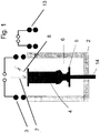
- the Fig. 1 shows a cross section through a powder bed space 2, in which, for example, a single turbine blade 4 is produced.
- the powder bed space 2 is essentially designed as a vessel in which a platform 5 is arranged movably via a punch 14. Powder is provided above the platform 5 in the powder bed space 2, which is initially arranged in the upper region of the powder bed space 2, so that there a laser beam 7 can melt the powder located on the platform 5, wherein after solidification of the melted powder a cross-sectional area of a corresponding component arises.
- the turbine blade 4 is produced step by step.
- the partially produced turbine blade 4 is inductively heated in the region of already molten and optionally already solidified material or kept at temperature or cooled slowly and controlled (reheating).
- two induction coils 3,13 are used, which are arranged above and / or laterally of the component or the turbine blade.
- the induction coils be used to preheat the powder, so that the laser beam 7 only has to cause a slight warming to the melting.
- a pyrometer or a thermal imaging camera For monitoring the preheating temperature and / or the Nachissermtemperatur a pyrometer or a thermal imaging camera is used, which detect the heat radiation 8 and can determine the temperature accordingly.
- the control or regulation of the induction coils 3,13 are made, with respect to the position in which the coils are arranged, and / or the power with the coils are operated.
- a corresponding control or regulation preferably be provided based on a data processing system with appropriate software.
- the positioning of the induction coils 3, 13 can be predetermined depending on the component geometry to be generated. Since the component geometry can change during the manufacturing process, the positions of the induction coils 3,13 can be changed accordingly.
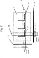
- FIG. 2 shows a plan view of a further embodiment of a device according to the invention, which is at least partially identical to the embodiment of Fig. 1 is or in which at least parts can be made identical.
- the embodiment of the Fig. 2 can be made in parallel in a working space 1 three components 4.
- the corresponding powder bed rooms are in the FIG. 2 not explicitly shown.
- the device according to FIG. 2 comprises two coils 3,13 which are linearly movable along the rail assemblies 11,12.
- the coils 3, 13 extend over the entire width or length of the working space 1 and thus can cover all areas for the production of components 4.
- the FIG. 2 shows purely schematically with the laser beam 7, which is directed from above onto the components to be produced 4, how the laser beam can be moved over the working space 1, to produce the components 4.
- the coils 3, 13 can be moved in accordance with the movement of the laser beam 7, in particular they can be moved out of the working range of the laser beam 7 at short notice.
- the coils 3, 13 can be moved along the rails 11, 12 in one plane or two mutually offset planes, which are aligned substantially parallel to the surface in which the powder is melted by the laser beam 7.
- the laser beam 7 can be provided in particular in the crossing region of the coils 3, 13, so that, on the one hand, the not yet melted powder can be preheated by the induction coils 3, 13 and the melt, which has already solidified to the component, can be subjected to a temperature aftertreatment.
- FIG. 3 shows a part of the FIG. 2 in greater detail, in particular the crossing region of the induction coils 3, 13 being shown.
- the laser beam 7 is arranged, which is moved along a meandering laser track 18 over the powder bed, in order to melt the powder. As soon as the laser beam 7 has moved further corresponding to the laser track 18, the melt solidifies again to form the component to be produced.
- the solidified region 16 is in the FIG. 3 shown in the left part of the figure. Accordingly, the loose powder disposed on the underlying already formed member 4 for forming the next layer is in the right part of FIG FIG. 3 is denoted by the reference numeral 17 for the powder area.
- the induction coils 3, 13 are each assigned a temperature measuring point 14, 15, wherein the first temperature measuring point 14 is arranged in the region 16 of the solidified melt, while the second temperature measuring point 15 is provided in the powder region 17. With the movement of the laser beam 7 along the laser path 18 across the work surface, the induction coils 3, 13 may also be moved to substantially maintain the arrangement with respect to the laser beam 7. However, it is not necessary to convert each movement of the laser beam 7 into a corresponding movement of the induction coils 3, 13, but it is sufficient, for example, if the laser beam 7 remains within the crossing region of the induction coils 3, 13. In the embodiment shown, this means that the laser beam 7 along the laser path 18 while oscillating in the picture of FIG.
- the induction coil 3 moved up and down, but does not leave the intersection of the induction coil 3,13 in this movement.
- the induction coil 3 can be kept stationary.
- the laser beam 7 moves along the laser path 18 in the image of FIG. 3 from left to right, so that the induction coil 13 is also moved to the right with increasing movement of the laser beam 7 to the right.
- the temperature measuring points 14,15 corresponding to the movement of the induction coil 13 will perform a movement to the right, while in a vertical direction thereto, ie in the image of the FIG. 3 up or down the temperature measuring points 14,15 remain stationary to the induction coil 3.
- the two temperature measuring points 14,15 are each fixed in one direction with respect to each coil 3,13.
- the temperature measuring points 14,15 are fixed with respect to the induction coil 13, while in a direction perpendicular thereto, ie in a direction in the FIG. 3 from top to bottom or vice versa, the temperature measuring points 14,15 are fixed relative to the induction coil 3.
Landscapes
- Engineering & Computer Science (AREA)
- Physics & Mathematics (AREA)
- Chemical & Material Sciences (AREA)
- Materials Engineering (AREA)
- Manufacturing & Machinery (AREA)
- Optics & Photonics (AREA)
- Mechanical Engineering (AREA)
- Plasma & Fusion (AREA)
- Automation & Control Theory (AREA)
- Electromagnetism (AREA)
- Analytical Chemistry (AREA)
- Powder Metallurgy (AREA)
Claims (13)
- Dispositif de fabrication de manière générative de composants (4) au moyen d'une irradiation sélective d'un lit de poudre (6), où le dispositif présente un espace de travail (1) dans lequel sont disposés au moins un espace de lit de poudre (2) et au moins une source de rayonnement, de sorte que la source de rayonnement peut irradier une poudre dans l'espace de lit de poudre (2) et le dispositif comprenant plusieurs bobines d'induction (3, 13) de sorte que le lit de poudre et/ou un composant qui est créé par l'irradiation (7) du lit de poudre peut être au moins partiellement réchauffé par induction,
caractérisé en ce- qu'au moins deux bobines d'induction (3, 13) peuvent être déplacées indépendamment l'une de l'autre par rapport à l'espace ou aux espaces de lit de poudre (2) et peuvent être déplacées dans un ou plusieurs plans qui sont parallèles par rapport à une surface de l'espace de lit de poudre (2), dans lesquels la poudre est assemblée pour constituer un composant (4) par irradiation,
où la première bobine d'induction peut être déplacée le long d'une première direction spatiale et une deuxième bobine d'induction peut être déplacée dans une deuxième direction spatiale qui est indépendante de la première direction spatiale, et- le dispositif comprend en outre un dispositif de mesure de la température pour la mesure de la température au niveau d'au moins un point du lit de poudre et/ou du composant à fabriquer, et un dispositif de régulation pour la régulation des paramètres de fonctionnement des bobines d'induction et/ou de la source de rayonnement, où- le dispositif de régulation reçoit la température mesurée par le dispositif de mesure de la température sous la forme d'une grandeur de réglage, et- le dispositif de mesure de la température est conçu de telle manière que l'au moins un point de mesure est fixé au moins en ce qui concerne une direction spatiale par rapport à la position de la bobine d'induction et/ou au faisceau de la source de rayonnement. - Dispositif selon la revendication 1,
caractérisé en ce que
le dispositif de mesure de la température comprend une caméra thermique. - Dispositif selon la revendication 1 ou 2,
caractérisé en ce que
les bobines d'induction (3, 13) peuvent être disposées au-dessus et/ou à côté de l'espace ou des espaces de lit de poudre (2) dans différentes positions. - Dispositif selon l'une des revendications précédentes,
caractérisé en ce que
les bobines d'induction (3, 13) peuvent être disposées dans un plan à différentes positions, le plan étant parallèle à une surface de l'espace de lit de poudre (2) dans laquelle la poudre est assemblée pour constituer le composant (4) par l'irradiation. - Dispositif selon l'une des revendications précédentes,
caractérisé en ce que
les bobines d'induction (3, 13) peuvent être réglées au niveau de leur position dans une direction perpendiculaire à une surface de l'espace de lit de poudre (2), dans laquelle la poudre (6) est assemblée pour constituer le composant (4) par l'irradiation. - Dispositif selon l'une des revendications précédentes,
caractérisé en ce que
les bobines d'induction (3, 13) peuvent être disposées sous forme croisée par rapport au cas d'un seul espace de lit de poudre (2). - Dispositif selon l'une des revendications précédentes,
caractérisé en ce que
chaque bobine d'induction, et/ou chaque source de rayonnement, peuvent être commandées indépendamment l'une de l'autre par le dispositif de régulation. - Dispositif selon l'une des revendications précédentes,
caractérisé en ce
qu'au moins un point de mesure est associé à chaque bobine d'induction et/ou un point de mesure est associé à plusieurs bobines d'induction. - Procédé de fabrication de manière générative de composants (4) avec un dispositif selon l'une des revendications précédentes, lequel comprend une irradiation sélective d'un lit de poudre (6) avec une source de rayonnement, où le composant (4) fabriqué et/ou le lit de poudre (6) sont chauffés simultanément par induction,
caractérisé en ce- qu'en partant de la géométrie du composant à fabriquer, la position de plusieurs bobines d'induction (3, 13) est déterminée et réglée pour le chauffage par induction, et- qu'au moins deux bobines d'induction sont déplacées dans un ou plusieurs plans qui sont parallèles à une surface du lit de poudre dans laquelle la poudre est assemblée pour constituer un composant (4) par l'irradiation,
où la première bobine d'induction peut être déplacée le long d'une première direction spatiale et une deuxième bobine d'induction peut être déplacée dans une deuxième direction spatiale, qui est indépendante de la première direction spatiale,- et qu'au moins au niveau d'un point qui est fixé au moins en ce qui concerne une direction spatiale par rapport aux bobines d'induction et/ou au faisceau de la source de rayonnement, la température du lit de poudre et/ou du composant fabriqué est mesurée avec laquelle les paramètres de fonctionnement de la bobine d'induction et/ou de la source de rayonnement sont commandés. - Procédé selon la revendication 9,
caractérisé en ce que
la position des bobines d'induction est réglée en fonction de la position du faisceau de la source de rayonnement et/ou de la température mesurée. - Procédé selon la revendication 9 ou 10,
caractérisé en ce que
la première et la deuxième bobine d'induction sont disposées croisées l'une par rapport à l'autre et que le faisceau de la source de rayonnement est disposé dans la zone du croisement. - Procédé selon l'une des revendications 9 à 11,
caractérisé en ce
qu'une bobine d'induction est employée pour le préchauffage du composant et une autre bobine d'induction est employée pour le chauffage ultérieur du composant fabriqué. - Procédé selon l'une des revendications 9 à 12,
caractérisé en ce que,
pour chaque bobine d'induction, la température est déterminée au niveau d'au moins un point de mesure associé à la bobine d'induction.
Priority Applications (3)
| Application Number | Priority Date | Filing Date | Title |
|---|---|---|---|
| EP13162645.9A EP2789413B1 (fr) | 2013-04-08 | 2013-04-08 | Régulation de température pour un dispositif de fabrication générative de composants et procédé de fabrication correspondant |
| US14/782,486 US10464170B2 (en) | 2013-04-08 | 2014-02-27 | Temperature regulation for a device for the additive manufacturing of components and corresponding production method |
| PCT/EP2014/000512 WO2014166567A1 (fr) | 2013-04-08 | 2014-02-27 | Régulation de température pour un dispositif servant à fabriquer de manière générative des composants et procédé de fabrication associé |
Applications Claiming Priority (1)
| Application Number | Priority Date | Filing Date | Title |
|---|---|---|---|
| EP13162645.9A EP2789413B1 (fr) | 2013-04-08 | 2013-04-08 | Régulation de température pour un dispositif de fabrication générative de composants et procédé de fabrication correspondant |
Publications (2)
| Publication Number | Publication Date |
|---|---|
| EP2789413A1 EP2789413A1 (fr) | 2014-10-15 |
| EP2789413B1 true EP2789413B1 (fr) | 2019-01-16 |
Family
ID=48092722
Family Applications (1)
| Application Number | Title | Priority Date | Filing Date |
|---|---|---|---|
| EP13162645.9A Not-in-force EP2789413B1 (fr) | 2013-04-08 | 2013-04-08 | Régulation de température pour un dispositif de fabrication générative de composants et procédé de fabrication correspondant |
Country Status (3)
| Country | Link |
|---|---|
| US (1) | US10464170B2 (fr) |
| EP (1) | EP2789413B1 (fr) |
| WO (1) | WO2014166567A1 (fr) |
Families Citing this family (54)
| Publication number | Priority date | Publication date | Assignee | Title |
|---|---|---|---|---|
| DE102013212620A1 (de) * | 2013-06-28 | 2014-12-31 | Trumpf Gmbh + Co. Kg | Verfahren und Bearbeitungsmaschine zum Generieren eines dreidimensionalen Bauteils durch selektives Laserschmelzen |
| CN105705278B (zh) * | 2013-11-14 | 2018-06-22 | 通用电气公司 | 单晶合金构件的分层制造 |
| DE102014203711A1 (de) * | 2014-02-28 | 2015-09-03 | MTU Aero Engines AG | Erzeugung von Druckeigenspannungen bei generativer Fertigung |
| GB2546016B (en) | 2014-06-20 | 2018-11-28 | Velo3D Inc | Apparatuses, systems and methods for three-dimensional printing |
| DE102015103127A1 (de) * | 2015-03-04 | 2016-09-08 | Trumpf Laser- Und Systemtechnik Gmbh | Bestrahlungssystem für eine Vorrichtung zur generativen Fertigung |
| DE102015214994A1 (de) * | 2015-08-06 | 2017-02-09 | MTU Aero Engines AG | Ein Verfahren zur Herstellung oder Reparatur eines Bauteils und Vorrichtung zur Herstellung und Reparatur eines Bauteils |
| US10443115B2 (en) * | 2015-08-20 | 2019-10-15 | General Electric Company | Apparatus and method for direct writing of single crystal super alloys and metals |
| US10343392B2 (en) * | 2015-08-27 | 2019-07-09 | General Electric Company | Powder-bed additive manufacturing devices and methods |
| EP3147048B1 (fr) * | 2015-09-28 | 2020-08-05 | Ecole Polytechnique Federale De Lausanne (Epfl) | Procédé et dispositif d'application d'un martelage par choc laser (lsp) ou d'un martelage à chaud par choc laser (wlsp) lors de la fusion sélective par laser (slm) |
| CN105252001B (zh) * | 2015-11-03 | 2017-08-15 | 中国航空工业集团公司北京航空材料研究院 | 一种钛合金整体叶盘叶片的激光成形制造工艺 |
| JP2018535121A (ja) | 2015-11-06 | 2018-11-29 | ヴェロ・スリー・ディー・インコーポレイテッド | 熟達した3次元印刷 |
| US10207454B2 (en) | 2015-12-10 | 2019-02-19 | Velo3D, Inc. | Systems for three-dimensional printing |
| US20170239891A1 (en) | 2016-02-18 | 2017-08-24 | Velo3D, Inc. | Accurate three-dimensional printing |
| US10981333B2 (en) * | 2016-04-26 | 2021-04-20 | Hewlett-Packard Development Company, L.P. | Additive manufacturing apparatus and method with fusing agent presence determined by temperature measurement |
| DE102016211321A1 (de) * | 2016-06-24 | 2017-12-28 | MTU Aero Engines AG | Induktionsheizvorrichtung, Vorrichtung mit mindestens einer Induktionsheizvorrichtung und Verfahren zur induktiven Erwärmung von Bauelementen oder eines Bauteilwerkstoffs |
| US11691343B2 (en) | 2016-06-29 | 2023-07-04 | Velo3D, Inc. | Three-dimensional printing and three-dimensional printers |
| WO2018005439A1 (fr) | 2016-06-29 | 2018-01-04 | Velo3D, Inc. | Impression 3d et imprimantes 3d |
| DE102016214170A1 (de) * | 2016-08-01 | 2018-02-01 | MTU Aero Engines AG | Induktionsheizvorrichtung, Vorrichtung mit mindestens einer Induktionsheizvorrichtung und Verfahren zur induktiven Erwärmung von Bauelementen oder eines Bauteilwerkstoffs |
| US20180095450A1 (en) | 2016-09-30 | 2018-04-05 | Velo3D, Inc. | Three-dimensional objects and their formation |
| US10661341B2 (en) | 2016-11-07 | 2020-05-26 | Velo3D, Inc. | Gas flow in three-dimensional printing |
| DE102016223215A1 (de) * | 2016-11-23 | 2018-05-24 | Trumpf Laser- Und Systemtechnik Gmbh | Bestrahlungseinrichtung und Bearbeitungsmaschine damit |
| US20180186080A1 (en) | 2017-01-05 | 2018-07-05 | Velo3D, Inc. | Optics in three-dimensional printing |
| US11072123B2 (en) | 2017-01-18 | 2021-07-27 | Hewlett-Packard Development Company, L.P. | Deviant control in additive manufacturing |
| WO2018160807A1 (fr) | 2017-03-02 | 2018-09-07 | Velo3D, Inc. | Impression tridimensionnelle d'objets tridimensionnels |
| DE102017104506A1 (de) | 2017-03-03 | 2018-09-06 | Cl Schutzrechtsverwaltungs Gmbh | Vorrichtung zur additiven Herstellung dreidimensionaler Objekte |
| US10449696B2 (en) | 2017-03-28 | 2019-10-22 | Velo3D, Inc. | Material manipulation in three-dimensional printing |
| WO2018209226A1 (fr) * | 2017-05-11 | 2018-11-15 | Seurat Technologies, Inc. | Guidage à semi-conducteurs de lumière à motifs pour optimisation de fabrication additive |
| DE102017208092A1 (de) * | 2017-05-15 | 2018-11-15 | MTU Aero Engines AG | Schichtbauverfahren und Schichtbauvorrichtung zum additiven Herstellen zumindest eines Bauteilbereichs eines Bauteils |
| DE102017216411A1 (de) * | 2017-09-15 | 2019-03-21 | MTU Aero Engines AG | Verfahren zur generativen Herstellung von Bauteilen sowie Vorrichtung zur Durchführung des Verfahrens |
| US10933493B2 (en) | 2017-09-25 | 2021-03-02 | Raytheon Technologies Corporation | Additive manufacturing in situ stress relief |
| EP3498401A1 (fr) * | 2017-12-18 | 2019-06-19 | Siemens Aktiengesellschaft | Procédé de fabrication additive d'un composant, appareil et produit-programme d'ordinateur |
| DE102017130282A1 (de) * | 2017-12-18 | 2019-06-19 | MTU Aero Engines AG | Verfahren und Vorrichtung zum additiven Herstellen eines Bauteil sowie Bauteil |
| US10272525B1 (en) | 2017-12-27 | 2019-04-30 | Velo3D, Inc. | Three-dimensional printing systems and methods of their use |
| US10144176B1 (en) | 2018-01-15 | 2018-12-04 | Velo3D, Inc. | Three-dimensional printing systems and methods of their use |
| DE102018203273A1 (de) | 2018-03-06 | 2019-09-12 | MTU Aero Engines AG | Induktionsheizvorrichtung, Vorrichtung zur additiven Herstellung zumindest eines Bauteilbereichs eines Bauteils mit einer solchen Induktionsheizvorrichtung, Verfahren zum induktiven Erwärmen eines Bauteilbereichs und Bauteil für eine Strömungsmaschine |
| EP3575017A1 (fr) * | 2018-05-30 | 2019-12-04 | Siemens Aktiengesellschaft | Procédure et configuration de fabrication additive |
| US11426818B2 (en) | 2018-08-10 | 2022-08-30 | The Research Foundation for the State University | Additive manufacturing processes and additively manufactured products |
| EP3656489A1 (fr) * | 2018-11-22 | 2020-05-27 | Siemens Aktiengesellschaft | Procédé de régulation pour la fabrication additive |
| US11344979B2 (en) | 2019-01-30 | 2022-05-31 | General Electric Company | Build plate clamping-assembly and additive manufacturing systems and methods of additively printing on workpieces |
| US11407035B2 (en) | 2019-01-30 | 2022-08-09 | General Electric Company | Powder seal assembly for decreasing powder usage in a powder bed additive manufacturing process |
| US11426799B2 (en) | 2019-01-30 | 2022-08-30 | General Electric Company | Powder seal assembly for decreasing powder usage in a powder bed additive manufacturing process |
| US11465245B2 (en) | 2019-01-30 | 2022-10-11 | General Electric Company | Tooling assembly for magnetically aligning components in an additive manufacturing machine |
| US11173574B2 (en) | 2019-01-30 | 2021-11-16 | General Electric Company | Workpiece-assembly and additive manufacturing systems and methods of additively printing on workpieces |
| US11458681B2 (en) | 2019-01-30 | 2022-10-04 | General Electric Company | Recoating assembly for an additive manufacturing machine |
| US11144034B2 (en) | 2019-01-30 | 2021-10-12 | General Electric Company | Additive manufacturing systems and methods of generating CAD models for additively printing on workpieces |
| US11198182B2 (en) | 2019-01-30 | 2021-12-14 | General Electric Company | Additive manufacturing systems and methods of additively printing on workpieces |
| US11498132B2 (en) | 2019-01-30 | 2022-11-15 | General Electric Company | Additive manufacturing systems and methods of calibrating for additively printing on workpieces |
| US20200238386A1 (en) | 2019-01-30 | 2020-07-30 | General Electric Company | Tooling Assembly for Decreasing Powder Usage in a Powder Bed Additive Manufacturing Process |
| US11285538B2 (en) | 2019-01-30 | 2022-03-29 | General Electric Company | Tooling assembly and method for aligning components for a powder bed additive manufacturing repair process |
| US11298884B2 (en) | 2019-06-07 | 2022-04-12 | General Electric Company | Additive manufacturing systems and methods of pretreating and additively printing on workpieces |
| CA3148849A1 (fr) | 2019-07-26 | 2021-02-04 | Velo3D, Inc. | Assurance qualite dans la formation d'objets tridimensionnels |
| EP3796752A1 (fr) * | 2019-09-18 | 2021-03-24 | Siemens Aktiengesellschaft | Régulation d'un système de chauffage par induction dans des procédés de fabrication génératives |
| US12502825B2 (en) | 2020-11-09 | 2025-12-23 | Spirit Aerosystems, Inc. | Method and apparatus for in-situ thermal management and heat treatment of additively manufacturing components |
| US12377469B2 (en) | 2021-03-02 | 2025-08-05 | General Electric Company | Recoater for additive manufacturing |
Citations (1)
| Publication number | Priority date | Publication date | Assignee | Title |
|---|---|---|---|---|
| WO2013152751A1 (fr) * | 2012-04-13 | 2013-10-17 | Mtu Aero Engines Gmbh | Configuration de bobines multiples pour un dispositif de fabrication générative de composants et procédé de fabrication correspondant |
Family Cites Families (7)
| Publication number | Priority date | Publication date | Assignee | Title |
|---|---|---|---|---|
| DE102006058949A1 (de) | 2006-12-14 | 2008-06-19 | Inno-Shape Gmbh | Vorrichtung und Verfahren zur Reparatur oder Herstellung von Schaufelspitzen von Schaufeln einer Gasturbine, insbesondere eines Flugtriebwerkes |
| US8186414B2 (en) * | 2009-08-21 | 2012-05-29 | Loughborough University | Method for forming an object |
| DE102009051479A1 (de) | 2009-10-30 | 2011-05-05 | Mtu Aero Engines Gmbh | Verfahren und Vorrichtung zur Herstellung eines Bauteils einer Strömungsmaschine |
| EP2359964B1 (fr) | 2010-01-26 | 2013-11-20 | Alstom Technology Ltd | Procédé de fabrication d'un composant tridimensionnel à l'aide d'une fusion laser sélective (SLM) |
| FR2970887B1 (fr) * | 2011-02-01 | 2013-12-20 | Snecma | Dispositif de frittage et fusion par laser comprenant un moyen de chauffage de la poudre par induction |
| CN102179517A (zh) * | 2011-04-15 | 2011-09-14 | 华中科技大学 | 一种激光感应复合熔化直接成形方法及装置 |
| CN109937387B (zh) * | 2012-11-08 | 2022-08-23 | Ddm系统有限责任公司 | 金属部件的增材制造及维修 |
-
2013
- 2013-04-08 EP EP13162645.9A patent/EP2789413B1/fr not_active Not-in-force
-
2014
- 2014-02-27 US US14/782,486 patent/US10464170B2/en not_active Expired - Fee Related
- 2014-02-27 WO PCT/EP2014/000512 patent/WO2014166567A1/fr not_active Ceased
Patent Citations (1)
| Publication number | Priority date | Publication date | Assignee | Title |
|---|---|---|---|---|
| WO2013152751A1 (fr) * | 2012-04-13 | 2013-10-17 | Mtu Aero Engines Gmbh | Configuration de bobines multiples pour un dispositif de fabrication générative de composants et procédé de fabrication correspondant |
Also Published As
| Publication number | Publication date |
|---|---|
| US20160074965A1 (en) | 2016-03-17 |
| US10464170B2 (en) | 2019-11-05 |
| WO2014166567A1 (fr) | 2014-10-16 |
| EP2789413A1 (fr) | 2014-10-15 |
Similar Documents
| Publication | Publication Date | Title |
|---|---|---|
| EP2836323B1 (fr) | Configuration de bobines multiples pour un dispositif de fabrication générative de composants et procédé de fabrication correspondant | |
| EP2789413A1 (fr) | Régulation de température pour un dispositif de fabrication générative de composants et procédé de fabrication correspondant | |
| EP3010672B1 (fr) | Dispositif et procédé de fabrication additive d'au moins une partie d'une pièce | |
| EP2913124A2 (fr) | Production de contraintes de compression lors de fabrication générative | |
| EP3036086B1 (fr) | Dispositif de fabrication d'objets tridimensionnels | |
| EP3074161B1 (fr) | Procédé et dispositif de fabrication générative d'au moins zone d'un élément structurel | |
| EP2618990B1 (fr) | Procédé de frittage laser sélectif et installation de frittage laser sélectif | |
| EP2572815B1 (fr) | Chauffage à induction multifréquent de composants fabriqués de manière générative | |
| WO2014202415A2 (fr) | Dispositif et procédé de fabrication additive d'au moins une partie d'une pièce | |
| EP2886226A2 (fr) | Éclairage pour la fabrication générative | |
| EP2915611B1 (fr) | Dispositif et procédé de fabrication générative d'un composant | |
| EP3235580B1 (fr) | Procédé et dispositif de fabrication d'au moins une zone d'un composant | |
| EP3323616B1 (fr) | Procédé et dispositif de fabrication additive d'un objet tridimensionnel | |
| DE102015214994A1 (de) | Ein Verfahren zur Herstellung oder Reparatur eines Bauteils und Vorrichtung zur Herstellung und Reparatur eines Bauteils | |
| EP3280222B1 (fr) | Dispositif de chauffage par induction, dispositif pourvu d'au moins un dispositif de chauffage par induction et procédé destiné à chauffer par induction des éléments structuraux ou un matériau de composant | |
| DE102019131423A1 (de) | Additives Fertigungsverfahren | |
| WO2020064635A1 (fr) | Procédé pour lisser la surface d'une pièce plastique | |
| DE102013109160A1 (de) | Vorrichtung zum Herstellen dreidimensionaler Objekte | |
| WO2019052802A1 (fr) | Procédé de fabrication additive de pièces et dispositif pour la mise en œuvre du procédé | |
| DE102016205782A1 (de) | Verfahren und Vorrichtung zum Herstellen zumindest eines Bauteilbereichs eines Bauteils | |
| DE102015201552B4 (de) | Herstellvorrichtung für die Herstellung von dreidimensionalen Objekten mittels Lasersintern | |
| DE10243558A1 (de) | Verfahren zum Herstellen von einkristallinen Strukturen | |
| DE102019105000A1 (de) | Verfahren und Vorrichtung zum generativen Herstellen wenigstens einer Bauteilschicht eines Bauteils |
Legal Events
| Date | Code | Title | Description |
|---|---|---|---|
| PUAI | Public reference made under article 153(3) epc to a published international application that has entered the european phase |
Free format text: ORIGINAL CODE: 0009012 |
|
| 17P | Request for examination filed |
Effective date: 20130408 |
|
| AK | Designated contracting states |
Kind code of ref document: A1 Designated state(s): AL AT BE BG CH CY CZ DE DK EE ES FI FR GB GR HR HU IE IS IT LI LT LU LV MC MK MT NL NO PL PT RO RS SE SI SK SM TR |
|
| AX | Request for extension of the european patent |
Extension state: BA ME |
|
| R17P | Request for examination filed (corrected) |
Effective date: 20150316 |
|
| RBV | Designated contracting states (corrected) |
Designated state(s): AL AT BE BG CH CY CZ DE DK EE ES FI FR GB GR HR HU IE IS IT LI LT LU LV MC MK MT NL NO PL PT RO RS SE SI SK SM TR |
|
| RAP1 | Party data changed (applicant data changed or rights of an application transferred) |
Owner name: MTU AERO ENGINES AG |
|
| STAA | Information on the status of an ep patent application or granted ep patent |
Free format text: STATUS: EXAMINATION IS IN PROGRESS |
|
| 17Q | First examination report despatched |
Effective date: 20180126 |
|
| GRAP | Despatch of communication of intention to grant a patent |
Free format text: ORIGINAL CODE: EPIDOSNIGR1 |
|
| STAA | Information on the status of an ep patent application or granted ep patent |
Free format text: STATUS: GRANT OF PATENT IS INTENDED |
|
| RIC1 | Information provided on ipc code assigned before grant |
Ipc: B23K 26/03 20060101ALI20180828BHEP Ipc: B23K 101/00 20060101ALI20180828BHEP Ipc: B22F 3/105 20060101AFI20180828BHEP Ipc: B29C 64/153 20170101ALI20180828BHEP Ipc: B23K 26/342 20140101ALI20180828BHEP Ipc: B33Y 50/02 20150101ALI20180828BHEP Ipc: B33Y 30/00 20150101ALI20180828BHEP |
|
| INTG | Intention to grant announced |
Effective date: 20180926 |
|
| GRAS | Grant fee paid |
Free format text: ORIGINAL CODE: EPIDOSNIGR3 |
|
| GRAA | (expected) grant |
Free format text: ORIGINAL CODE: 0009210 |
|
| STAA | Information on the status of an ep patent application or granted ep patent |
Free format text: STATUS: THE PATENT HAS BEEN GRANTED |
|
| AK | Designated contracting states |
Kind code of ref document: B1 Designated state(s): AL AT BE BG CH CY CZ DE DK EE ES FI FR GB GR HR HU IE IS IT LI LT LU LV MC MK MT NL NO PL PT RO RS SE SI SK SM TR |
|
| REG | Reference to a national code |
Ref country code: GB Ref legal event code: FG4D Free format text: NOT ENGLISH |
|
| REG | Reference to a national code |
Ref country code: CH Ref legal event code: EP |
|
| REG | Reference to a national code |
Ref country code: IE Ref legal event code: FG4D Free format text: LANGUAGE OF EP DOCUMENT: GERMAN |
|
| REG | Reference to a national code |
Ref country code: DE Ref legal event code: R096 Ref document number: 502013012048 Country of ref document: DE |
|
| REG | Reference to a national code |
Ref country code: AT Ref legal event code: REF Ref document number: 1089328 Country of ref document: AT Kind code of ref document: T Effective date: 20190215 |
|
| REG | Reference to a national code |
Ref country code: NL Ref legal event code: MP Effective date: 20190116 |
|
| REG | Reference to a national code |
Ref country code: LT Ref legal event code: MG4D |
|
| PG25 | Lapsed in a contracting state [announced via postgrant information from national office to epo] |
Ref country code: NL Free format text: LAPSE BECAUSE OF FAILURE TO SUBMIT A TRANSLATION OF THE DESCRIPTION OR TO PAY THE FEE WITHIN THE PRESCRIBED TIME-LIMIT Effective date: 20190116 |
|
| PG25 | Lapsed in a contracting state [announced via postgrant information from national office to epo] |
Ref country code: LT Free format text: LAPSE BECAUSE OF FAILURE TO SUBMIT A TRANSLATION OF THE DESCRIPTION OR TO PAY THE FEE WITHIN THE PRESCRIBED TIME-LIMIT Effective date: 20190116 Ref country code: PL Free format text: LAPSE BECAUSE OF FAILURE TO SUBMIT A TRANSLATION OF THE DESCRIPTION OR TO PAY THE FEE WITHIN THE PRESCRIBED TIME-LIMIT Effective date: 20190116 Ref country code: NO Free format text: LAPSE BECAUSE OF FAILURE TO SUBMIT A TRANSLATION OF THE DESCRIPTION OR TO PAY THE FEE WITHIN THE PRESCRIBED TIME-LIMIT Effective date: 20190416 Ref country code: SE Free format text: LAPSE BECAUSE OF FAILURE TO SUBMIT A TRANSLATION OF THE DESCRIPTION OR TO PAY THE FEE WITHIN THE PRESCRIBED TIME-LIMIT Effective date: 20190116 Ref country code: ES Free format text: LAPSE BECAUSE OF FAILURE TO SUBMIT A TRANSLATION OF THE DESCRIPTION OR TO PAY THE FEE WITHIN THE PRESCRIBED TIME-LIMIT Effective date: 20190116 Ref country code: PT Free format text: LAPSE BECAUSE OF FAILURE TO SUBMIT A TRANSLATION OF THE DESCRIPTION OR TO PAY THE FEE WITHIN THE PRESCRIBED TIME-LIMIT Effective date: 20190516 Ref country code: FI Free format text: LAPSE BECAUSE OF FAILURE TO SUBMIT A TRANSLATION OF THE DESCRIPTION OR TO PAY THE FEE WITHIN THE PRESCRIBED TIME-LIMIT Effective date: 20190116 |
|
| PG25 | Lapsed in a contracting state [announced via postgrant information from national office to epo] |
Ref country code: RS Free format text: LAPSE BECAUSE OF FAILURE TO SUBMIT A TRANSLATION OF THE DESCRIPTION OR TO PAY THE FEE WITHIN THE PRESCRIBED TIME-LIMIT Effective date: 20190116 Ref country code: BG Free format text: LAPSE BECAUSE OF FAILURE TO SUBMIT A TRANSLATION OF THE DESCRIPTION OR TO PAY THE FEE WITHIN THE PRESCRIBED TIME-LIMIT Effective date: 20190416 Ref country code: IS Free format text: LAPSE BECAUSE OF FAILURE TO SUBMIT A TRANSLATION OF THE DESCRIPTION OR TO PAY THE FEE WITHIN THE PRESCRIBED TIME-LIMIT Effective date: 20190516 Ref country code: LV Free format text: LAPSE BECAUSE OF FAILURE TO SUBMIT A TRANSLATION OF THE DESCRIPTION OR TO PAY THE FEE WITHIN THE PRESCRIBED TIME-LIMIT Effective date: 20190116 Ref country code: HR Free format text: LAPSE BECAUSE OF FAILURE TO SUBMIT A TRANSLATION OF THE DESCRIPTION OR TO PAY THE FEE WITHIN THE PRESCRIBED TIME-LIMIT Effective date: 20190116 Ref country code: GR Free format text: LAPSE BECAUSE OF FAILURE TO SUBMIT A TRANSLATION OF THE DESCRIPTION OR TO PAY THE FEE WITHIN THE PRESCRIBED TIME-LIMIT Effective date: 20190417 |
|
| REG | Reference to a national code |
Ref country code: DE Ref legal event code: R097 Ref document number: 502013012048 Country of ref document: DE |
|
| PG25 | Lapsed in a contracting state [announced via postgrant information from national office to epo] |
Ref country code: DK Free format text: LAPSE BECAUSE OF FAILURE TO SUBMIT A TRANSLATION OF THE DESCRIPTION OR TO PAY THE FEE WITHIN THE PRESCRIBED TIME-LIMIT Effective date: 20190116 Ref country code: AL Free format text: LAPSE BECAUSE OF FAILURE TO SUBMIT A TRANSLATION OF THE DESCRIPTION OR TO PAY THE FEE WITHIN THE PRESCRIBED TIME-LIMIT Effective date: 20190116 Ref country code: SK Free format text: LAPSE BECAUSE OF FAILURE TO SUBMIT A TRANSLATION OF THE DESCRIPTION OR TO PAY THE FEE WITHIN THE PRESCRIBED TIME-LIMIT Effective date: 20190116 Ref country code: EE Free format text: LAPSE BECAUSE OF FAILURE TO SUBMIT A TRANSLATION OF THE DESCRIPTION OR TO PAY THE FEE WITHIN THE PRESCRIBED TIME-LIMIT Effective date: 20190116 Ref country code: CZ Free format text: LAPSE BECAUSE OF FAILURE TO SUBMIT A TRANSLATION OF THE DESCRIPTION OR TO PAY THE FEE WITHIN THE PRESCRIBED TIME-LIMIT Effective date: 20190116 Ref country code: RO Free format text: LAPSE BECAUSE OF FAILURE TO SUBMIT A TRANSLATION OF THE DESCRIPTION OR TO PAY THE FEE WITHIN THE PRESCRIBED TIME-LIMIT Effective date: 20190116 |
|
| PLBE | No opposition filed within time limit |
Free format text: ORIGINAL CODE: 0009261 |
|
| STAA | Information on the status of an ep patent application or granted ep patent |
Free format text: STATUS: NO OPPOSITION FILED WITHIN TIME LIMIT |
|
| PG25 | Lapsed in a contracting state [announced via postgrant information from national office to epo] |
Ref country code: SM Free format text: LAPSE BECAUSE OF FAILURE TO SUBMIT A TRANSLATION OF THE DESCRIPTION OR TO PAY THE FEE WITHIN THE PRESCRIBED TIME-LIMIT Effective date: 20190116 |
|
| REG | Reference to a national code |
Ref country code: CH Ref legal event code: PL |
|
| REG | Reference to a national code |
Ref country code: BE Ref legal event code: MM Effective date: 20190430 |
|
| 26N | No opposition filed |
Effective date: 20191017 |
|
| PG25 | Lapsed in a contracting state [announced via postgrant information from national office to epo] |
Ref country code: LU Free format text: LAPSE BECAUSE OF NON-PAYMENT OF DUE FEES Effective date: 20190408 Ref country code: MC Free format text: LAPSE BECAUSE OF FAILURE TO SUBMIT A TRANSLATION OF THE DESCRIPTION OR TO PAY THE FEE WITHIN THE PRESCRIBED TIME-LIMIT Effective date: 20190116 |
|
| PG25 | Lapsed in a contracting state [announced via postgrant information from national office to epo] |
Ref country code: CH Free format text: LAPSE BECAUSE OF NON-PAYMENT OF DUE FEES Effective date: 20190430 Ref country code: LI Free format text: LAPSE BECAUSE OF NON-PAYMENT OF DUE FEES Effective date: 20190430 |
|
| PG25 | Lapsed in a contracting state [announced via postgrant information from national office to epo] |
Ref country code: BE Free format text: LAPSE BECAUSE OF NON-PAYMENT OF DUE FEES Effective date: 20190430 Ref country code: SI Free format text: LAPSE BECAUSE OF FAILURE TO SUBMIT A TRANSLATION OF THE DESCRIPTION OR TO PAY THE FEE WITHIN THE PRESCRIBED TIME-LIMIT Effective date: 20190116 |
|
| PG25 | Lapsed in a contracting state [announced via postgrant information from national office to epo] |
Ref country code: TR Free format text: LAPSE BECAUSE OF FAILURE TO SUBMIT A TRANSLATION OF THE DESCRIPTION OR TO PAY THE FEE WITHIN THE PRESCRIBED TIME-LIMIT Effective date: 20190116 |
|
| PG25 | Lapsed in a contracting state [announced via postgrant information from national office to epo] |
Ref country code: IE Free format text: LAPSE BECAUSE OF NON-PAYMENT OF DUE FEES Effective date: 20190408 |
|
| REG | Reference to a national code |
Ref country code: AT Ref legal event code: MM01 Ref document number: 1089328 Country of ref document: AT Kind code of ref document: T Effective date: 20190408 |
|
| PG25 | Lapsed in a contracting state [announced via postgrant information from national office to epo] |
Ref country code: AT Free format text: LAPSE BECAUSE OF NON-PAYMENT OF DUE FEES Effective date: 20190408 |
|
| PG25 | Lapsed in a contracting state [announced via postgrant information from national office to epo] |
Ref country code: CY Free format text: LAPSE BECAUSE OF FAILURE TO SUBMIT A TRANSLATION OF THE DESCRIPTION OR TO PAY THE FEE WITHIN THE PRESCRIBED TIME-LIMIT Effective date: 20190116 |
|
| PG25 | Lapsed in a contracting state [announced via postgrant information from national office to epo] |
Ref country code: HU Free format text: LAPSE BECAUSE OF FAILURE TO SUBMIT A TRANSLATION OF THE DESCRIPTION OR TO PAY THE FEE WITHIN THE PRESCRIBED TIME-LIMIT; INVALID AB INITIO Effective date: 20130408 Ref country code: MT Free format text: LAPSE BECAUSE OF FAILURE TO SUBMIT A TRANSLATION OF THE DESCRIPTION OR TO PAY THE FEE WITHIN THE PRESCRIBED TIME-LIMIT Effective date: 20190116 |
|
| PGFP | Annual fee paid to national office [announced via postgrant information from national office to epo] |
Ref country code: FR Payment date: 20210421 Year of fee payment: 9 Ref country code: IT Payment date: 20210430 Year of fee payment: 9 Ref country code: DE Payment date: 20210421 Year of fee payment: 9 |
|
| PGFP | Annual fee paid to national office [announced via postgrant information from national office to epo] |
Ref country code: GB Payment date: 20210422 Year of fee payment: 9 |
|
| PG25 | Lapsed in a contracting state [announced via postgrant information from national office to epo] |
Ref country code: MK Free format text: LAPSE BECAUSE OF FAILURE TO SUBMIT A TRANSLATION OF THE DESCRIPTION OR TO PAY THE FEE WITHIN THE PRESCRIBED TIME-LIMIT Effective date: 20190116 |
|
| REG | Reference to a national code |
Ref country code: DE Ref legal event code: R119 Ref document number: 502013012048 Country of ref document: DE |
|
| GBPC | Gb: european patent ceased through non-payment of renewal fee |
Effective date: 20220408 |
|
| PG25 | Lapsed in a contracting state [announced via postgrant information from national office to epo] |
Ref country code: GB Free format text: LAPSE BECAUSE OF NON-PAYMENT OF DUE FEES Effective date: 20220408 Ref country code: FR Free format text: LAPSE BECAUSE OF NON-PAYMENT OF DUE FEES Effective date: 20220430 Ref country code: DE Free format text: LAPSE BECAUSE OF NON-PAYMENT OF DUE FEES Effective date: 20221103 |
|
| PG25 | Lapsed in a contracting state [announced via postgrant information from national office to epo] |
Ref country code: IT Free format text: LAPSE BECAUSE OF NON-PAYMENT OF DUE FEES Effective date: 20220408 |