EP2789494A2 - Appareil de charge de batterie pour véhicule - Google Patents
Appareil de charge de batterie pour véhicule Download PDFInfo
- Publication number
- EP2789494A2 EP2789494A2 EP14155386.7A EP14155386A EP2789494A2 EP 2789494 A2 EP2789494 A2 EP 2789494A2 EP 14155386 A EP14155386 A EP 14155386A EP 2789494 A2 EP2789494 A2 EP 2789494A2
- Authority
- EP
- European Patent Office
- Prior art keywords
- phase
- signal
- generator
- phase difference
- position detection
- Prior art date
- Legal status (The legal status is an assumption and is not a legal conclusion. Google has not performed a legal analysis and makes no representation as to the accuracy of the status listed.)
- Granted
Links
Images


Classifications
-
- B—PERFORMING OPERATIONS; TRANSPORTING
- B60—VEHICLES IN GENERAL
- B60L—PROPULSION OF ELECTRICALLY-PROPELLED VEHICLES; SUPPLYING ELECTRIC POWER FOR AUXILIARY EQUIPMENT OF ELECTRICALLY-PROPELLED VEHICLES; ELECTRODYNAMIC BRAKE SYSTEMS FOR VEHICLES IN GENERAL; MAGNETIC SUSPENSION OR LEVITATION FOR VEHICLES; MONITORING OPERATING VARIABLES OF ELECTRICALLY-PROPELLED VEHICLES; ELECTRIC SAFETY DEVICES FOR ELECTRICALLY-PROPELLED VEHICLES
- B60L3/00—Electric devices on electrically-propelled vehicles for safety purposes; Monitoring operating variables, e.g. speed, deceleration or energy consumption
- B60L3/0023—Detecting, eliminating, remedying or compensating for drive train abnormalities, e.g. failures within the drive train
- B60L3/0038—Detecting, eliminating, remedying or compensating for drive train abnormalities, e.g. failures within the drive train relating to sensors
-
- B—PERFORMING OPERATIONS; TRANSPORTING
- B60—VEHICLES IN GENERAL
- B60L—PROPULSION OF ELECTRICALLY-PROPELLED VEHICLES; SUPPLYING ELECTRIC POWER FOR AUXILIARY EQUIPMENT OF ELECTRICALLY-PROPELLED VEHICLES; ELECTRODYNAMIC BRAKE SYSTEMS FOR VEHICLES IN GENERAL; MAGNETIC SUSPENSION OR LEVITATION FOR VEHICLES; MONITORING OPERATING VARIABLES OF ELECTRICALLY-PROPELLED VEHICLES; ELECTRIC SAFETY DEVICES FOR ELECTRICALLY-PROPELLED VEHICLES
- B60L50/00—Electric propulsion with power supplied within the vehicle
- B60L50/50—Electric propulsion with power supplied within the vehicle using propulsion power supplied by batteries or fuel cells
- B60L50/51—Electric propulsion with power supplied within the vehicle using propulsion power supplied by batteries or fuel cells characterised by AC-motors
-
- B—PERFORMING OPERATIONS; TRANSPORTING
- B60—VEHICLES IN GENERAL
- B60L—PROPULSION OF ELECTRICALLY-PROPELLED VEHICLES; SUPPLYING ELECTRIC POWER FOR AUXILIARY EQUIPMENT OF ELECTRICALLY-PROPELLED VEHICLES; ELECTRODYNAMIC BRAKE SYSTEMS FOR VEHICLES IN GENERAL; MAGNETIC SUSPENSION OR LEVITATION FOR VEHICLES; MONITORING OPERATING VARIABLES OF ELECTRICALLY-PROPELLED VEHICLES; ELECTRIC SAFETY DEVICES FOR ELECTRICALLY-PROPELLED VEHICLES
- B60L2240/00—Control parameters of input or output; Target parameters
- B60L2240/40—Drive Train control parameters
- B60L2240/42—Drive Train control parameters related to electric machines
- B60L2240/421—Speed
-
- B—PERFORMING OPERATIONS; TRANSPORTING
- B60—VEHICLES IN GENERAL
- B60L—PROPULSION OF ELECTRICALLY-PROPELLED VEHICLES; SUPPLYING ELECTRIC POWER FOR AUXILIARY EQUIPMENT OF ELECTRICALLY-PROPELLED VEHICLES; ELECTRODYNAMIC BRAKE SYSTEMS FOR VEHICLES IN GENERAL; MAGNETIC SUSPENSION OR LEVITATION FOR VEHICLES; MONITORING OPERATING VARIABLES OF ELECTRICALLY-PROPELLED VEHICLES; ELECTRIC SAFETY DEVICES FOR ELECTRICALLY-PROPELLED VEHICLES
- B60L2260/00—Operating Modes
- B60L2260/40—Control modes
- B60L2260/44—Control modes by parameter estimation
-
- Y—GENERAL TAGGING OF NEW TECHNOLOGICAL DEVELOPMENTS; GENERAL TAGGING OF CROSS-SECTIONAL TECHNOLOGIES SPANNING OVER SEVERAL SECTIONS OF THE IPC; TECHNICAL SUBJECTS COVERED BY FORMER USPC CROSS-REFERENCE ART COLLECTIONS [XRACs] AND DIGESTS
- Y02—TECHNOLOGIES OR APPLICATIONS FOR MITIGATION OR ADAPTATION AGAINST CLIMATE CHANGE
- Y02T—CLIMATE CHANGE MITIGATION TECHNOLOGIES RELATED TO TRANSPORTATION
- Y02T10/00—Road transport of goods or passengers
- Y02T10/60—Other road transportation technologies with climate change mitigation effect
- Y02T10/64—Electric machine technologies in electromobility
-
- Y—GENERAL TAGGING OF NEW TECHNOLOGICAL DEVELOPMENTS; GENERAL TAGGING OF CROSS-SECTIONAL TECHNOLOGIES SPANNING OVER SEVERAL SECTIONS OF THE IPC; TECHNICAL SUBJECTS COVERED BY FORMER USPC CROSS-REFERENCE ART COLLECTIONS [XRACs] AND DIGESTS
- Y02—TECHNOLOGIES OR APPLICATIONS FOR MITIGATION OR ADAPTATION AGAINST CLIMATE CHANGE
- Y02T—CLIMATE CHANGE MITIGATION TECHNOLOGIES RELATED TO TRANSPORTATION
- Y02T10/00—Road transport of goods or passengers
- Y02T10/60—Other road transportation technologies with climate change mitigation effect
- Y02T10/70—Energy storage systems for electromobility, e.g. batteries
Definitions
- the present invention relates to a charging apparatus that charges a battery for a vehicle.
- energization control of a stator coil is executed based on an output signal of a rotor sensor arranged corresponding to each phase.
- output timing of a sensor signal shifts due to an error of an attaching position of the rotor sensor, appropriate energization timing of the stator coil is not secured, and accurate motor output control cannot be executed.
- Patent Literature 1 a phase shift between the zero-cross point of an induced voltage of each phase and rising of a sensor signal is detected as an error of an attaching position of a rotor sensor in a regenerative power generation state of a motor. Also, the Patent Literature 1 discloses a technology for highly precisely controlling energization timing of each stator coil based on the detected phase shift.
- energization control of each phase is executed based on the sensor signal that detects rotation of a rotor of a generator. Therefore, similarly to the case of the three-phase brushless motor, it is desirable to detect the error of the attaching position of the sensor.
- An object of the present invention is to detect an error of an attaching position of a sensor that detects rotation of a rotor of a generator.
- the invention of claim 1 includes a position sensor that outputs a position detection signal that expresses a rotation position of a rotor of a three-phase AC generator, a sensor that detects an output current or an output voltage of a predetermined phase of the three-phase AC generator, a regulator that includes a plurality of rectifying elements and a plurality of switching elements and supplies DC power obtained by rectifying three-phase AC outputted from the three-phase AC generator to a battery, and a control circuit that executes energization control of the respective switching elements of the regulator based on a phase of an induced voltage of the three-phase AC generator calculated on the basis of the position detection signal, in which the control circuit includes input means that inputs a revolution speed signal showing the revolution speed of the three-phase AC generator, the position detection signal, and either output signal out of a current signal or a voltage signal detected by the sensor, and estimate means that estimates an error of an attaching position of the position sensor with respect to the induced voltage of the predetermined phase based on the position detection signal and
- the invention of claim 2 includes a position sensor that outputs a position detection signal that expresses a rotation position of a rotor of a three-phase AC generator, a sensor) that detects an output current or an output voltage of a predetermined phase of the three-phase AC generator, a regulator that includes a plurality of rectifying elements and a plurality of switching elements and supplies DC power obtained by rectifying three-phase AC outputted from the three-phase AC generator to a battery, and a control circuit that executes energization control of the respective switching elements of the regulator based on a phase of an induced voltage of the three-phase AC generator calculated on the basis of the position detection signal, in which the control circuit includes input means that inputs a revolution speed signal showing a revolution speed of the three-phase AC generator, the position detection signal, and either output signal out of a current signal or a voltage signal detected by the sensor, a measurement means that measures a first phase difference between the position detection signal and the output signal based on the position detection signal and the output signal, calculation means
- control circuit executes the energization control using the third phase difference.
- control circuit suspends the energization control, estimates the third phase difference, and thereafter restarts the energization control using the estimated third phase difference.
- control circuit executes all phase short circuit in the energization control, estimates the third phase difference, and thereafter restarts the energization control using the estimated third phase difference.
- the input means further inputs a terminal voltage signal that shows a terminal voltage of the battery, and the calculation means corrects the second phase difference based on the terminal voltage signal.
- the calculation means calculates the second phase difference referring to a map that expresses a relation among the revolution speed signal, the terminal voltage signal, and the second phase difference.
- control circuit estimates the third phase difference in a plurality of revolution speed ranges of the three-phase AC generator.
- control circuit uses the third phase difference estimated in the revolution speed range of a higher revolution speed for the energization control.
- an error of the attaching position of the position sensor can be estimated based on the position detection signal, the output signal, and the revolution speed signal.
- the reference timing of the energization control not the output timing of the position detection signal but the phase of the induced voltage of a predetermined phase can be used.
- the attaching error of the position sensor with respect to the induced voltage of a predetermined phase can be estimated.
- the energization control can be precisely executed on the basis of the phase of the induced voltage estimated.
- the attaching error of the position sensor with respect to the induced voltage of a predetermined phase can be estimated.
- the energization control can be precisely executed on the basis of the phase of the induced voltage estimated.
- the third phase difference can be estimated more highly precisely considering the fluctuation of the second phase difference according to the terminal voltage of the battery.
- the third phase difference can be estimated in a plurality of the revolution speed ranges of the three-phase AC generator.
- the third phase difference estimated in a high revolution speed range where rotation of the three-phase AC generator is stabilized more can be used for the energization control.
- the battery charging apparatus of the embodiment is one used for a vehicle such as a motorcycle.
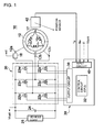
- Fig. 1 is a drawing explaining electrical connection of the three-phase AC generator and the battery charging apparatus.
- a three-phase AC generator (hereinafter referred to as a generator) 10 shown in Fig. 1 is a magnet generator driven by a prime mover such as an internal combustion engine.
- the magnet generator includes a rotator (rotor) 12 in which a magnetic field is formed by attaching permanent magnets to a yoke, and a stationary part (stator) formed of an armature core and armature windings 12u, 12v, 12w wound around the core.
- the rotor is attached to a rotary shaft of the prime mover, and the stator is fixed to an attaching part that is attached to a case, a cover and the like of the prime mover.
- the three-phase power outputted by the armature windings 12u, 12v, 12w of the generator 10 is charged to a battery 24 that is a secondary battery through a regulator 20, and is supplied to a load 26 that is an electrical component in a vehicle.
- a battery 24 that is a secondary battery through a regulator 20
- a load 26 that is an electrical component in a vehicle.
- the regulator 20 formed of a MOS type FET functions as a rectifying/switching circuit that combines a full-wave rectifier and a switching element by a parasitic diode present between the drain and the source of the MOS type FET.
- the regulator 20 applies a control voltage to the armature windings 12u, 12v, 12w through the switching circuit, and controls the output voltage of the generator 10 so as to obtain a voltage appropriate as a charging voltage of the battery 24. Then, the DC voltage obtained by rectifying the three-phase voltage by the full-wave rectifier is supplied to the battery 24 and the load 26.
- Drain terminals of switching elements 22u, 22v, 22w are connected to the positive electrode of the battery 24, and source terminals of these switching elements are connected to output terminals 12a, 12b, 12c of the generator 10 respectively. Also, source terminals of switching elements 22x, 22y, 22z are connected to a negative electrode of the battery 24, and drain terminals of these switching elements are connected to the output terminals 12a, 12b, 12c of the generator 10 respectively.
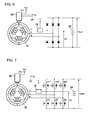
- a current sensor 18 detecting the current and a voltage sensor detecting the voltage of the phase are disposed. Note that the current sensor and the voltage sensor are provided in the embodiment, however either one of them only has to be provided in implementing the invention.
- An inverter control section 30 includes an input circuit 40 that inputs various signals, a control circuit 32 formed of one-chip microcomputers and the like, and an output circuit 38 that outputs a drive signal driving the switching elements of the regulator 20 to gates of the respective switching elements.
- the input circuit 40 inputs a position detection signal Tp outputted by a position sensor 42, a revolution speed signal Ne of the prime mover, a current signal I1 outputted by the current sensor 18, and a battery voltage signal Vbatt.
- a CPU of the control circuit 32 (hereinafter referred to as a CPU 32) achieves various controls by executing programs stored in a ROM with a RAM being a work memory.
- the CPU 32 supplies an open/close signal of each switching element of the regulator 20 to the output circuit 38 based on a signal inputted to the input circuit 40.
- the output circuit 38 outputs a drive signal that opens/closes (on/off) each switching element of the regulator 20 according to the open/close signal, and the energization control of each switching element of the regulator 20 is achieved.
- the drive signal that is, the timing of energization for each switching element is controlled for example by a microcomputer using an energization control map prepared beforehand.
- the phase control is executed in which, when the required current fluctuates due to fluctuation of the charging state of the battery and the load, the timing of energization with respect to each switching element is changed (advancing and retarding the angle).
- the phase control is a control method in which the energization timing of the switching element corresponding to each phase is advanced or retarded with respect to the position detection signal of each phase.
- the CPU 32 When a control voltage is applied to the armature winding 12u, the CPU 32 turns the switching element 22u on, and turns either one or both of the switching elements 22y and 22z on. Also, when a control voltage is applied to the armature winding 12v, the switching element 22v is turned on and either one or both of the switching elements 22x and 22z are turned on. Further, when a control voltage is applied to the armature winding 12w, the switching element 22w is turned on and either one or both of the switching elements 22x and 22y are turned on.
- a reluctor 17 is fixed to the attaching part of the generator 10 for example so as to oppose the reluctor 17, and generates the position detection signal Tp every time the reluctor 17 that rotates along with the rotor 12 passes nearby.
- the reluctor 17 and the position sensor 42 are disposed so that the position detection signal Tp is outputted at the timing the induced voltage of a predetermined phase (the U-phase of the armature winding 12u for example) shifts from a negative voltage to a positive voltage (zero-cross point). Therefore, usually, the output timing of the position detection signal Tp is deemed to agree to the phase of the induced voltage, and the output timing of the switching element is determined based on the phase of the position detection signal Tp as a reference.
- a predetermined phase the U-phase of the armature winding 12u for example
- the energization control can be executed more highly precisely.
- the battery charging apparatus is formed of the position sensor 42, the current sensor 18 (or the voltage sensor), the regulator 20, the inverter control section 30 and the like.
- Fig. 3 is a drawing showing a relation among the position detection signal Tp, the induced voltage E, and the phase of the voltage V2 and the current I1 of the output terminal 12a of the generator 10.
- the phase difference intended to measure is the phase difference ⁇ 3 (the third phase difference) between the dropping of the position detection signal Tp and the zero-cross point of the induced voltage E which is equivalent to the error of the part dimension and the attaching position of the reluctor 17 and the position sensor 42.
- ⁇ 3 the third phase difference
- phase difference ⁇ 1 the first phase difference
- the phase difference ⁇ 2 the second phase difference
- the voltage V2 (the current I1) is obtained by measuring a waveform outputted from the output terminal of the generator as it is. With this regard, three detection methods are possible.
- the energizing control is temporarily suspended (the full-wave rectification state)
- the voltage V2 and the current I1 of Fig. 3 which are the output signals of the predetermined phase can be detected from the voltage sensor or the current sensor.
- the voltage V2 and the current I1 of Fig. 3 which are the output signals of the predetermined phase can be detected from the voltage sensor or the current sensor similarly to the above although height of the waveform becomes shorter compared to those of the time of full-wave rectification.
- phase difference ⁇ 2 (the second phase difference) between the rising of the voltage V2 (the current I1) and the zero-cross point of the induced voltage E will be described.
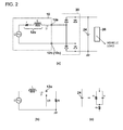
- Fig. 2 is a drawing explaining action of the generator 10 and the battery charging apparatus, and Fig. 2(a) shows only the relation between the U-phase and the battery charging apparatus.
- the voltage E is induced by the change of the magnetic field ⁇ .
- the armature winding 12u is equivalent to the inductance L connected in series to the voltage source (the induced voltage E), and the phase of the current I outputted from the output terminal 12a shows retarding with respect to the phase of the induced voltage E.
- Fig. 2(b) is an equivalent circuit of a configuration shown in Fig. 2(a) , and the resistance value r of the armature winding 12u is ignored because it is sufficiently small (r ⁇ R). Also, because the load side from the regulator 20 is a DC circuit, a reactance component is ignored, and the load side from the regulator 20 is represented by the load resistance value R. That is, the generator 10 and the battery charging apparatus can be deemed as a circuit in which the voltage source E, the inductance L, and the load resistance value R are connected to each other in series. In Fig.
- phase difference ⁇ 3 (the third phase difference) between the dropping of the position detection signal Tp and the zero-cross point of the induced voltage E
- the phase difference ⁇ 1 (the first phase difference) between the dropping of the position detection signal Tp and the rising of the voltage V2 (the current I1)
- the phase difference ⁇ 2 (the second phase difference) between the rising of the voltage V2 (the current I1) and the zero-cross point of the induced voltage E, and the relation therebetween is expressed by the expression below.
- ⁇ ⁇ 3 ⁇ ⁇ 1 - ⁇ ⁇ 2
- phase of the induced voltage E can be detected in a state the output terminal 12a is connected to the regulator 20, and, for the energizing control of each switching element of the regulator 20, precise energizing control based on the position detection signal Tp can be executed.
- the output current of the armature winding shows the maximum.
- the error of the part dimension and the attaching position of the reluctor 17 and the position sensor 42 is included in the position detection signal Tp, and detection of the error is indispensable for execution of precise energization control.
- the voltage V2 between the output terminal 12a of the generator 10 and grounding potential GND generally repeats between the battery voltage and theGND, and it is possible to detect the rising of (or the dropping) of the voltage V2 or the current I1.
- the battery 24 can be deemed to be equivalent to a circuit in which a resistance and a capacitor are combined, and internal impedance of the battery 24 changes according to the charging state, that is, the terminal voltage Vbatt of the battery 24. Therefore, in estimation of the phase difference ⁇ 2, it is desirable to execute correction of the phase difference (hereinafter referred to as the phase difference correction) considering the revolution speed of the generator 10 (the revolution speed signal Ne of the prime mover) and the terminal voltage of the battery 24 (the battery voltage signal Vbatt).
- the phase difference correction considering the revolution speed of the generator 10 (the revolution speed signal Ne of the prime mover) and the terminal voltage of the battery 24 (the battery voltage signal Vbatt).
- Fig. 4 is a drawing showing an example of a correction map for phase difference correction.
- the correction map shows the relation among the revolution speed signal Ne, the battery terminal voltage signal Vbatt, and the phase difference ⁇ 2.
- the battery terminal voltage shown in Fig. 4 has the relation of V1 ⁇ V2 ⁇ V3. That is, the correction map shows the relation between the revolution speed signal Ne and the phase difference ⁇ 2 with the battery terminal voltage signal Vbatt being a parameter, provides the phase difference ⁇ 2 corresponding to the revolution speed signal Ne, and further shows correction of the phase difference ⁇ 2 corresponding to the battery terminal voltage Vbatt.
- the phase difference correction processing is started. It is a matter of course that to start the phase difference correction processing is not necessary when, after the phase difference correction processing is executed in the vicinity of 1,000 rpm for example, the revolution speed signal Ne shows the vicinity of 1,000 rpm again.
- Fig. 5 is a flowchart explaining the phase difference correction processing.
- the CPU 32 executes initialization (S11). That is, a counter N and array variables described below are initialized (a stored value is made 0), a timer is started, the energization control of the regulator 20 is suspended, and each switching element is made an open state.
- the CPU 32 waits for receipt of the position detection signal Tp (S12), and, when the position detection signal Tp is received, stores a count value t of the timer in the array variable PC[N] (S13).
- the CPU 32 determines whether the current signal I1 has risen or not (S14). When the current signal I1 rises, the CPU 32 stores the count value t of the timer in the array variable I1[N], stores the battery terminal voltage signal Vbatt in the array variable VB[N], and stores the revolution speed signal Ne in the array variable NE[N] (S15).
- ⁇ ⁇ 1 PC N - I ⁇ 1 N / P ⁇ 360
- the CPU 32 refers to a correction map 33 based on the value of the array variables VB[N] and NE[N], and calculates the phase difference ⁇ 2 (S19). Then, the CPU 32 stores the difference between the phase difference ⁇ 1 and ⁇ 2 ( ⁇ 1- ⁇ 2) in the array variable ⁇ [N] (S20).
- the CPU 32 determines the count value of the counter N (S21), and, when N ⁇ Nmax, increments the counter N (S22), and returns the processing to the step S12. Also, when the counter value reaches Nmax, the CPU 32 acquires the phase difference ⁇ 3 that is obtained by averaging ⁇ [1] to ⁇ [N] by the expression below (S23), restarts the energization control of the regulator 20 which uses the acquired phase difference ⁇ 3 (S24), and finishes the phase difference correction processing.
- the phase difference correction processing described above the phase difference ⁇ 3 equivalent to the error of the part dimension and the attaching position of the reluctor 17 and the position sensor 42 can be estimated.
- the CPU 32 can precisely execute the energization control of the regulator 20 for using the region of approximately ⁇ 10 degrees for example for charging with respect to the phase where the output current value of the armature winding shows the peak.
- the reason plural estimate values ⁇ 3[1] to ⁇ 3[N] are averaged and the average is made the phase difference ⁇ 3 is that the rotation of the engine is formed of respective strokes of suction, compression, combustion, and exhaust, and that the variation portion according to the strokes is to be removed. That is, estimate values ⁇ 3[1] to ⁇ 3[N] of plural rotations of the generator 10 are averaged, and the phase difference ⁇ 3 in which the variation portion according to respective strokes are removed is obtained. Nmax (number of times of estimation) showing the upper limit of the count value N for the same is made "8" for example.
- phase difference ⁇ 3 obtained is recorded for every rotation speed signal Ne (the revolution speed region) that becomes a trigger for process start, and the phase difference ⁇ 3 estimated in a high revolution speed region where the rotation of the engine is stabilized more is preferentially used for the energization control.
- the revolution speed at finer timing can be calculated compared with the case the revolution speed Ne is calculated from the position detection signal Tp, the phase difference ⁇ 3 can be estimated more precisely.
- the error of the attaching position of the sensor can be detected in executing the energization control of each phase based on the sensor signal that detects rotation of the rotor of the generator, and therefore the energization control of each phase can be executed appropriately.
Landscapes
- Engineering & Computer Science (AREA)
- Life Sciences & Earth Sciences (AREA)
- Sustainable Development (AREA)
- Sustainable Energy (AREA)
- Power Engineering (AREA)
- Transportation (AREA)
- Mechanical Engineering (AREA)
- Control Of Eletrric Generators (AREA)
Applications Claiming Priority (1)
| Application Number | Priority Date | Filing Date | Title |
|---|---|---|---|
| JP2013080813A JP6117599B2 (ja) | 2013-04-08 | 2013-04-08 | 車両用バッテリ充電装置 |
Publications (3)
| Publication Number | Publication Date |
|---|---|
| EP2789494A2 true EP2789494A2 (fr) | 2014-10-15 |
| EP2789494A3 EP2789494A3 (fr) | 2014-11-26 |
| EP2789494B1 EP2789494B1 (fr) | 2018-08-22 |
Family
ID=50112804
Family Applications (1)
| Application Number | Title | Priority Date | Filing Date |
|---|---|---|---|
| EP14155386.7A Active EP2789494B1 (fr) | 2013-04-08 | 2014-02-17 | Appareil de charge de batterie pour véhicule |
Country Status (4)
| Country | Link |
|---|---|
| US (1) | US9290099B2 (fr) |
| EP (1) | EP2789494B1 (fr) |
| JP (1) | JP6117599B2 (fr) |
| ES (1) | ES2685647T3 (fr) |
Families Citing this family (5)
| Publication number | Priority date | Publication date | Assignee | Title |
|---|---|---|---|---|
| JP6301240B2 (ja) * | 2014-02-07 | 2018-03-28 | 本田技研工業株式会社 | 車両用バッテリ充電装置 |
| WO2016151851A1 (fr) * | 2015-03-26 | 2016-09-29 | 新電元工業株式会社 | Dispositif de charge de batterie et procédé de commande de dispositif de charge de batterie |
| JP6969464B2 (ja) * | 2018-03-19 | 2021-11-24 | トヨタ自動車株式会社 | 二次電池システムおよび二次電池の劣化状態推定方法 |
| DE102019114073A1 (de) * | 2019-05-27 | 2020-12-03 | Ebm-Papst Mulfingen Gmbh & Co. Kg | Sensorloses Kommutierungsverfahren |
| US12576738B2 (en) * | 2022-06-14 | 2026-03-17 | Universal City Studios Llc | Docked interlock system and method |
Citations (1)
| Publication number | Priority date | Publication date | Assignee | Title |
|---|---|---|---|---|
| JP2012060705A (ja) | 2010-09-06 | 2012-03-22 | Honda Motor Co Ltd | 電動車両駆動用モータの出力制御装置および出力制御方法 |
Family Cites Families (6)
| Publication number | Priority date | Publication date | Assignee | Title |
|---|---|---|---|---|
| JP4560710B2 (ja) * | 2004-05-28 | 2010-10-13 | 富士電機システムズ株式会社 | 発電システム |
| JP2007312469A (ja) * | 2006-05-17 | 2007-11-29 | Hitachi Ltd | 車載電源システム及車載電源用発電機並びにその制御装置 |
| JP4894417B2 (ja) * | 2006-08-30 | 2012-03-14 | 国産電機株式会社 | 発電装置 |
| JP4434217B2 (ja) * | 2007-02-14 | 2010-03-17 | 株式会社デンソー | 充電制御装置 |
| US8378623B2 (en) * | 2010-11-05 | 2013-02-19 | General Electric Company | Apparatus and method for charging an electric vehicle |
| WO2013009711A1 (fr) * | 2011-07-08 | 2013-01-17 | Timler John P | Isolateur basé sur une ou plusieurs structures diélectriques |
-
2013
- 2013-04-08 JP JP2013080813A patent/JP6117599B2/ja active Active
-
2014
- 2014-02-17 EP EP14155386.7A patent/EP2789494B1/fr active Active
- 2014-02-17 ES ES14155386.7T patent/ES2685647T3/es active Active
- 2014-03-28 US US14/228,505 patent/US9290099B2/en active Active
Patent Citations (1)
| Publication number | Priority date | Publication date | Assignee | Title |
|---|---|---|---|---|
| JP2012060705A (ja) | 2010-09-06 | 2012-03-22 | Honda Motor Co Ltd | 電動車両駆動用モータの出力制御装置および出力制御方法 |
Also Published As
| Publication number | Publication date |
|---|---|
| JP6117599B2 (ja) | 2017-04-19 |
| US20140300318A1 (en) | 2014-10-09 |
| EP2789494A3 (fr) | 2014-11-26 |
| US9290099B2 (en) | 2016-03-22 |
| ES2685647T3 (es) | 2018-10-10 |
| EP2789494B1 (fr) | 2018-08-22 |
| JP2014204620A (ja) | 2014-10-27 |
Similar Documents
| Publication | Publication Date | Title |
|---|---|---|
| US7683587B2 (en) | Generation device | |
| US7081738B2 (en) | Generating device having magneto generator | |
| US6940259B2 (en) | Generating device including magneto generator | |
| US7253590B2 (en) | Output control device of generation device | |
| EP2706657B1 (fr) | Dispositif de commande de moteur sans balai et procédé de commande de moteur sans balai | |
| EP2789494B1 (fr) | Appareil de charge de batterie pour véhicule | |
| US20130271051A1 (en) | Hybrid Electric Vehicle System and Method of Controlling The Same | |
| EP2824826B1 (fr) | Dispositif de génération de puissance, objet mobile et procédé de commande de génération de puissance | |
| US9614397B2 (en) | Battery charging apparatus for vehicle | |
| JP5569032B2 (ja) | 車両用異常検出装置 | |
| JP4196637B2 (ja) | 内燃機関駆動発電装置 | |
| US20130257353A1 (en) | Battery charging apparatus | |
| WO2018097014A1 (fr) | Dispositif de détection de défaillance pour détecteur de rotation | |
| JP6059064B2 (ja) | 発電制御装置 | |
| JP6948845B2 (ja) | 電子制御装置 | |
| JP6967880B2 (ja) | 電子制御装置 | |
| JP6933919B2 (ja) | 電子制御装置 | |
| JP2018204554A (ja) | エンジンの始動装置 |
Legal Events
| Date | Code | Title | Description |
|---|---|---|---|
| PUAI | Public reference made under article 153(3) epc to a published international application that has entered the european phase |
Free format text: ORIGINAL CODE: 0009012 |
|
| 17P | Request for examination filed |
Effective date: 20140217 |
|
| AK | Designated contracting states |
Kind code of ref document: A2 Designated state(s): AL AT BE BG CH CY CZ DE DK EE ES FI FR GB GR HR HU IE IS IT LI LT LU LV MC MK MT NL NO PL PT RO RS SE SI SK SM TR |
|
| AX | Request for extension of the european patent |
Extension state: BA ME |
|
| PUAL | Search report despatched |
Free format text: ORIGINAL CODE: 0009013 |
|
| AK | Designated contracting states |
Kind code of ref document: A3 Designated state(s): AL AT BE BG CH CY CZ DE DK EE ES FI FR GB GR HR HU IE IS IT LI LT LU LV MC MK MT NL NO PL PT RO RS SE SI SK SM TR |
|
| AX | Request for extension of the european patent |
Extension state: BA ME |
|
| RIC1 | Information provided on ipc code assigned before grant |
Ipc: B60L 3/00 20060101AFI20141022BHEP Ipc: B60L 11/12 20060101ALI20141022BHEP Ipc: B60L 11/02 20060101ALI20141022BHEP Ipc: B60L 11/18 20060101ALI20141022BHEP |
|
| STAA | Information on the status of an ep patent application or granted ep patent |
Free format text: STATUS: EXAMINATION IS IN PROGRESS |
|
| 17Q | First examination report despatched |
Effective date: 20170502 |
|
| GRAP | Despatch of communication of intention to grant a patent |
Free format text: ORIGINAL CODE: EPIDOSNIGR1 |
|
| STAA | Information on the status of an ep patent application or granted ep patent |
Free format text: STATUS: GRANT OF PATENT IS INTENDED |
|
| INTG | Intention to grant announced |
Effective date: 20180312 |
|
| GRAS | Grant fee paid |
Free format text: ORIGINAL CODE: EPIDOSNIGR3 |
|
| GRAA | (expected) grant |
Free format text: ORIGINAL CODE: 0009210 |
|
| STAA | Information on the status of an ep patent application or granted ep patent |
Free format text: STATUS: THE PATENT HAS BEEN GRANTED |
|
| AK | Designated contracting states |
Kind code of ref document: B1 Designated state(s): AL AT BE BG CH CY CZ DE DK EE ES FI FR GB GR HR HU IE IS IT LI LT LU LV MC MK MT NL NO PL PT RO RS SE SI SK SM TR |
|
| REG | Reference to a national code |
Ref country code: GB Ref legal event code: FG4D |
|
| REG | Reference to a national code |
Ref country code: CH Ref legal event code: EP |
|
| REG | Reference to a national code |
Ref country code: AT Ref legal event code: REF Ref document number: 1032045 Country of ref document: AT Kind code of ref document: T Effective date: 20180915 |
|
| REG | Reference to a national code |
Ref country code: IE Ref legal event code: FG4D |
|
| REG | Reference to a national code |
Ref country code: DE Ref legal event code: R096 Ref document number: 602014030713 Country of ref document: DE |
|
| REG | Reference to a national code |
Ref country code: ES Ref legal event code: FG2A Ref document number: 2685647 Country of ref document: ES Kind code of ref document: T3 Effective date: 20181010 |
|
| REG | Reference to a national code |
Ref country code: NL Ref legal event code: MP Effective date: 20180822 |
|
| REG | Reference to a national code |
Ref country code: LT Ref legal event code: MG4D |
|
| PG25 | Lapsed in a contracting state [announced via postgrant information from national office to epo] |
Ref country code: NL Free format text: LAPSE BECAUSE OF FAILURE TO SUBMIT A TRANSLATION OF THE DESCRIPTION OR TO PAY THE FEE WITHIN THE PRESCRIBED TIME-LIMIT Effective date: 20180822 Ref country code: RS Free format text: LAPSE BECAUSE OF FAILURE TO SUBMIT A TRANSLATION OF THE DESCRIPTION OR TO PAY THE FEE WITHIN THE PRESCRIBED TIME-LIMIT Effective date: 20180822 Ref country code: SE Free format text: LAPSE BECAUSE OF FAILURE TO SUBMIT A TRANSLATION OF THE DESCRIPTION OR TO PAY THE FEE WITHIN THE PRESCRIBED TIME-LIMIT Effective date: 20180822 Ref country code: NO Free format text: LAPSE BECAUSE OF FAILURE TO SUBMIT A TRANSLATION OF THE DESCRIPTION OR TO PAY THE FEE WITHIN THE PRESCRIBED TIME-LIMIT Effective date: 20181122 Ref country code: IS Free format text: LAPSE BECAUSE OF FAILURE TO SUBMIT A TRANSLATION OF THE DESCRIPTION OR TO PAY THE FEE WITHIN THE PRESCRIBED TIME-LIMIT Effective date: 20181222 Ref country code: LT Free format text: LAPSE BECAUSE OF FAILURE TO SUBMIT A TRANSLATION OF THE DESCRIPTION OR TO PAY THE FEE WITHIN THE PRESCRIBED TIME-LIMIT Effective date: 20180822 Ref country code: BG Free format text: LAPSE BECAUSE OF FAILURE TO SUBMIT A TRANSLATION OF THE DESCRIPTION OR TO PAY THE FEE WITHIN THE PRESCRIBED TIME-LIMIT Effective date: 20181122 Ref country code: GR Free format text: LAPSE BECAUSE OF FAILURE TO SUBMIT A TRANSLATION OF THE DESCRIPTION OR TO PAY THE FEE WITHIN THE PRESCRIBED TIME-LIMIT Effective date: 20181123 Ref country code: FI Free format text: LAPSE BECAUSE OF FAILURE TO SUBMIT A TRANSLATION OF THE DESCRIPTION OR TO PAY THE FEE WITHIN THE PRESCRIBED TIME-LIMIT Effective date: 20180822 |
|
| REG | Reference to a national code |
Ref country code: AT Ref legal event code: MK05 Ref document number: 1032045 Country of ref document: AT Kind code of ref document: T Effective date: 20180822 |
|
| PG25 | Lapsed in a contracting state [announced via postgrant information from national office to epo] |
Ref country code: LV Free format text: LAPSE BECAUSE OF FAILURE TO SUBMIT A TRANSLATION OF THE DESCRIPTION OR TO PAY THE FEE WITHIN THE PRESCRIBED TIME-LIMIT Effective date: 20180822 Ref country code: AL Free format text: LAPSE BECAUSE OF FAILURE TO SUBMIT A TRANSLATION OF THE DESCRIPTION OR TO PAY THE FEE WITHIN THE PRESCRIBED TIME-LIMIT Effective date: 20180822 Ref country code: HR Free format text: LAPSE BECAUSE OF FAILURE TO SUBMIT A TRANSLATION OF THE DESCRIPTION OR TO PAY THE FEE WITHIN THE PRESCRIBED TIME-LIMIT Effective date: 20180822 |
|
| PG25 | Lapsed in a contracting state [announced via postgrant information from national office to epo] |
Ref country code: RO Free format text: LAPSE BECAUSE OF FAILURE TO SUBMIT A TRANSLATION OF THE DESCRIPTION OR TO PAY THE FEE WITHIN THE PRESCRIBED TIME-LIMIT Effective date: 20180822 Ref country code: EE Free format text: LAPSE BECAUSE OF FAILURE TO SUBMIT A TRANSLATION OF THE DESCRIPTION OR TO PAY THE FEE WITHIN THE PRESCRIBED TIME-LIMIT Effective date: 20180822 Ref country code: AT Free format text: LAPSE BECAUSE OF FAILURE TO SUBMIT A TRANSLATION OF THE DESCRIPTION OR TO PAY THE FEE WITHIN THE PRESCRIBED TIME-LIMIT Effective date: 20180822 Ref country code: PL Free format text: LAPSE BECAUSE OF FAILURE TO SUBMIT A TRANSLATION OF THE DESCRIPTION OR TO PAY THE FEE WITHIN THE PRESCRIBED TIME-LIMIT Effective date: 20180822 Ref country code: CZ Free format text: LAPSE BECAUSE OF FAILURE TO SUBMIT A TRANSLATION OF THE DESCRIPTION OR TO PAY THE FEE WITHIN THE PRESCRIBED TIME-LIMIT Effective date: 20180822 |
|
| PGFP | Annual fee paid to national office [announced via postgrant information from national office to epo] |
Ref country code: ES Payment date: 20190301 Year of fee payment: 6 |
|
| REG | Reference to a national code |
Ref country code: DE Ref legal event code: R097 Ref document number: 602014030713 Country of ref document: DE |
|
| PG25 | Lapsed in a contracting state [announced via postgrant information from national office to epo] |
Ref country code: SM Free format text: LAPSE BECAUSE OF FAILURE TO SUBMIT A TRANSLATION OF THE DESCRIPTION OR TO PAY THE FEE WITHIN THE PRESCRIBED TIME-LIMIT Effective date: 20180822 Ref country code: SK Free format text: LAPSE BECAUSE OF FAILURE TO SUBMIT A TRANSLATION OF THE DESCRIPTION OR TO PAY THE FEE WITHIN THE PRESCRIBED TIME-LIMIT Effective date: 20180822 Ref country code: DK Free format text: LAPSE BECAUSE OF FAILURE TO SUBMIT A TRANSLATION OF THE DESCRIPTION OR TO PAY THE FEE WITHIN THE PRESCRIBED TIME-LIMIT Effective date: 20180822 |
|
| PLBE | No opposition filed within time limit |
Free format text: ORIGINAL CODE: 0009261 |
|
| STAA | Information on the status of an ep patent application or granted ep patent |
Free format text: STATUS: NO OPPOSITION FILED WITHIN TIME LIMIT |
|
| 26N | No opposition filed |
Effective date: 20190523 |
|
| PG25 | Lapsed in a contracting state [announced via postgrant information from national office to epo] |
Ref country code: SI Free format text: LAPSE BECAUSE OF FAILURE TO SUBMIT A TRANSLATION OF THE DESCRIPTION OR TO PAY THE FEE WITHIN THE PRESCRIBED TIME-LIMIT Effective date: 20180822 |
|
| REG | Reference to a national code |
Ref country code: CH Ref legal event code: PL |
|
| GBPC | Gb: european patent ceased through non-payment of renewal fee |
Effective date: 20190217 |
|
| PG25 | Lapsed in a contracting state [announced via postgrant information from national office to epo] |
Ref country code: LU Free format text: LAPSE BECAUSE OF NON-PAYMENT OF DUE FEES Effective date: 20190217 Ref country code: MC Free format text: LAPSE BECAUSE OF FAILURE TO SUBMIT A TRANSLATION OF THE DESCRIPTION OR TO PAY THE FEE WITHIN THE PRESCRIBED TIME-LIMIT Effective date: 20180822 |
|
| REG | Reference to a national code |
Ref country code: BE Ref legal event code: MM Effective date: 20190228 |
|
| REG | Reference to a national code |
Ref country code: IE Ref legal event code: MM4A |
|
| REG | Reference to a national code |
Ref country code: DE Ref legal event code: R084 Ref document number: 602014030713 Country of ref document: DE |
|
| PG25 | Lapsed in a contracting state [announced via postgrant information from national office to epo] |
Ref country code: CH Free format text: LAPSE BECAUSE OF NON-PAYMENT OF DUE FEES Effective date: 20190228 Ref country code: LI Free format text: LAPSE BECAUSE OF NON-PAYMENT OF DUE FEES Effective date: 20190228 |
|
| PG25 | Lapsed in a contracting state [announced via postgrant information from national office to epo] |
Ref country code: IE Free format text: LAPSE BECAUSE OF NON-PAYMENT OF DUE FEES Effective date: 20190217 Ref country code: GB Free format text: LAPSE BECAUSE OF NON-PAYMENT OF DUE FEES Effective date: 20190217 |
|
| PG25 | Lapsed in a contracting state [announced via postgrant information from national office to epo] |
Ref country code: BE Free format text: LAPSE BECAUSE OF NON-PAYMENT OF DUE FEES Effective date: 20190228 Ref country code: FR Free format text: LAPSE BECAUSE OF NON-PAYMENT OF DUE FEES Effective date: 20190228 |
|
| PG25 | Lapsed in a contracting state [announced via postgrant information from national office to epo] |
Ref country code: TR Free format text: LAPSE BECAUSE OF FAILURE TO SUBMIT A TRANSLATION OF THE DESCRIPTION OR TO PAY THE FEE WITHIN THE PRESCRIBED TIME-LIMIT Effective date: 20180822 |
|
| PGFP | Annual fee paid to national office [announced via postgrant information from national office to epo] |
Ref country code: IT Payment date: 20200128 Year of fee payment: 7 |
|
| PG25 | Lapsed in a contracting state [announced via postgrant information from national office to epo] |
Ref country code: PT Free format text: LAPSE BECAUSE OF FAILURE TO SUBMIT A TRANSLATION OF THE DESCRIPTION OR TO PAY THE FEE WITHIN THE PRESCRIBED TIME-LIMIT Effective date: 20181222 Ref country code: MT Free format text: LAPSE BECAUSE OF NON-PAYMENT OF DUE FEES Effective date: 20190217 |
|
| PG25 | Lapsed in a contracting state [announced via postgrant information from national office to epo] |
Ref country code: CY Free format text: LAPSE BECAUSE OF FAILURE TO SUBMIT A TRANSLATION OF THE DESCRIPTION OR TO PAY THE FEE WITHIN THE PRESCRIBED TIME-LIMIT Effective date: 20180822 |
|
| REG | Reference to a national code |
Ref country code: ES Ref legal event code: FD2A Effective date: 20210705 |
|
| PG25 | Lapsed in a contracting state [announced via postgrant information from national office to epo] |
Ref country code: HU Free format text: LAPSE BECAUSE OF FAILURE TO SUBMIT A TRANSLATION OF THE DESCRIPTION OR TO PAY THE FEE WITHIN THE PRESCRIBED TIME-LIMIT; INVALID AB INITIO Effective date: 20140217 |
|
| PG25 | Lapsed in a contracting state [announced via postgrant information from national office to epo] |
Ref country code: ES Free format text: LAPSE BECAUSE OF NON-PAYMENT OF DUE FEES Effective date: 20200218 |
|
| PG25 | Lapsed in a contracting state [announced via postgrant information from national office to epo] |
Ref country code: IT Free format text: LAPSE BECAUSE OF NON-PAYMENT OF DUE FEES Effective date: 20210217 |
|
| PG25 | Lapsed in a contracting state [announced via postgrant information from national office to epo] |
Ref country code: MK Free format text: LAPSE BECAUSE OF FAILURE TO SUBMIT A TRANSLATION OF THE DESCRIPTION OR TO PAY THE FEE WITHIN THE PRESCRIBED TIME-LIMIT Effective date: 20180822 |
|
| PGFP | Annual fee paid to national office [announced via postgrant information from national office to epo] |
Ref country code: DE Payment date: 20260121 Year of fee payment: 13 |