EP2789770B1 - Gleitlager für Teleskopausleger, insbesondere für Spritzbetonhandhabungsmittel oder -roboter - Google Patents
Gleitlager für Teleskopausleger, insbesondere für Spritzbetonhandhabungsmittel oder -roboter Download PDFInfo
- Publication number
- EP2789770B1 EP2789770B1 EP13163149.1A EP13163149A EP2789770B1 EP 2789770 B1 EP2789770 B1 EP 2789770B1 EP 13163149 A EP13163149 A EP 13163149A EP 2789770 B1 EP2789770 B1 EP 2789770B1
- Authority
- EP
- European Patent Office
- Prior art keywords
- section
- arm
- slide
- slide bearing
- sections
- Prior art date
- Legal status (The legal status is an assumption and is not a legal conclusion. Google has not performed a legal analysis and makes no representation as to the accuracy of the status listed.)
- Not-in-force
Links
Images




Classifications
-
- B—PERFORMING OPERATIONS; TRANSPORTING
- B66—HOISTING; LIFTING; HAULING
- B66C—CRANES; LOAD-ENGAGING ELEMENTS OR DEVICES FOR CRANES, CAPSTANS, WINCHES, OR TACKLES
- B66C23/00—Cranes comprising essentially a beam, boom, or triangular structure acting as a cantilever and mounted for translatory of swinging movements in vertical or horizontal planes or a combination of such movements, e.g. jib-cranes, derricks, tower cranes
- B66C23/62—Constructional features or details
- B66C23/64—Jibs
- B66C23/70—Jibs constructed of sections adapted to be assembled to form jibs or various lengths
- B66C23/701—Jibs constructed of sections adapted to be assembled to form jibs or various lengths telescopic
- B66C23/707—Jibs constructed of sections adapted to be assembled to form jibs or various lengths telescopic guiding devices for telescopic jibs
-
- F—MECHANICAL ENGINEERING; LIGHTING; HEATING; WEAPONS; BLASTING
- F16—ENGINEERING ELEMENTS AND UNITS; GENERAL MEASURES FOR PRODUCING AND MAINTAINING EFFECTIVE FUNCTIONING OF MACHINES OR INSTALLATIONS; THERMAL INSULATION IN GENERAL
- F16C—SHAFTS; FLEXIBLE SHAFTS; ELEMENTS OR CRANKSHAFT MECHANISMS; ROTARY BODIES OTHER THAN GEARING ELEMENTS; BEARINGS
- F16C29/00—Bearings for parts moving only linearly
- F16C29/02—Sliding-contact bearings
-
- F—MECHANICAL ENGINEERING; LIGHTING; HEATING; WEAPONS; BLASTING
- F16—ENGINEERING ELEMENTS AND UNITS; GENERAL MEASURES FOR PRODUCING AND MAINTAINING EFFECTIVE FUNCTIONING OF MACHINES OR INSTALLATIONS; THERMAL INSULATION IN GENERAL
- F16C—SHAFTS; FLEXIBLE SHAFTS; ELEMENTS OR CRANKSHAFT MECHANISMS; ROTARY BODIES OTHER THAN GEARING ELEMENTS; BEARINGS
- F16C3/00—Shafts; Axles; Cranks; Eccentrics
- F16C3/02—Shafts; Axles
- F16C3/03—Shafts; Axles telescopic
- F16C3/035—Shafts; Axles telescopic with built-in bearings
-
- F—MECHANICAL ENGINEERING; LIGHTING; HEATING; WEAPONS; BLASTING
- F16—ENGINEERING ELEMENTS AND UNITS; GENERAL MEASURES FOR PRODUCING AND MAINTAINING EFFECTIVE FUNCTIONING OF MACHINES OR INSTALLATIONS; THERMAL INSULATION IN GENERAL
- F16C—SHAFTS; FLEXIBLE SHAFTS; ELEMENTS OR CRANKSHAFT MECHANISMS; ROTARY BODIES OTHER THAN GEARING ELEMENTS; BEARINGS
- F16C2208/00—Plastics; Synthetic resins, e.g. rubbers
- F16C2208/10—Elastomers; Rubbers
-
- F—MECHANICAL ENGINEERING; LIGHTING; HEATING; WEAPONS; BLASTING
- F16—ENGINEERING ELEMENTS AND UNITS; GENERAL MEASURES FOR PRODUCING AND MAINTAINING EFFECTIVE FUNCTIONING OF MACHINES OR INSTALLATIONS; THERMAL INSULATION IN GENERAL
- F16C—SHAFTS; FLEXIBLE SHAFTS; ELEMENTS OR CRANKSHAFT MECHANISMS; ROTARY BODIES OTHER THAN GEARING ELEMENTS; BEARINGS
- F16C2208/00—Plastics; Synthetic resins, e.g. rubbers
- F16C2208/20—Thermoplastic resins
- F16C2208/60—Polyamides [PA]
Definitions
- the present invention relates to a slide bearing for telescopic booms, which are extendable and retractable under load and which comprise a plurality of arm sections being movable with respect to each other.
- the present invention relates in particular to a slide bearing for telescopic booms or arms which are used for shotcrete manipulators or robots.
- Shotcrete manipulators or robots comprise a spraying boom comprising a telescopic structure to adapt the spraying nozzle to the local area where the shotcrete should be sprayed.
- the distance of the spraying nozzle from the area the shotcrete should be sprayed on should be in a range of 0.8 to 1.5 m. In use, there is a constant movement of the arm sections of the telescopic arm to bring the spray nozzle into the distance range for spraying.
- the bearings for the arm sections of the telescopic arm conventionally are slide bearings comprising slide plates. These slide plates suffer enormous wear and tear caused by contamination with sticky shotcrete on exposed areas.
- US 4,264,265 for example discloses a telescopic boom with slide bearings, wherein the slide plate of the bearing is biased towards an adjacent boom section by means of a piston arranged within the housing of the bearing and by biasing means in form of a belleville spring. As the slide surface of the slide plate begins to wear, the biasing means will force the slide surface into contact with the surface of the adjacent boom section.
- the slide bearing comprises a first section in form of a housing, comprising a central recess, being adapted to receive a second and a third section, a second section being received in said central recess of said first housing section, and a third section, being smoothly in contact with said second section and comprising a sliding surface, said third section serving as slide plate of the slide bearing (27).
- said second section comprises a central inner recess opening to the bottom of the central recess of the first section and extending into said second section until a base section thereof. Furthermore, said second section is configured such that it provides a load deflection curve starting from a rather flat part and turning into and ending in a very steep part.
- the slide bearings can be incorporated into the boom sections of the telescopic booms under preload avoiding any air gap between the slide plate and the sliding surface resulting in longer life time of the slide plates as entrance of sticky shotcrete between the slide plates and the sliding surfaces of the boom sections is drastically reduced or even avoided.
- the slide bearings of the present invention provide also the advantage that local overload of slide plates as a consequence of non-given parallelism of slide plates and sliding surface, causing deformation or damage of the slide plates and faster wear and tear is avoided.
- the sliding plates of the sliding bearings of the present invention are able to spherically adapt to the sliding surface of the corresponding boom section in order to distribute the load homogenously.
- free movement of the slide plate to essentially adapt its sliding surface to the opposing surface of the inner wall of the corresponding boom section is achieved. Therefore, an uneven load distribution resulting in load peaks above the permissible limits and the mechanical damage caused therefrom is also avoided.
- the second section of the slide bearing is configured such that it provides a load deflection curve which essentially shows an exponential increase.
- said inner recess of said second section comprises an essentially curved shape, in particular a semi-spherical shape.
- said central inner recess of said second section is step-shaped with an inner smaller and an outer greater cross-section, so that said second section is configured such that it provides three load deflection curve parts, said rather flat one being provided by the outer greater step section, a steeper one being provided by the inner step section and said very steep one being provided by the base section of said second section.
- the slide bearing of the present invention provides the following elastic properties of a damped slide plate:
- the second section of the slide bearing of the present invention is formed of the elastomer material, in particular of Elastomer NBR 70.
- the third section forming the slide plate is formed of a polyamide material, in particular, of PA 6 G Mo material.
- the first, second and third sections are of cylindrical shape. Due to this configuration, the slide bearing can be incorporated in drilled openings of the arm sections of the telescopic arm.
- the first section comprises an external thread extending at least partially along the outer circumference of the first section.
- the slide bearing of the present invention can be screwed into a respective threaded bore or opening in the wall of the boom or arm section of the telescopic boom or arm and can be easily adapted to provide the correct placement with respect to the sliding surface of the moveable arm section. Furthermore, easy readjustment or exchange of worn slide plates is also achieved.
- said first section comprising a base section in which a plurality of recesses extend from the side opposite to the side of the central recess of the first section, said recesses being provided under even distance around the circumference of the base section and are able to receive a respective mounting tool.
- a mounting tool may comprise a plurality of pins fitting into the recesses of the first section to turn the first section for mounting, readjustment or exchange purposes of the slide bearing and/or worn parts thereof.
- a plurality of flat sections at the outer circumference of the base section of the first section to cooperate with at least one security means against rotary movement of the first section, said flat sections are provided adjacent to the corresponding recess in the base section of the first section.
- Contact of security means on at least one flat section provides security of the adjusted slide bearing position in the respective arm section of the telescopic arm.
- the slide surface of the third section comprises a sharp edge providing a wiping effect when coming in contact with dirt, shotcrete, etc. despite all precautions.
- the present invention is also directed to a telescopic boom or arm comprising a plurality of boom or arm sections being moveable with respect to each other, which are able to extend or retract under load. It should be noted that telescopic booms or arms of truck mounted cranes are not able to extend or retract under load but are fixed in there position when in operation.
- the arm sections of the telescopic arm of the present invention comprise said slide bearings of the present invention.
- the boom or arm sections of the present invention comprise a polygonal, in particular a hexagonal or octagonal cross section, each boom or arm section comprising two tapering upper and lower wall sections in which the slide bearings are positioned or cooperate with opposite slide surfaces, respectively. With this positioning a very stable configuration of the boom or arm sections to each other is achieved.
- the slide bearings are mounted under preload against the corresponding sliding surfaces of the respective boom or arm sections. Accordingly, contact between the slide plate and the corresponding sliding surface is maintained at all operational conditions, so that any dirt is prevented from entering between the slide plate and the sliding surface.
- the present invention relates to a shotcrete manipulator or robot, comprising a bearing and fixing unit of a telescopic boom or arm and a shotcrete nozzle device, which is provided at one end of the telescopic boom or arm, said telescopic boom or arm is configured according to anyone of the claims 12 to 14.
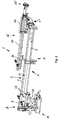
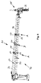
- a shotcrete manipulator or robot 1 comprising a telescopic arm 3 comprising three arm sections 5, 7 and 9, being moveable with respect to each other.
- the position of the arms 7 and 9 show a first expanded position of the telescopic arm 3, with an expanded arm section 7 and a retracted arm section 9.
- Arm section 7 can also be moved in a retracted position within arm section 5.
- the bearing and fixing unit 11 comprises a hydraulic cylinder 13 with which the arm section 5 can angularly be moved upward and downward.
- the forward arm section 9 carries a lance section 15 with a moveable lance 17 mounted in a bearing section 19, which itself is rotateably mounted on a lance carriage section 21 at the front end of the arm section 9 in a conventionally known matter.
- Lance 17 is moveable with respect to bearing section 19 and is driven by a driving chain 23, partly shown in Figs. 1 and 2 .
- a shotcrete nozzle 25 distributing the shotcrete to the chosen areas. These areas are for example freshly excavated interior surfaces of tunnels which, after drilling, need to be immediately covered by shotcrete.
- shotcrete comprising additives which harden the shotcrete in a very short time.
- a distance of the shotcrete nozzle 25 from the respective area should be in the range of 0.8 to 1.5 m. Accordingly, in order to cover the inner surface of the excavated tunnel opening the shotcrete nozzle 25 has to follow with above said distance the inner surface of the freshly excavated tunnel. Accordingly, during operation of the shotcrete nozzle 25 arm sections 7 and 9 as well as moveable lance 17 will almost move constantly to bring shotcrete nozzle 25 into the appropriate position.
- FIG. 4 there is shown in perspective view a slide bearing 27 according to the present invention from the side of the slide plate 29.
- the slide plate 29 forms the third section of the slide bearing 27 and is positioned within a recess 31 of a first section 30 forming a housing of the slide bearing 27.
- the first section 30 is preferably made of non-corrosive steel with minimum tensile strength Rm > 500 MPa, in particular steel number 1.404 or alternatively for example 1.4311, 1.4301 or 1.4541.
- the first section comprises an external thread 33 and a plurality of flat sections 35 at the outer circumference of the first section 30, which are provided to cooperate with at least one security means (not shown), for example a screw, which is applied in close contact against at least one flat section to provide a safe position of the first section 30 against rotary movement of the first section 30.
- at least one security means for example a screw
- Fig. 5 the slide bearing 27 according to the present invention is shown in perspective view from the opposite side as shown in Fig. 4 .
- the first section 30 comprises a base section 37 in which a plurality of recesses 39 is provided. These recesses 39 coincide with the flat sections 35 to indicate the user of the inventive slide bearing 27 the position of the flat sections 35 when mounting the slide bearing 27 into respective threaded bores into the arm sections of the shotcrete manipulator or robot.
- Recesses 39 serve for connection with a mounting tool (not shown) which is provided with pins to be introduced into recesses 39, so that slide bearing 27 can be turned into respective threaded bores of the arm sections 5, 7 and 9 of the telescopic arm 3 as shown in Figs. 1 and 2 .
- FIGs. 6 and 7 there is shown in part cross section and in full cross section a first alternative embodiment of the slide bearing 27 of the present invention.
- a second section 32 comprising an inner recess 41, which is open to the bottom or base section 37 of the first section 30.
- the recess 41 of this embodiment has a step-shaped configuration with an inner smaller recess section 43 and an outer greater recess section 45.
- Second section 32 is made of elastomer material, in particular of the material Elastomer NBR 70. According to the specific configuration of the second section 32, this second section 32 provides three load deflection curves or spring characteristics: According to the greater recess section 45 the second section 32 provides a flat load deflection curve, which provides the possibility of the slide bearing 27 to adapt to manufacturing tolerances of the telescopic arm sections 5 to 9.
- the second section 32 provides a load deflection curve which is steeper than the load deflection curve of greater recess section 45. Accordingly, the second section 32 provides adaptation and in particular compensation of manufacturing tolerances of the arm sections 5 to 9.
- the second section 32 comprises a base section 42 being of full cylindrical shape and providing a very steep load deflection curve or spring characteristic to provide a block and a damp against mechanical impact.
- Slide plate 29 forms the third section which is preferably formed of a polyamide material, in particular of PA 6 G Mo material.
- the third section 29 in form of a slide plate comprises a slide surface 47 with a sharp edge 49 for preventing entry of dirt, in particular sticky shotcrete into the space between the slide surface 47 and the corresponding surface of the arm section of the telescopic arm 3.
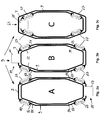
- FIG. 3a to 3c schematic views of cross sections of the shotcrete manipulator or robot of Figs. 1 and 2 are shown, however not showing the real cross sections with dimensions of the sections with respect to each other.
- Figs. 3a to 3c three different parts A, B and C of the telescopic arm 3 are shown.
- Fig. 3a shows the position A indicated in Figs. 1 and 2 showing the slide bearings 27 screwed into the outer arm section 7 to provide the sliding bearing for inner arm section 9.
- the outer arm section comprises upper tapering wall sections 51 in which slide bearings 27 are screwed in and comprises lower tapering wall sections 53 in which slide bearings 27 are screwed in as well.
- These slide bearings 27 give a contact to corresponding upper wall sections 52 of arm section 9 and lower tapering wall sections 54 of arm section 9.
- a roller 57 is provided forming a roll bearing 55 to support arm section 9 when moving out of arm section 7 and in again. This roller compensates the main forces acting on the bearing position.
- Slide bearings 27 are mounted under preload against upper and lower tapering wall sections 52 and 54 leaving no gap between the corresponding sliding surfaces and compensating any manufacturing tolerances of the arm section 7 and 9.
- Fig 3b shows the position B of Fig. 1 and 2 of the arm sections 7 and 9.
- a roller bearing 59 is provided at the upper side comprising roller 61 to compensate the main forces due to expanded arm sections 7 and 9 and the movable lance 17.
- Fig. 3 shows position C of Fig. 1 and 2 , with slide bearings 27 provided at the inner arm 9 to be mounted from the inside and with roller bearing 63 comprising roller 65 below the upper side of the external arm.
- Roller 65 has the same function as rollers 57 and 61.
- FIG. 8 showing a second embodiment of a shotcrete manipulator 71 comprising three arm sections 73, 75 and 77 being shown in the expanded position of shotcrete manipulator 71.
- Arm section 77 supports shotcrete nozzle 25 connected to partly shown shotcrete pipe 26.
- Slide bearings 27 are provided in arm sections 23 and 25 from the outside as shown in Fig. 9a . Slide bearings 27 are mounted under preload against tapering upper wall sections 79 and tapering lower wall sections 81.
- Fig. 9b shows position B indicated in Fig. 8 where schematically slide bearings 27 are shown.
- Slide bearings 27 are mounted from the inside of arm 77 to contact under preload sliding surfaces at the inner wall of arm 75.
Landscapes
- Engineering & Computer Science (AREA)
- General Engineering & Computer Science (AREA)
- Mechanical Engineering (AREA)
- Ocean & Marine Engineering (AREA)
- Sliding-Contact Bearings (AREA)
- Bearings For Parts Moving Linearly (AREA)
- Manipulator (AREA)
- Jib Cranes (AREA)
Claims (15)
- Gleitlager (27) für Teleskopausleger oder -arme (3, 72), die unter Last aus- und einfahrbar sind und die eine Mehrzahl von Ausleger- oder Armabschnitten (5, 7, 9, 73, 75, 77) aufweisen, die zueinander bewegbar sind, wobei das Gleitlager (27) umfasst:einen ersten Abschnitt (30) in Form eines Gehäuses, das eine zentrale Ausnehmung (31) aufweist, die dazu geeignet ist, einen zweiten (32) und einen dritten (29) Abschnitt aufzunehmen,einen zweiten Abschnitt (32), der in der zentralen Ausnehmung (31) des ersten Gehäuseabschnitts (30) aufgenommen ist, undeinen dritten Abschnitt (29) mit einer Gleitfläche (47), wobei der dritte Abschnitt (29) als Gleitplatte des Gleitlagers (27) dient,dadurch gekennzeichnet, dassder dritte Abschnitt (29) gleichmäßig mit dem zweiten Abschnitt (32) in Kontakt steht,der zweite Abschnitt (32) eine zentrale innere Ausnehmung (41) aufweist, die in Richtung des Bodens der zentralen Ausnehmung (31) des ersten Abschnitts (30) geöffnet ist und sich in den zweiten Abschnitt (32) bis zu einem Grundabschnitt (42) desselben erstreckt, undder zweite Abschnitt (32) derart ausgebildet ist, dass er eine Federkennlinie bereitstellt, die mit einem ziemlich flachen Abschnitt beginnt und in einen sehr steilen Abschnitt übergeht und mit diesem endet.
- Gleitlager nach Anspruch 1, dadurch gekennzeichnet, dass die Federkennlinie einen im Wesentlichen exponentiellen Anstieg aufweist.
- Gleitlager nach Anspruch 1 oder 2, dadurch gekennzeichnet, dass die innere Ausnehmung (41) des zweiten Abschnitts (32) im Wesentlichen eine gekrümmte Form, insbesondere eine halbkugelartige Form aufweist.
- Gleitlager nach Anspruch 1 oder 2, dadurch gekennzeichnet, dass die zentrale innere Ausnehmung (41) des zweiten Abschnitts (32) stufenförmig mit einem inneren kleineren (43) und einem äußeren größeren Querschnitt (45) ausgebildet ist, so dass der zweite Abschnitt (32) derart ausgebildet ist, dass er drei Federkennlinienabschnitte bereitstellt, wobei der ziemlich flache Abschnitt durch den äußeren größeren Stufenabschnitt (45) bereitgestellt wird, ein steilerer Abschnitt durch den inneren Stufenabschnitt (43) bereitgestellt wird, und der sehr steile Abschnitt durch den Grundabschnitt (42) des zweiten Abschnitts (32) bereitgestellt wird.
- Gleitlager nach einem der Ansprüche 1 bis 4, dadurch gekennzeichnet, dass der zweite Abschnitt (32) aus einem Elastomer Material, insbesondere aus dem Material Elastomer NBR 70 gebildet ist.
- Gleitlager nach einem der Ansprüche 1 bis 5, dadurch gekennzeichnet, dass der dritte Abschnitt (29), der die Gleitplatte bildet, aus einem Polyamid Material, insbesondere aus dem Material PA 6 G Mo gebildet ist.
- Gleitlager nach einem der Ansprüche 1 bis 6, dadurch gekennzeichnet, dass der erste, zweite und der dritte Abschnitt (30, 32, 29) zylindrisch ausgebildet sind.
- Gleitlager nach Anspruch 7, dadurch gekennzeichnet, dass der erste Abschnitt (30) ein Außengewinde (33) umfasst, das sich zumindest teilweise entlang der Höhe des äußeren Umfangs des ersten Abschnitts (30) erstreckt.
- Gleitlager nach einem der Ansprüche 1 bis 8, dadurch gekennzeichnet, dass der erste Abschnitt (30) einen Grundabschnitt (37) umfasst, in dem sich eine Mehrzahl von Ausnehmungen (39) von der Seite gegenüber der Seite der zentralen Ausnehmung (31) des ersten Abschnitts erstrecken, wobei die Ausnehmungen (39) in gleichmäßigen Abständen um den Umfang des Grundabschnitts (37) vorgesehen sind und dazu geeignet sind, ein entsprechendes Montagewerkzeug aufzunehmen.
- Gleitlager nach Anspruch 9, dadurch gekennzeichnet, dass an dem äußeren Umfang des Grundabschnitts (37) des ersten Abschnitts (30) eine Mehrzahl von flachen Abschnitten (35) vorgesehen ist, um mit mindestens einem Sicherungsmittel gegen Drehbewegung des ersten Abschnitts (30) zusammenzuwirken, wobei die flachen Abschnitte (35) neben der entsprechenden Ausnehmung (39) in dem Grundabschnitt des ersten Abschnitts vorgesehen sind.
- Gleitlager nach einem der Ansprüche 1 bis 10, dadurch gekennzeichnet, dass die Gleitfläche (47) des dritten Abschnitts (29) eine scharfe Kante (49) umfasst.
- Teleskopausleger oder -arm (3, 72) mit einer Mehrzahl von Ausleger- oder Armabschnitten (5, 7, 9, 73, 75, 77), die zueinander bewegbar sind und die dazu geeignet sind, unter Last auszufahren oder einzufahren, wobei die Armabschnitte durch Gleitlager gelagert sind, dadurch gekennzeichnet, dass die Gleitlager (27) nach einem der Ansprüche 1 bis 11 ausgebildet sind.
- Teleskoparm nach Anspruch 12, dadurch gekennzeichnet, dass die Ausleger- oder Armabschnitte (5, 7, 9, 73, 75, 77) einen polygonalen, insbesondere einen hexagonalen oder oktagonalen Querschnitt aufweisen, wobei jeder Armabschnitt zwei abgeschrägte obere und untere Wandabschnitte (51, 52, 53, 54, 79, 81) umfasst, in denen jeweils die Gleitlager (27) angeordnet sind oder mit gegenüberliegenden Gleitflächen zusammenwirken.
- Teleskoparm nach Anspruch 12 oder 13, dadurch gekennzeichnet, dass die Gleitlager (27) unter Vorspannung gegen die entsprechenden Gleitflächen montiert werden.
- Spritzbetonhandhabungsmittel oder -roboter (1, 71) mit einer Lagerungs- und einer Befestigungseinrichtung für einen Teleskopausleger oder -arm und einer Spritzbeton-Düsenvorrichtung (25), die an einem Ende des Teleskopauslegers oder -arms (3, 72) vorgesehen ist, dadurch gekennzeichnet, dass der Teleskoparm nach einem der Ansprüche 12 bis 14 ausgebildet ist.
Priority Applications (6)
| Application Number | Priority Date | Filing Date | Title |
|---|---|---|---|
| EP13163149.1A EP2789770B1 (de) | 2013-04-10 | 2013-04-10 | Gleitlager für Teleskopausleger, insbesondere für Spritzbetonhandhabungsmittel oder -roboter |
| ES13163149.1T ES2615427T3 (es) | 2013-04-10 | 2013-04-10 | Cojinete de deslizamiento para plumas telescópicas, de forma específica, para manipuladores o robots para hormigón proyectado |
| CN201480020154.5A CN105102739B (zh) | 2013-04-10 | 2014-03-28 | 用于伸缩式吊杆、特别地用于喷浆操纵器或机器人的滑动支承件 |
| PCT/EP2014/056345 WO2014166768A1 (en) | 2013-04-10 | 2014-03-28 | Slide bearing for telescopic booms, in particular for shotcrete manipulators or robots |
| AU2014253382A AU2014253382B2 (en) | 2013-04-10 | 2014-03-28 | Slide bearing for telescopic booms, in particular for shotcrete manipulators or robots |
| CL2015002937A CL2015002937A1 (es) | 2013-04-10 | 2015-10-02 | Cojinete de deslizamiento para plumas telescópicas, en particular para los manipuladores o robots de hormigón proyectado. |
Applications Claiming Priority (1)
| Application Number | Priority Date | Filing Date | Title |
|---|---|---|---|
| EP13163149.1A EP2789770B1 (de) | 2013-04-10 | 2013-04-10 | Gleitlager für Teleskopausleger, insbesondere für Spritzbetonhandhabungsmittel oder -roboter |
Publications (2)
| Publication Number | Publication Date |
|---|---|
| EP2789770A1 EP2789770A1 (de) | 2014-10-15 |
| EP2789770B1 true EP2789770B1 (de) | 2016-11-16 |
Family
ID=48050563
Family Applications (1)
| Application Number | Title | Priority Date | Filing Date |
|---|---|---|---|
| EP13163149.1A Not-in-force EP2789770B1 (de) | 2013-04-10 | 2013-04-10 | Gleitlager für Teleskopausleger, insbesondere für Spritzbetonhandhabungsmittel oder -roboter |
Country Status (6)
| Country | Link |
|---|---|
| EP (1) | EP2789770B1 (de) |
| CN (1) | CN105102739B (de) |
| AU (1) | AU2014253382B2 (de) |
| CL (1) | CL2015002937A1 (de) |
| ES (1) | ES2615427T3 (de) |
| WO (1) | WO2014166768A1 (de) |
Families Citing this family (6)
| Publication number | Priority date | Publication date | Assignee | Title |
|---|---|---|---|---|
| EA034299B1 (ru) * | 2014-10-24 | 2020-01-27 | СиАйДжей ИНЖИНИРД ПТИ ЛТД | Стрела в сборе (варианты) и узел износной накладки для использования со стрелой в сборе (варианты) |
| US10066363B1 (en) * | 2017-07-13 | 2018-09-04 | Cnh Industrial America Llc | Wear pad system |
| JP2019039261A (ja) * | 2017-08-28 | 2019-03-14 | 大裕株式会社 | コンクリートディストリビュータ |
| CN109625190A (zh) * | 2018-12-05 | 2019-04-16 | 大连中远海运重工有限公司 | Fpso模块基座新型连接方式 |
| GB2609669B (en) * | 2021-08-13 | 2023-10-25 | Caterpillar Inc | Wear pad assembly and method for adjusting |
| EP4640616A1 (de) * | 2024-04-24 | 2025-10-29 | FASSI GRU S.p.A. | Teleskopausleger eines krans |
Family Cites Families (7)
| Publication number | Priority date | Publication date | Assignee | Title |
|---|---|---|---|---|
| DE2047794C3 (de) * | 1970-09-29 | 1974-01-03 | Kabelschlepp Gmbh, 5900 Siegen | Abdeckvorrichtung zum Schutz von Fiihrungsbahnen an Werkzeugmaschinen |
| US4264265A (en) * | 1979-05-25 | 1981-04-28 | J. I. Case Company | Adjusting slide mechanism for telescoping boom |
| DE9209738U1 (de) * | 1992-07-20 | 1993-02-25 | Kinshofer Greiftechnik GmbH, 8176 Waakirchen | Greifer, vorzugsweise Steinstapelgreifer |
| JP3847518B2 (ja) * | 2000-03-28 | 2006-11-22 | 日本鋳造株式会社 | 橋梁用伸縮装置のベアリング |
| GB2375753B (en) * | 2001-03-24 | 2004-11-17 | Bamford Excavators Ltd | Wear pad |
| DE20317344U1 (de) * | 2003-11-11 | 2004-01-08 | Dura Automotive Systems Reiche Gmbh & Co. Kg | Teleskopierbare Lenkwelle |
| JP5352667B2 (ja) * | 2009-04-27 | 2013-11-27 | 新日鉄住金エンジニアリング株式会社 | 滑り構造、支承装置および免震構造物 |
-
2013
- 2013-04-10 EP EP13163149.1A patent/EP2789770B1/de not_active Not-in-force
- 2013-04-10 ES ES13163149.1T patent/ES2615427T3/es active Active
-
2014
- 2014-03-28 WO PCT/EP2014/056345 patent/WO2014166768A1/en not_active Ceased
- 2014-03-28 AU AU2014253382A patent/AU2014253382B2/en not_active Ceased
- 2014-03-28 CN CN201480020154.5A patent/CN105102739B/zh not_active Expired - Fee Related
-
2015
- 2015-10-02 CL CL2015002937A patent/CL2015002937A1/es unknown
Non-Patent Citations (1)
| Title |
|---|
| None * |
Also Published As
| Publication number | Publication date |
|---|---|
| WO2014166768A1 (en) | 2014-10-16 |
| CL2015002937A1 (es) | 2016-05-13 |
| AU2014253382A1 (en) | 2015-10-22 |
| EP2789770A1 (de) | 2014-10-15 |
| ES2615427T3 (es) | 2017-06-06 |
| CN105102739A (zh) | 2015-11-25 |
| CN105102739B (zh) | 2017-09-08 |
| AU2014253382B2 (en) | 2017-11-30 |
Similar Documents
| Publication | Publication Date | Title |
|---|---|---|
| AU2014253382B2 (en) | Slide bearing for telescopic booms, in particular for shotcrete manipulators or robots | |
| CN105452149B (zh) | 用于车辆的升降装置 | |
| ES2913081T3 (es) | Dispositivo con prensa, herramienta y sistema de protección de herramienta para procesar piezas de trabajo de chapa | |
| US10961091B2 (en) | Tracked lifting platform for vehicles, and lifting mechanism for a tracked lifting platform | |
| US20180326426A1 (en) | Extraction mechanism for comminution device | |
| EP2933388B1 (de) | Hydraulikzylinderabdeckung | |
| AT516412B1 (de) | Strangführungsrolleneinheit für eine Stranggießmaschine | |
| DE102008037756A1 (de) | Positionsgeber für hydraulische Anstellsysteme in einem Walzgerüst | |
| US10835941B2 (en) | Device for adjusting an edging roll of an edging stand | |
| CA3235555A1 (en) | A tunnel drilling equipment and construction method thereof | |
| CA2982724C (en) | Comminuting plant with a comminuting machine | |
| EP1751393B1 (de) | Teleskopvorschubbalken für gesteinsbohrer | |
| EP3757402A1 (de) | Positionssensor für arbeitszylinder | |
| CA2946680A1 (en) | Roller cutter arrangement and cutting wheel equipped with said roller cutter arrangement | |
| DE19944612C1 (de) | Walzgerüst | |
| EP2460759B1 (de) | Kettenbolzen zur Verbindung mit einer Hubkette eines Flurförderzeugs | |
| US7779580B2 (en) | Guiding device for masts which telescopes within each other | |
| CN107363520A (zh) | 一种用于重型设备安装的定位辅助装置及方法 | |
| CN103086284B (zh) | 自导向伸缩臂装置 | |
| EP1940567B8 (de) | Walzgerüst mit verschiebevorrichtung | |
| RU2402394C2 (ru) | Устройство изгиба валков | |
| CN104405426A (zh) | 液压支架的侧推装置及液压支架 | |
| US20050081593A1 (en) | Cluster mill, in particular, a six-high cluster mill, comprising an axial displacement and holding device for displaceably mounted intermediates rolls and or working rolls | |
| CN115402946B (zh) | 一种起重机用防撞主梁 | |
| CN113790071A (zh) | 钻锚机器人重载工作臂高精度定位系统 |
Legal Events
| Date | Code | Title | Description |
|---|---|---|---|
| PUAI | Public reference made under article 153(3) epc to a published international application that has entered the european phase |
Free format text: ORIGINAL CODE: 0009012 |
|
| 17P | Request for examination filed |
Effective date: 20140207 |
|
| AK | Designated contracting states |
Kind code of ref document: A1 Designated state(s): AL AT BE BG CH CY CZ DE DK EE ES FI FR GB GR HR HU IE IS IT LI LT LU LV MC MK MT NL NO PL PT RO RS SE SI SK SM TR |
|
| AX | Request for extension of the european patent |
Extension state: BA ME |
|
| REG | Reference to a national code |
Ref country code: DE Ref legal event code: R079 Ref document number: 602013014017 Country of ref document: DE Free format text: PREVIOUS MAIN CLASS: E04G0021040000 Ipc: B66C0023697000 |
|
| GRAP | Despatch of communication of intention to grant a patent |
Free format text: ORIGINAL CODE: EPIDOSNIGR1 |
|
| RIC1 | Information provided on ipc code assigned before grant |
Ipc: E21D 11/10 20060101ALI20160629BHEP Ipc: F16C 29/02 20060101ALI20160629BHEP Ipc: F16C 3/035 20060101ALI20160629BHEP Ipc: B66C 23/697 20060101AFI20160629BHEP |
|
| INTG | Intention to grant announced |
Effective date: 20160715 |
|
| GRAS | Grant fee paid |
Free format text: ORIGINAL CODE: EPIDOSNIGR3 |
|
| GRAA | (expected) grant |
Free format text: ORIGINAL CODE: 0009210 |
|
| AK | Designated contracting states |
Kind code of ref document: B1 Designated state(s): AL AT BE BG CH CY CZ DE DK EE ES FI FR GB GR HR HU IE IS IT LI LT LU LV MC MK MT NL NO PL PT RO RS SE SI SK SM TR |
|
| REG | Reference to a national code |
Ref country code: GB Ref legal event code: FG4D |
|
| REG | Reference to a national code |
Ref country code: CH Ref legal event code: EP |
|
| REG | Reference to a national code |
Ref country code: IE Ref legal event code: FG4D |
|
| REG | Reference to a national code |
Ref country code: AT Ref legal event code: REF Ref document number: 845703 Country of ref document: AT Kind code of ref document: T Effective date: 20161215 |
|
| REG | Reference to a national code |
Ref country code: DE Ref legal event code: R096 Ref document number: 602013014017 Country of ref document: DE |
|
| REG | Reference to a national code |
Ref country code: DE Ref legal event code: R096 Ref document number: 602013014017 Country of ref document: DE |
|
| PG25 | Lapsed in a contracting state [announced via postgrant information from national office to epo] |
Ref country code: LV Free format text: LAPSE BECAUSE OF FAILURE TO SUBMIT A TRANSLATION OF THE DESCRIPTION OR TO PAY THE FEE WITHIN THE PRESCRIBED TIME-LIMIT Effective date: 20161116 |
|
| REG | Reference to a national code |
Ref country code: NL Ref legal event code: MP Effective date: 20161116 |
|
| REG | Reference to a national code |
Ref country code: LT Ref legal event code: MG4D |
|
| PG25 | Lapsed in a contracting state [announced via postgrant information from national office to epo] |
Ref country code: LT Free format text: LAPSE BECAUSE OF FAILURE TO SUBMIT A TRANSLATION OF THE DESCRIPTION OR TO PAY THE FEE WITHIN THE PRESCRIBED TIME-LIMIT Effective date: 20161116 Ref country code: NL Free format text: LAPSE BECAUSE OF FAILURE TO SUBMIT A TRANSLATION OF THE DESCRIPTION OR TO PAY THE FEE WITHIN THE PRESCRIBED TIME-LIMIT Effective date: 20161116 Ref country code: SE Free format text: LAPSE BECAUSE OF FAILURE TO SUBMIT A TRANSLATION OF THE DESCRIPTION OR TO PAY THE FEE WITHIN THE PRESCRIBED TIME-LIMIT Effective date: 20161116 Ref country code: GR Free format text: LAPSE BECAUSE OF FAILURE TO SUBMIT A TRANSLATION OF THE DESCRIPTION OR TO PAY THE FEE WITHIN THE PRESCRIBED TIME-LIMIT Effective date: 20170217 Ref country code: NO Free format text: LAPSE BECAUSE OF FAILURE TO SUBMIT A TRANSLATION OF THE DESCRIPTION OR TO PAY THE FEE WITHIN THE PRESCRIBED TIME-LIMIT Effective date: 20170216 |
|
| PG25 | Lapsed in a contracting state [announced via postgrant information from national office to epo] |
Ref country code: PT Free format text: LAPSE BECAUSE OF FAILURE TO SUBMIT A TRANSLATION OF THE DESCRIPTION OR TO PAY THE FEE WITHIN THE PRESCRIBED TIME-LIMIT Effective date: 20170316 Ref country code: HR Free format text: LAPSE BECAUSE OF FAILURE TO SUBMIT A TRANSLATION OF THE DESCRIPTION OR TO PAY THE FEE WITHIN THE PRESCRIBED TIME-LIMIT Effective date: 20161116 Ref country code: PL Free format text: LAPSE BECAUSE OF FAILURE TO SUBMIT A TRANSLATION OF THE DESCRIPTION OR TO PAY THE FEE WITHIN THE PRESCRIBED TIME-LIMIT Effective date: 20161116 Ref country code: RS Free format text: LAPSE BECAUSE OF FAILURE TO SUBMIT A TRANSLATION OF THE DESCRIPTION OR TO PAY THE FEE WITHIN THE PRESCRIBED TIME-LIMIT Effective date: 20161116 |
|
| REG | Reference to a national code |
Ref country code: ES Ref legal event code: FG2A Ref document number: 2615427 Country of ref document: ES Kind code of ref document: T3 Effective date: 20170606 |
|
| PG25 | Lapsed in a contracting state [announced via postgrant information from national office to epo] |
Ref country code: SK Free format text: LAPSE BECAUSE OF FAILURE TO SUBMIT A TRANSLATION OF THE DESCRIPTION OR TO PAY THE FEE WITHIN THE PRESCRIBED TIME-LIMIT Effective date: 20161116 Ref country code: EE Free format text: LAPSE BECAUSE OF FAILURE TO SUBMIT A TRANSLATION OF THE DESCRIPTION OR TO PAY THE FEE WITHIN THE PRESCRIBED TIME-LIMIT Effective date: 20161116 Ref country code: DK Free format text: LAPSE BECAUSE OF FAILURE TO SUBMIT A TRANSLATION OF THE DESCRIPTION OR TO PAY THE FEE WITHIN THE PRESCRIBED TIME-LIMIT Effective date: 20161116 Ref country code: RO Free format text: LAPSE BECAUSE OF FAILURE TO SUBMIT A TRANSLATION OF THE DESCRIPTION OR TO PAY THE FEE WITHIN THE PRESCRIBED TIME-LIMIT Effective date: 20161116 Ref country code: CZ Free format text: LAPSE BECAUSE OF FAILURE TO SUBMIT A TRANSLATION OF THE DESCRIPTION OR TO PAY THE FEE WITHIN THE PRESCRIBED TIME-LIMIT Effective date: 20161116 |
|
| REG | Reference to a national code |
Ref country code: DE Ref legal event code: R097 Ref document number: 602013014017 Country of ref document: DE |
|
| PG25 | Lapsed in a contracting state [announced via postgrant information from national office to epo] |
Ref country code: BG Free format text: LAPSE BECAUSE OF FAILURE TO SUBMIT A TRANSLATION OF THE DESCRIPTION OR TO PAY THE FEE WITHIN THE PRESCRIBED TIME-LIMIT Effective date: 20170216 Ref country code: IT Free format text: LAPSE BECAUSE OF FAILURE TO SUBMIT A TRANSLATION OF THE DESCRIPTION OR TO PAY THE FEE WITHIN THE PRESCRIBED TIME-LIMIT Effective date: 20161116 Ref country code: SM Free format text: LAPSE BECAUSE OF FAILURE TO SUBMIT A TRANSLATION OF THE DESCRIPTION OR TO PAY THE FEE WITHIN THE PRESCRIBED TIME-LIMIT Effective date: 20161116 Ref country code: BE Free format text: LAPSE BECAUSE OF FAILURE TO SUBMIT A TRANSLATION OF THE DESCRIPTION OR TO PAY THE FEE WITHIN THE PRESCRIBED TIME-LIMIT Effective date: 20161116 |
|
| PLBE | No opposition filed within time limit |
Free format text: ORIGINAL CODE: 0009261 |
|
| STAA | Information on the status of an ep patent application or granted ep patent |
Free format text: STATUS: NO OPPOSITION FILED WITHIN TIME LIMIT |
|
| 26N | No opposition filed |
Effective date: 20170817 |
|
| PG25 | Lapsed in a contracting state [announced via postgrant information from national office to epo] |
Ref country code: SI Free format text: LAPSE BECAUSE OF FAILURE TO SUBMIT A TRANSLATION OF THE DESCRIPTION OR TO PAY THE FEE WITHIN THE PRESCRIBED TIME-LIMIT Effective date: 20161116 |
|
| REG | Reference to a national code |
Ref country code: IE Ref legal event code: MM4A |
|
| REG | Reference to a national code |
Ref country code: FR Ref legal event code: ST Effective date: 20171229 |
|
| PG25 | Lapsed in a contracting state [announced via postgrant information from national office to epo] |
Ref country code: FR Free format text: LAPSE BECAUSE OF NON-PAYMENT OF DUE FEES Effective date: 20170502 |
|
| PG25 | Lapsed in a contracting state [announced via postgrant information from national office to epo] |
Ref country code: LU Free format text: LAPSE BECAUSE OF NON-PAYMENT OF DUE FEES Effective date: 20170410 |
|
| REG | Reference to a national code |
Ref country code: ES Ref legal event code: PC2A Owner name: EPIROC ROCK DRILLS AKTIEBOLAG Effective date: 20180319 |
|
| REG | Reference to a national code |
Ref country code: CH Ref legal event code: PFA Owner name: EPIROC ROCK DRILLS AKTIEBOLAG, SE Free format text: FORMER OWNER: ATLAS COPCO ROCK DRILLS AB, SE |
|
| PG25 | Lapsed in a contracting state [announced via postgrant information from national office to epo] |
Ref country code: IE Free format text: LAPSE BECAUSE OF NON-PAYMENT OF DUE FEES Effective date: 20170410 |
|
| REG | Reference to a national code |
Ref country code: AT Ref legal event code: HC Ref document number: 845703 Country of ref document: AT Kind code of ref document: T Owner name: EPIROC ROCK DRILLS AKTIEBOLAG, SE Effective date: 20180326 |
|
| PG25 | Lapsed in a contracting state [announced via postgrant information from national office to epo] |
Ref country code: MT Free format text: LAPSE BECAUSE OF NON-PAYMENT OF DUE FEES Effective date: 20170410 |
|
| REG | Reference to a national code |
Ref country code: DE Ref legal event code: R081 Ref document number: 602013014017 Country of ref document: DE Owner name: EPIROC ROCK DRILLS AKTIEBOLAG, SE Free format text: FORMER OWNER: ATLAS COPCO ROCK DRILLS AB, OEREBRO, SE |
|
| PG25 | Lapsed in a contracting state [announced via postgrant information from national office to epo] |
Ref country code: HU Free format text: LAPSE BECAUSE OF FAILURE TO SUBMIT A TRANSLATION OF THE DESCRIPTION OR TO PAY THE FEE WITHIN THE PRESCRIBED TIME-LIMIT; INVALID AB INITIO Effective date: 20130410 Ref country code: MC Free format text: LAPSE BECAUSE OF NON-PAYMENT OF DUE FEES Effective date: 20161116 |
|
| REG | Reference to a national code |
Ref country code: AT Ref legal event code: UEP Ref document number: 845703 Country of ref document: AT Kind code of ref document: T Effective date: 20161116 |
|
| PG25 | Lapsed in a contracting state [announced via postgrant information from national office to epo] |
Ref country code: CY Free format text: LAPSE BECAUSE OF FAILURE TO SUBMIT A TRANSLATION OF THE DESCRIPTION OR TO PAY THE FEE WITHIN THE PRESCRIBED TIME-LIMIT Effective date: 20161116 |
|
| PG25 | Lapsed in a contracting state [announced via postgrant information from national office to epo] |
Ref country code: MK Free format text: LAPSE BECAUSE OF FAILURE TO SUBMIT A TRANSLATION OF THE DESCRIPTION OR TO PAY THE FEE WITHIN THE PRESCRIBED TIME-LIMIT Effective date: 20161116 |
|
| PG25 | Lapsed in a contracting state [announced via postgrant information from national office to epo] |
Ref country code: TR Free format text: LAPSE BECAUSE OF FAILURE TO SUBMIT A TRANSLATION OF THE DESCRIPTION OR TO PAY THE FEE WITHIN THE PRESCRIBED TIME-LIMIT Effective date: 20161116 |
|
| PG25 | Lapsed in a contracting state [announced via postgrant information from national office to epo] |
Ref country code: AL Free format text: LAPSE BECAUSE OF FAILURE TO SUBMIT A TRANSLATION OF THE DESCRIPTION OR TO PAY THE FEE WITHIN THE PRESCRIBED TIME-LIMIT Effective date: 20161116 Ref country code: IS Free format text: LAPSE BECAUSE OF FAILURE TO SUBMIT A TRANSLATION OF THE DESCRIPTION OR TO PAY THE FEE WITHIN THE PRESCRIBED TIME-LIMIT Effective date: 20170316 |
|
| PGFP | Annual fee paid to national office [announced via postgrant information from national office to epo] |
Ref country code: DE Payment date: 20200429 Year of fee payment: 8 Ref country code: CH Payment date: 20200504 Year of fee payment: 8 Ref country code: FI Payment date: 20200429 Year of fee payment: 8 Ref country code: ES Payment date: 20200504 Year of fee payment: 8 |
|
| PGFP | Annual fee paid to national office [announced via postgrant information from national office to epo] |
Ref country code: GB Payment date: 20200427 Year of fee payment: 8 |
|
| PGFP | Annual fee paid to national office [announced via postgrant information from national office to epo] |
Ref country code: AT Payment date: 20210319 Year of fee payment: 9 |
|
| REG | Reference to a national code |
Ref country code: DE Ref legal event code: R119 Ref document number: 602013014017 Country of ref document: DE |
|
| REG | Reference to a national code |
Ref country code: FI Ref legal event code: MAE |
|
| GBPC | Gb: european patent ceased through non-payment of renewal fee |
Effective date: 20210410 |
|
| PG25 | Lapsed in a contracting state [announced via postgrant information from national office to epo] |
Ref country code: DE Free format text: LAPSE BECAUSE OF NON-PAYMENT OF DUE FEES Effective date: 20211103 Ref country code: GB Free format text: LAPSE BECAUSE OF NON-PAYMENT OF DUE FEES Effective date: 20210410 Ref country code: LI Free format text: LAPSE BECAUSE OF NON-PAYMENT OF DUE FEES Effective date: 20210430 Ref country code: CH Free format text: LAPSE BECAUSE OF NON-PAYMENT OF DUE FEES Effective date: 20210430 Ref country code: FI Free format text: LAPSE BECAUSE OF NON-PAYMENT OF DUE FEES Effective date: 20210410 |
|
| REG | Reference to a national code |
Ref country code: ES Ref legal event code: FD2A Effective date: 20220706 |
|
| PG25 | Lapsed in a contracting state [announced via postgrant information from national office to epo] |
Ref country code: ES Free format text: LAPSE BECAUSE OF NON-PAYMENT OF DUE FEES Effective date: 20210411 |
|
| REG | Reference to a national code |
Ref country code: AT Ref legal event code: MM01 Ref document number: 845703 Country of ref document: AT Kind code of ref document: T Effective date: 20220410 |
|
| PG25 | Lapsed in a contracting state [announced via postgrant information from national office to epo] |
Ref country code: AT Free format text: LAPSE BECAUSE OF NON-PAYMENT OF DUE FEES Effective date: 20220410 |