EP2790070A2 - Struktur für Uhrwerksmechanismus - Google Patents
Struktur für Uhrwerksmechanismus Download PDFInfo
- Publication number
- EP2790070A2 EP2790070A2 EP14158656.0A EP14158656A EP2790070A2 EP 2790070 A2 EP2790070 A2 EP 2790070A2 EP 14158656 A EP14158656 A EP 14158656A EP 2790070 A2 EP2790070 A2 EP 2790070A2
- Authority
- EP
- European Patent Office
- Prior art keywords
- pivoting
- frame
- integral
- unbreakable
- locking mechanism
- Prior art date
- Legal status (The legal status is an assumption and is not a legal conclusion. Google has not performed a legal analysis and makes no representation as to the accuracy of the status listed.)
- Granted
Links
Images



Classifications
-
- G—PHYSICS
- G04—HOROLOGY
- G04B—MECHANICALLY-DRIVEN CLOCKS OR WATCHES; MECHANICAL PARTS OF CLOCKS OR WATCHES IN GENERAL; TIME PIECES USING THE POSITION OF THE SUN, MOON OR STARS
- G04B1/00—Driving mechanisms
- G04B1/10—Driving mechanisms with mainspring
-
- G—PHYSICS
- G04—HOROLOGY
- G04B—MECHANICALLY-DRIVEN CLOCKS OR WATCHES; MECHANICAL PARTS OF CLOCKS OR WATCHES IN GENERAL; TIME PIECES USING THE POSITION OF THE SUN, MOON OR STARS
- G04B29/00—Frameworks
-
- G—PHYSICS
- G04—HOROLOGY
- G04B—MECHANICALLY-DRIVEN CLOCKS OR WATCHES; MECHANICAL PARTS OF CLOCKS OR WATCHES IN GENERAL; TIME PIECES USING THE POSITION OF THE SUN, MOON OR STARS
- G04B15/00—Escapements
- G04B15/14—Component parts or constructional details, e.g. construction of the lever or the escape wheel
-
- G—PHYSICS
- G04—HOROLOGY
- G04B—MECHANICALLY-DRIVEN CLOCKS OR WATCHES; MECHANICAL PARTS OF CLOCKS OR WATCHES IN GENERAL; TIME PIECES USING THE POSITION OF THE SUN, MOON OR STARS
- G04B13/00—Gearwork
-
- G—PHYSICS
- G04—HOROLOGY
- G04B—MECHANICALLY-DRIVEN CLOCKS OR WATCHES; MECHANICAL PARTS OF CLOCKS OR WATCHES IN GENERAL; TIME PIECES USING THE POSITION OF THE SUN, MOON OR STARS
- G04B31/00—Bearings; Point suspensions or counter-point suspensions; Pivot bearings; Single parts therefor
-
- G—PHYSICS
- G04—HOROLOGY
- G04B—MECHANICALLY-DRIVEN CLOCKS OR WATCHES; MECHANICAL PARTS OF CLOCKS OR WATCHES IN GENERAL; TIME PIECES USING THE POSITION OF THE SUN, MOON OR STARS
- G04B31/00—Bearings; Point suspensions or counter-point suspensions; Pivot bearings; Single parts therefor
- G04B31/02—Shock-damping bearings
-
- G—PHYSICS
- G04—HOROLOGY
- G04B—MECHANICALLY-DRIVEN CLOCKS OR WATCHES; MECHANICAL PARTS OF CLOCKS OR WATCHES IN GENERAL; TIME PIECES USING THE POSITION OF THE SUN, MOON OR STARS
- G04B35/00—Adjusting the gear train, e.g. the backlash of the arbors, depth of meshing of the gears
-
- Y—GENERAL TAGGING OF NEW TECHNOLOGICAL DEVELOPMENTS; GENERAL TAGGING OF CROSS-SECTIONAL TECHNOLOGIES SPANNING OVER SEVERAL SECTIONS OF THE IPC; TECHNICAL SUBJECTS COVERED BY FORMER USPC CROSS-REFERENCE ART COLLECTIONS [XRACs] AND DIGESTS
- Y10—TECHNICAL SUBJECTS COVERED BY FORMER USPC
- Y10T—TECHNICAL SUBJECTS COVERED BY FORMER US CLASSIFICATION
- Y10T29/00—Metal working
- Y10T29/49—Method of mechanical manufacture
- Y10T29/49579—Watch or clock making
- Y10T29/49581—Watch or clock making having arbor, pinion, or balance
Definitions
- the invention relates to a watch mechanism structure for receiving and guiding at least one pivoting mobile.
- the invention also relates to a mechanical clockwork movement comprising at least one such structure.
- the invention also relates to a method for producing such a clock mechanism structure for receiving and guiding at least one pivoting mobile
- the invention relates to the field of watch mechanisms, and more particularly to movements incorporating ready-to-use functional modules intended to be equipped with pivoting mobiles requiring high geometric quality and positioning.
- the modules do not always allow the reduction in the number of components, which can both lower the cost of production, and a simplification of the assembly range, allowing medium technical staff to assemble and adjust the most complex functions, while guaranteeing the geometrical precision required.
- the document JP S51 49063 describes mobiles having end pivots which pivot in bearings made in the same plate forming a U.
- the document NL 11 224 C in the name of WATSON describes a similar configuration.
- the document CH 488 169 A in the name of REGO discloses a compass needle pivoting device, with a bearing bearing of two bearings.
- the document FR 2 807 160 A1 in the name of DENSO CORP discloses a casing having aligned bores, in which is guided a shaft having, on one side a trunnion of resinous material, and, on the opposite side, a hard metal trunnion of diameter smaller than that of the trunnion. resinous material.
- the invention proposes to provide structures, in particular, but not exclusively, for use in modules or cassettes, with a reduced number of components, with a high geometric quality with regard to the lines of trees.
- the present invention preferably uses for this purpose the new micro-component manufacturing technologies, MEMS, "LIGA”, lithography, and the like, to optimize the manufacture of such structures.
- the invention relates to a watch mechanism structure for receiving and guiding at least one pivoting mobile, characterized in that it comprises at least one unmountable integral structure which comprises at least one unbreakable monobloc frame which comprises pivoting housing aligned in pairs in an alignment direction for the reception of pivots of a shaft of at least one said mobile pivoting, and in that each said pivoting housing is an open housing constituted by a half-bearing or a dihedron, and has at one end a bearing abutment surface in said alignment direction.
- said structure also comprises at least one cover arranged to cooperate with said at least one frame for, in the closed position of said at least one cover on said at least one frame, to lock each said shaft to a minimum clearance each said pivoting mobile that comprises said structure, and characterized in that it comprises, at said at least one frame or / and said at least one cover, flexible means of catching game to lock without play each said tree.
- the invention also relates to a mechanical clockwork movement comprising at least one such structure.
- the invention also relates to a method for producing such a watch mechanism structure for receiving and guiding at least one pivoting mobile, characterized in that said unbreakable monoblock structure is provided with intrinsic elastic return means. monobloc with it, or to maintain without play at least one said shaft of at least one said pivoting mobile, and / or to constitute at least one elastic shock absorber, and / or to allow a position adjustment of a door -palier, and in that one carries out said unbreakable structure in silicon, and in that one preload said intrinsic elastic return means that it comprises in an oxidized state of said silicium.
- said intrinsic elastic return means monobloc with it, or to maintain without play at least one said shaft of at least one said pivoting mobile, and / or to constitute at least one elastic shock absorber, and / or to allow a position adjustment of a door -palier, and in that one carries out said unbreakable structure in silicon, and in that one preload said intrinsic elastic return means that it comprises in an oxidized state of said silicium.
- the invention benefits from the precision of realization of these monolithic components (typically, the parts are for example made of silicon and thus benefit from a micrometric precision).
- the monolithic structure has the main advantage of guaranteeing the distances and forming a mechanism, in particular an oscillator in a preferred application, ready for use.
- a structure according to the invention has a great industrial advantage: the mechanism, in particular an oscillator, assembled in combination with such a structure, forms a component ready to mount in a movement. None prohibits, moreover, to design an entire movement in the form of a structure according to the invention.
- the invention relates to the field of watch mechanisms, and more particularly to movements incorporating ready-to-use functional modules.
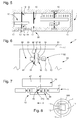
- the invention relates to a watch mechanism structure 1 for receiving and guiding at least one pivoting mobile device 10, comprising at least one shaft 47 comprising pivoting guides:
- a mobile device 10 can also comprise only guides end, without any tree part along its entire length, the present description however uses the name "shaft 47" for the sake of simplicity, to designate the guides or pivots that includes the pivoting mobile 10.
- this structure 1 comprises at least one unmountable integral structure 11, which comprises at least one unbreakable monobloc frame 17 which comprises pivoting housings 12 aligned two by two for the reception of pivots of a shaft 47 from to least one such pivoting mobile 10.
- Each said pivoting housing 12 is an open housing constituted by a half-bearing or a dihedron, and has at one end an abutment bearing surface 120 in the alignment direction A.
- this unbreakable integral structure 11 comprises at least one unbreakable integral frame 17, which comprises, forming in particular an upper bearing 44 and a lower bearing 45, pivoting housings 12 aligned in pairs. for receiving pivots of at least one such pivoting mobile 10.
- the structure 1 further comprises at least one cover 18, which is arranged to cooperate with this at least one frame 17 for, in the closed position of this at least one cover 18 on this at least one frame 17, to enclose at a minimum clearance each such shaft 47 of each such pivoting mobile 10 that includes the structure 1.
- at least one cover 18 is arranged to cooperate with this at least one frame 17 for, in the closed position of this at least one cover 18 on this at least one frame 17, to enclose at a minimum clearance each such shaft 47 of each such pivoting mobile 10 that includes the structure 1.
- At least one such cover 18 is made integrally with such a frame 17, to which it is connected by a flexible attachment, and on which it is folded after insertion of the pivoting mobile or 10, or the like.
- the cover 18 is irreversibly fixed to the frame 17, by welding, soldering, laser welding, bonding, riveting, or otherwise, to constitute together the integral structure 11 unmountable, after the prisoner mounting pivoting mobile 10 in position in pivoting housing 12.
- the structure 1 incorporates a plate and / or at least one bridge constituting the frame 17 or being attached thereto (e) indemountably.
- the frame 17 may also be independent of the plate and the bridge, and be fixed on one or the other of the two, or both at the same time.
- the frame 17 is a closed frame, and in particular a closed rectangular frame.
- the structure 1 comprises flexible means 18A of play catching, to lock without play each such shaft 47 of each such movable mobile 10 that includes the cassette 1.
- the figure 4 illustrates an exemplary embodiment of the cover 18 with elastic lips 18A performing this play catching.
- These flexible play catching means can equip both the frame 17 and the cover 18.
- At least one pivoting housing 12 is a dihedron 460.
- the figure 7 illustrates a particular case where the structure 1 comprises at least one pivoting housing 12 which has a revolution range 46 for the radial retention of such a shaft 47 of pivoting mobile 10, and the abutment bearing surface 120 is a range frontal 49 for the axial limitation of the end of such a shaft 47, this range of revolution 46 and / or this front span 49 being carried / s by at least one resilient shock absorber 48.
- the revolution range 46 and the front span 49 are carried together by at least one elastic shock absorber 48.
- revolution range 46 or the front span 49 is carried by a shock absorber of its own.
- revolution range 46 and the front span 49 are carried separately by a shock absorber, which may be common with two bearing surfaces, or multiple, each scope being carried by a shock absorber which it's clean.
- revolution range 46 and the front span 49 are carried together by an elastic shock absorber 48.
- this elastic shock absorber 48 is integral with the integral structure 11, and in particular with the frame 17.
- this range of revolution 46 or / and this front span 49 is integral with the frame 17.
- this elastic shock absorber 48, this range of revolution 46 and / or this front span 49 are, together, integral with the unbreakable integral structure 11, and in particular with the frame 17.
- the unbreakable integral structure 11 is made of silicon, and the intrinsic elastic return means it comprises, if it is the case, are prestressed in an oxidized state of silicon.
- the frame 17 is made of silicon, and the intrinsic elastic return means it comprises are prestressed in an oxidized state of silicon.
- the pivots 44, 45 may be constituted by conventional pivots or by flexible guides.
- structures 1 according to the invention comprising unbreakable monobloc components 17 makes it possible, again, to optimize the pivoting of the different mobiles, and, as required, to ensure their parallelism, or conversely to move at least one end of a mobile shaft to modify a setting micrometrically.
- the action on the pivoting housing allows, in particular, to adjust the distance between mobile to adjust the penetration of the teeth and / or lifted. Adjustment of the center distance can be achieved monolithically with the deck or bridge. This principle of adjustment of the distances is valid for all the distances in a movement.
- At least one said pivoting housing 12 is integral with an arm or bearing carrier13 connected to the frame 17 by elastic return means 14 and 83, respectively.
- pivoting housings 12 have an invariable position with respect to the at least one unmountable integral structure 11.
- At least one pivoting housing 12 is suspended, in particular so as to be able to absorb the energy of a shock, and to return to the service position.
- the figure 5 thus illustrates elastic return means 14 of sufficient rigidity to ensure, at rest, the precise positioning of the pivoting housing 12, and designed to absorb any shocks and then return the axis in its position.
- at least one pivoting member 10 is pivoted, at least at one of its ends, in a pivot 45 constituting the housing 460, which is housed in an arm or bearing carrier 13.
- This arm or bearing holder 13 is connected to the frame 17 by these integrated elastic return means 14, which are preferably monoblock with both the frame 17, and with the respective arm or bearing holder13.
- the elastic return means 14 allow a setting range, preferably they are associated with means for locking in position after adjustment, the present description gives an example in the particular case of the figure 6 .
- these position locking means are also made integrally with the frame 17, and with the arm or bearer bearing 13 respectively.
- the structure 1 preferably comprises, at the level of the frame 17, a mechanism adjustable in position 80, as visible on the figure 6 .
- the figure 6 thus illustrates a particular arrangement, wherein an arm or bearing carrier 13, is mounted integral with a component adjustable in position, and lock in position once set.
- the unbreakable integral structure 11 comprises a position adjustment mechanism 80 of an adjustable component in position 82 comprising an arm or bearing carrier 13 connected to the frame 17 by elastic return means 83.
- This mechanism 80 comprises a rigid structure 81, preferably constituted by the frame 17.
- This rigid structure 81 carries, via at least one elastic blade 83, this adjustable component in position 82, which here carries an arm or bearing-bearing13, and which itself comprises indexing means 84 arranged to cooperate with complementary indexing means 91 that includes a setting mechanism 90.
- These complementary indexing means 91 are mounted disengageable indexing means 84.
- This locking mechanism 94 is elastically fixed to the structure 81 by at least one flexible element 9 6, and is itself subject to the action of a locking mechanism 98 which allows it to occupy, or a disengaged position in which the adjustment mechanism 90 is free, or an engaged position in which the mechanism blocker 94 obstructs the adjustment mechanism 90.
- This locking mechanism comprises at least one flexible element 98 which is jumpered and resiliently fastened to the structure 81, this at least one element flexible 98 here comprises a spout 99 which cooperates with a spout 97 of the blocker 94 to keep the blocker spread during adjustment in position, or with a complementary stop surface 95 of the blocker 94 in the safety of the blocker when the adjustment in position is carried out .
- the figure 6 illustrates such a mechanism with a comb 91 immobilizing an index 84 located at the end of a flexible blade 83, the comb 91 being pressed on this index 84 by a locking spring blade 96 belonging to the blocker 94, itself immobilized by a locking pin 99 mounted on at least one flexible blade 98, this finger 99 cooperating with a stop surface 97 of the blade 96.
- this combined mechanism of adjustment, locking and locking illustrated here for a particular application of adjustment of a bearing position, for example to perform a micrometric correction on the operation of a regulating mechanism, is applicable to a wide variety of applications: positioning a bearing, a stop, or other.
- the structure 1, or / and the frame 17, is made of silicon.
- the housing of pivoting housing 460 are defined, for example, by anisotropic etchings (KOH) in a silicon substrate.
- KOH anisotropic etchings
- a version with an assembly of stones or shockproof is also possible.
- the big advantage is the very precise positioning of the pivoting housing (center distance, verticality). It is noted that the installation of the cover 18 does not disturb the positioning of the various shafts.
- FIGS 9 to 15 illustrate particular, non-limiting variants of application of the invention. It is understood that, if a preferential application consists in positioning pivoting elements, it is also possible to envisage fixing non-pivoting elements, such as a peg, or a leaf-spring, or other.
- the figure 9 thus shows an escapement mechanism with a balance-spring, the pin 19 for holding the spiral 190 is integral with the one-piece frame 17 specific to the invention.
- the frame 17 forms a single-piece component that can not be dismantled with at least one shockproof bearing for receiving a pivot of a component of the mechanism incorporated in the structure 1, in particular an escapement mechanism. .
- the invention allows two shockproof in one piece to form for example a bridge (or cassette).
- a bridge or cassette
- the invention also covers a monolithic bridge. The advantages are a very precise positioning, and the absence of assembly.
- the shockproof may thus be partially or completely made in the frame 17, especially in a silicon embodiment or the like: the spring 14 of the shockproof can be made in common with the frame 17.
- One of the two (or both) stones 13 can be carried out in common with the plate. Pivoting is then done directly in the silicon.
- the pivoting housings 12 can be made directly in the silicon with surface coatings of the DLC or other type. So there is no more stone, and the rotation points are positioned very precisely.
- FIGS. 10 to 12 illustrate such a one-piece frame 17 bearing two bearings 13 mounted on shockproof also monobloc with this frame 17.
- the figure 16 illustrates a cassette made of silicon or the like, with several levels. It carries an oscillator which comprises an escape wheel 901, the axis of which is adjusted in position by the systems 902a and 902b, a flexible guide anchor 903, and a balance-balance assembly, the 908 of which keeps the hairspring 905 is held at a bridge 907a, with which this stud 908 is preferably monoblock; the pivots of the balance 904 are held by suspended shockproof, which are each one-piece with an element of the platen cassette 907b on the one hand, and another element of the same bridge cassette 907a on the other hand.
- the figure 11 shows an elaboration of this frame 17 in a structure of silicon type, comprising two levels, a first level 17H said “handle” and a second level 17D called “device", not detailed here because well known to micromaterials specialists, with a different distribution of counter-pivot functions 131 on the layer “handle” and bore 130 on the “device” layer, and with elastic elements 14 belonging to one or the other of these two layers.
- the figure 12 illustrates a simplified variant, and the like.
- the invention makes it possible, again, to produce a structure similar to a shockproof with springs, and a barrel which serves as a stop; such a structure is advantageously in two levels.
- the figure 13 represents a monobloc frame 17, similar to the structure of the figure 1 , and also comprising two such levels 17H “handle” and 17D “device", with a dihedral half-pad 460 housed in the layer 17D "device".
- This first level 17D "device” has an opening 15 in the upper part, delimited by the flush surface of the second level 17H "handle”.
- the frame 17 comprises a bearing surface 21, arranged to cooperate with a complementary bearing face 210 of an antagonistic component, or a cover 18, as can also be seen on the Figures 1 to 4 .
- this antagonist component is symmetrical, or even identical, to the frame 17 as illustrated.
- the figure 14 represents a variant arranged to control an interaxial variation E between two bores 51 and 52 carried by such a monobloc frame 17.
- FIG 15 illustrates another variant control preload of a bistable blade 53 carried by such a monobloc frame 17 at its end points 54 and 55.
- the end 54 is carried by an arm 13A connected to the frame 17 by elastic return means 83, and carrying the indexing means 84.
- Yet another variant relates to a pivoting for a sprung balance, where the shock completely includes, or just with a stone 13 with spring hole 14, the counter-pivot stone being reported thereafter, and an anchor cooperating with the balance and being flexible guide in the same bridge.
- This variant is also feasible in two levels “handle” and “device”.
- the structure 1 comprises breakable elements, intended to facilitate assembly in an upper assembly, it is sufficient to then break these breakable elements to give one or more degrees of freedom to some of its constituents.
- the structure 1 is made of micro-machinable material, or silicon, or oxidized silicon, and any intrinsic elastic return means it comprises are prestressed in a state oxidized silicon.
- Other materials according to MEMS or "LIGA" technologies can be implemented. Quartz, DLC, at least partially amorphous materials, metallic glasses, can, and not exclusively, be used for these applications.
- a particular structure of the structure 1 can compensate for the effects of the expansion of these structural elements, or components of the assembled mechanism in combination with it. It is for example possible to make the silicon board, then to oxidize it, in order to work coherently.
- the invention also relates to a mechanical clockwork movement 100 comprising at least one such structure 1.
- the invention also relates to a method for producing such a watch mechanism structure 1 for receiving and guiding at least one pivoting mobile 10.
- the unmountable monoblock structure 11 is intrinsic resilient return monoblock with it, or to maintain without play at least one shaft 47 of at least one pivoting mobile 10, and / or to constitute at least one elastic shock absorber 48, and / or to allow a setting of position of an arm or bearing holder13.
- the unbreakable monobloc structure 11 is made of silicon, and said intrinsic elastic return means is prestressed in an oxidized state of said silicon.
- pivoting housings 12 are made directly in the silicon with DLC-type surface coatings.
- the unbreakable integral structure 11 is produced with at least one unbreakable monobloc frame 17 comprising pivoting housings 12 aligned two by two for the reception of pivots of at least one said pivoting mobile 10, and these housings are made of pivoting 12 by anisotropic etchings in a silicon substrate.
- the unbreakable integral structure 11 is formed with the frame 17 and a cover 18 trapping the pivoting members 10 together in position in the pivoting housings 12, and fastened together so as to irreversible the frame 17 and the cover 18 by welding or soldering or gluing or riveting or laser welding to form a unit integral unbreakable.
- the high precision provided by the invention makes it possible to thin the components, and therefore the movement.
- the invention is therefore particularly useful for performing ultra-thin movements.
Landscapes
- Physics & Mathematics (AREA)
- General Physics & Mathematics (AREA)
- Micromachines (AREA)
- Pivots And Pivotal Connections (AREA)
- Details Of Measuring And Other Instruments (AREA)
- Electric Clocks (AREA)
Priority Applications (1)
| Application Number | Priority Date | Filing Date | Title |
|---|---|---|---|
| EP14158656.0A EP2790070B1 (de) | 2013-03-19 | 2014-03-10 | Struktur für Uhrwerksmechanismus |
Applications Claiming Priority (2)
| Application Number | Priority Date | Filing Date | Title |
|---|---|---|---|
| EP13160027.2A EP2781971B1 (de) | 2013-03-19 | 2013-03-19 | Struktur für Uhrwerksmechanismus |
| EP14158656.0A EP2790070B1 (de) | 2013-03-19 | 2014-03-10 | Struktur für Uhrwerksmechanismus |
Publications (3)
| Publication Number | Publication Date |
|---|---|
| EP2790070A2 true EP2790070A2 (de) | 2014-10-15 |
| EP2790070A3 EP2790070A3 (de) | 2016-06-22 |
| EP2790070B1 EP2790070B1 (de) | 2017-11-15 |
Family
ID=47997064
Family Applications (2)
| Application Number | Title | Priority Date | Filing Date |
|---|---|---|---|
| EP13160027.2A Active EP2781971B1 (de) | 2013-03-19 | 2013-03-19 | Struktur für Uhrwerksmechanismus |
| EP14158656.0A Active EP2790070B1 (de) | 2013-03-19 | 2014-03-10 | Struktur für Uhrwerksmechanismus |
Family Applications Before (1)
| Application Number | Title | Priority Date | Filing Date |
|---|---|---|---|
| EP13160027.2A Active EP2781971B1 (de) | 2013-03-19 | 2013-03-19 | Struktur für Uhrwerksmechanismus |
Country Status (7)
| Country | Link |
|---|---|
| US (1) | US9235191B2 (de) |
| EP (2) | EP2781971B1 (de) |
| JP (1) | JP5798652B2 (de) |
| KR (1) | KR101545443B1 (de) |
| CN (1) | CN104062888B (de) |
| CH (1) | CH707813A2 (de) |
| TW (1) | TWI610154B (de) |
Families Citing this family (4)
| Publication number | Priority date | Publication date | Assignee | Title |
|---|---|---|---|---|
| EP3382468B1 (de) * | 2017-03-30 | 2020-01-15 | The Swatch Group Research and Development Ltd | Uhrwerk mit verlängerung der gangreserve |
| CH716957A2 (fr) * | 2019-12-16 | 2021-06-30 | Eta Sa Mft Horlogere Suisse | Dispositif de guidage pour afficheur d'horlogerie. |
| EP3929667B1 (de) * | 2020-06-26 | 2025-09-03 | ETA SA Manufacture Horlogère Suisse | Mobiles drehsystem eines uhrwerks |
| CN112718072B (zh) * | 2020-12-09 | 2022-04-19 | 安徽华铂再生资源科技有限公司 | 一种废铅蓄电池回收用破碎设备及其工作方法 |
Citations (7)
| Publication number | Priority date | Publication date | Assignee | Title |
|---|---|---|---|---|
| NL11224C (de) | ||||
| US580046A (en) | 1897-04-06 | Watc h - plate | ||
| CH488169A (fr) | 1968-02-26 | 1970-03-31 | Lapanouse Montres Rego S A R | Dispositif de pivotement pour aiguille de boussole |
| US3582162A (en) | 1969-11-03 | 1971-06-01 | Max Baermann | Temperature compensated permanent magnet bearing |
| DE2218663A1 (de) | 1972-04-18 | 1973-10-25 | Mueller Schlenker Fa | Lageranordnung fuer unruhen mit senkrechter welle |
| JPS5149063A (de) | 1974-10-24 | 1976-04-27 | Suwa Seikosha Kk | |
| FR2807160A1 (fr) | 2000-03-30 | 2001-10-05 | Denso Corp | Agencement d'arbre d'un appareil de mesure indicateur |
Family Cites Families (21)
| Publication number | Priority date | Publication date | Assignee | Title |
|---|---|---|---|---|
| CH427657A (fr) * | 1961-11-29 | 1966-09-15 | Parechoc Sa | Palier amortisseur de chocs pour mobile d'horlogerie |
| US3306028A (en) * | 1966-01-04 | 1967-02-28 | Citizen Watch Co Ltd | Shock-proof device for watches |
| JPS513002Y1 (de) * | 1970-12-28 | 1976-01-28 | ||
| CH1052871A4 (de) * | 1971-07-15 | 1974-09-13 | ||
| CH495673A4 (fr) * | 1973-04-06 | 1976-10-29 | Seitz Sa | Dispositif de pivotement de l'ace d'un mobile d'horlogerie |
| JPS5149063U (de) * | 1974-10-11 | 1976-04-13 | ||
| JPS5239167U (de) * | 1975-09-10 | 1977-03-19 | ||
| JPS6288983U (de) * | 1985-11-25 | 1987-06-06 | ||
| US5369627A (en) * | 1987-07-21 | 1994-11-29 | Seiko Epson Corporation | Improvements in bearing and frame structure of a timepiece |
| US5416752A (en) * | 1987-07-21 | 1995-05-16 | Seiko Epson Corporation | Timepiece |
| AU6406399A (en) | 1998-09-30 | 2000-04-17 | Bionx Implants Oy | Chute for endosteal ligament fixation |
| US6755566B2 (en) * | 2001-02-15 | 2004-06-29 | Konrad Damasko | Clockwork |
| DE602005025585D1 (de) * | 2005-02-23 | 2011-02-10 | Eta Sa Mft Horlogere Suisse | Stoßdämpfende Uhrenlagerung |
| DE602005006731D1 (de) * | 2005-03-23 | 2008-06-26 | Rolex Sa | Stoßdämpfende Lagerung für Uhren |
| JP4992319B2 (ja) * | 2006-07-10 | 2012-08-08 | セイコーエプソン株式会社 | 時計 |
| EP1986059A1 (de) * | 2007-04-26 | 2008-10-29 | ETA SA Manufacture Horlogère Suisse | Schwenkenvorrichtung einer Welle in einer Uhr |
| EP2060957A1 (de) | 2007-11-16 | 2009-05-20 | ETA SA Manufacture Horlogère Suisse | Motorelement mit federn für uhrwerk |
| EP2585882B1 (de) * | 2010-06-22 | 2021-02-24 | The Swatch Group Research and Development Ltd. | Stossdämpfungssystem für eine uhr |
| EP2410386B1 (de) | 2010-07-19 | 2018-10-03 | Nivarox-FAR S.A. | Unruh mit Trägheitsregulierung mit Einsatzteil |
| EP2605087B1 (de) | 2011-12-13 | 2017-07-26 | ETA SA Manufacture Horlogère Suisse | Uhrmoduleinheit mit funktionellen Modulen |
| EP2787399B1 (de) | 2011-12-13 | 2015-07-29 | ETA SA Manufacture Horlogère Suisse | Mechanisches Uhrwerk einer modularen Uhr mit funktionellen Modulen |
-
2013
- 2013-03-19 CH CH00630/13A patent/CH707813A2/fr not_active Application Discontinuation
- 2013-03-19 EP EP13160027.2A patent/EP2781971B1/de active Active
-
2014
- 2014-02-13 TW TW103104730A patent/TWI610154B/zh active
- 2014-03-10 EP EP14158656.0A patent/EP2790070B1/de active Active
- 2014-03-11 US US14/204,160 patent/US9235191B2/en active Active
- 2014-03-18 JP JP2014054685A patent/JP5798652B2/ja active Active
- 2014-03-18 KR KR1020140031461A patent/KR101545443B1/ko active Active
- 2014-03-19 CN CN201410102917.2A patent/CN104062888B/zh active Active
Patent Citations (7)
| Publication number | Priority date | Publication date | Assignee | Title |
|---|---|---|---|---|
| NL11224C (de) | ||||
| US580046A (en) | 1897-04-06 | Watc h - plate | ||
| CH488169A (fr) | 1968-02-26 | 1970-03-31 | Lapanouse Montres Rego S A R | Dispositif de pivotement pour aiguille de boussole |
| US3582162A (en) | 1969-11-03 | 1971-06-01 | Max Baermann | Temperature compensated permanent magnet bearing |
| DE2218663A1 (de) | 1972-04-18 | 1973-10-25 | Mueller Schlenker Fa | Lageranordnung fuer unruhen mit senkrechter welle |
| JPS5149063A (de) | 1974-10-24 | 1976-04-27 | Suwa Seikosha Kk | |
| FR2807160A1 (fr) | 2000-03-30 | 2001-10-05 | Denso Corp | Agencement d'arbre d'un appareil de mesure indicateur |
Also Published As
| Publication number | Publication date |
|---|---|
| TWI610154B (zh) | 2018-01-01 |
| JP5798652B2 (ja) | 2015-10-21 |
| EP2790070A3 (de) | 2016-06-22 |
| EP2790070B1 (de) | 2017-11-15 |
| US20140286139A1 (en) | 2014-09-25 |
| EP2781971B1 (de) | 2017-11-08 |
| KR20140114782A (ko) | 2014-09-29 |
| CN104062888B (zh) | 2017-03-01 |
| CH707813A2 (fr) | 2014-09-30 |
| US9235191B2 (en) | 2016-01-12 |
| JP2014182145A (ja) | 2014-09-29 |
| KR101545443B1 (ko) | 2015-08-18 |
| EP2781971A1 (de) | 2014-09-24 |
| HK1202654A1 (en) | 2015-10-02 |
| CN104062888A (zh) | 2014-09-24 |
| TW201500868A (zh) | 2015-01-01 |
Similar Documents
| Publication | Publication Date | Title |
|---|---|---|
| EP2781967B1 (de) | Spiralfeder einer Uhr | |
| EP3545363B1 (de) | Sich drehender resonator mit einer flexiblen führung, der von einer freien ankerhemmung gehalten wird | |
| EP2781970B1 (de) | Spiralfederregulierungsmechanismus einer Uhr | |
| EP2790066B1 (de) | Kassette für Uhrwerksmechanismus | |
| EP2781969B1 (de) | Unzerlegbare Monoblock-Komponente einer Uhr | |
| EP3172626B1 (de) | Drehzapfen mit einem blatt | |
| EP2799937B1 (de) | Dämpfungskörper eines Unruh-Oszillators einer Uhr | |
| EP2976684B1 (de) | Zapfen für uhrwerksmechanismus | |
| EP2690507A1 (de) | Spiralfeder einer Uhr | |
| EP2790070B1 (de) | Struktur für Uhrwerksmechanismus | |
| EP2887151B1 (de) | Schwungelement für Uhrwerk | |
| EP2948820B1 (de) | Führungsvorrichtung für uhrwerkswelle | |
| EP2466397B1 (de) | Drehteil einer Uhr mit peripherem Antrieb | |
| EP2976682B1 (de) | Anker für uhrhemmungsmechanismus | |
| CH705075B1 (fr) | Dispositif antichoc réglable d'horlogerie et procédé de réglage. | |
| CH707810A2 (fr) | Mécanisme de blocage intermittent, tel une ancre, pour mécanisme d'échappement d'horlogerie. | |
| CH704239A2 (fr) | Mobile d'horlogerie à guidage périphérique. | |
| EP2653938A1 (de) | Unruh für Uhrwerk | |
| CH713837B1 (fr) | Dispositif de régulation sur la base d'un oscillateur harmonique isotrope pour pièce d'horlogerie. | |
| CH706763A2 (fr) | Ensemble horloger comportant un spiral d'horlogerie. |
Legal Events
| Date | Code | Title | Description |
|---|---|---|---|
| PUAI | Public reference made under article 153(3) epc to a published international application that has entered the european phase |
Free format text: ORIGINAL CODE: 0009012 |
|
| 17P | Request for examination filed |
Effective date: 20140310 |
|
| AK | Designated contracting states |
Kind code of ref document: A2 Designated state(s): AL AT BE BG CH CY CZ DE DK EE ES FI FR GB GR HR HU IE IS IT LI LT LU LV MC MK MT NL NO PL PT RO RS SE SI SK SM TR |
|
| AX | Request for extension of the european patent |
Extension state: BA ME |
|
| PUAL | Search report despatched |
Free format text: ORIGINAL CODE: 0009013 |
|
| AK | Designated contracting states |
Kind code of ref document: A3 Designated state(s): AL AT BE BG CH CY CZ DE DK EE ES FI FR GB GR HR HU IE IS IT LI LT LU LV MC MK MT NL NO PL PT RO RS SE SI SK SM TR |
|
| AX | Request for extension of the european patent |
Extension state: BA ME |
|
| RIC1 | Information provided on ipc code assigned before grant |
Ipc: G04B 29/00 20060101AFI20160519BHEP Ipc: G04B 31/00 20060101ALI20160519BHEP |
|
| R17P | Request for examination filed (corrected) |
Effective date: 20161222 |
|
| RBV | Designated contracting states (corrected) |
Designated state(s): AL AT BE BG CH CY CZ DE DK EE ES FI FR GB GR HR HU IE IS IT LI LT LU LV MC MK MT NL NO PL PT RO RS SE SI SK SM TR |
|
| GRAP | Despatch of communication of intention to grant a patent |
Free format text: ORIGINAL CODE: EPIDOSNIGR1 |
|
| INTG | Intention to grant announced |
Effective date: 20170704 |
|
| GRAS | Grant fee paid |
Free format text: ORIGINAL CODE: EPIDOSNIGR3 |
|
| GRAA | (expected) grant |
Free format text: ORIGINAL CODE: 0009210 |
|
| AK | Designated contracting states |
Kind code of ref document: B1 Designated state(s): AL AT BE BG CH CY CZ DE DK EE ES FI FR GB GR HR HU IE IS IT LI LT LU LV MC MK MT NL NO PL PT RO RS SE SI SK SM TR |
|
| REG | Reference to a national code |
Ref country code: CH Ref legal event code: EP Ref country code: GB Ref legal event code: FG4D Free format text: NOT ENGLISH Ref country code: CH Ref legal event code: NV Representative=s name: ICB INGENIEURS CONSEILS EN BREVETS SA, CH Ref country code: AT Ref legal event code: REF Ref document number: 946867 Country of ref document: AT Kind code of ref document: T Effective date: 20171115 |
|
| REG | Reference to a national code |
Ref country code: IE Ref legal event code: FG4D Free format text: LANGUAGE OF EP DOCUMENT: FRENCH |
|
| REG | Reference to a national code |
Ref country code: DE Ref legal event code: R096 Ref document number: 602014017116 Country of ref document: DE |
|
| REG | Reference to a national code |
Ref country code: FR Ref legal event code: PLFP Year of fee payment: 5 |
|
| REG | Reference to a national code |
Ref country code: NL Ref legal event code: MP Effective date: 20171115 |
|
| REG | Reference to a national code |
Ref country code: LT Ref legal event code: MG4D |
|
| REG | Reference to a national code |
Ref country code: AT Ref legal event code: MK05 Ref document number: 946867 Country of ref document: AT Kind code of ref document: T Effective date: 20171115 |
|
| PG25 | Lapsed in a contracting state [announced via postgrant information from national office to epo] |
Ref country code: NO Free format text: LAPSE BECAUSE OF FAILURE TO SUBMIT A TRANSLATION OF THE DESCRIPTION OR TO PAY THE FEE WITHIN THE PRESCRIBED TIME-LIMIT Effective date: 20180215 Ref country code: NL Free format text: LAPSE BECAUSE OF FAILURE TO SUBMIT A TRANSLATION OF THE DESCRIPTION OR TO PAY THE FEE WITHIN THE PRESCRIBED TIME-LIMIT Effective date: 20171115 Ref country code: FI Free format text: LAPSE BECAUSE OF FAILURE TO SUBMIT A TRANSLATION OF THE DESCRIPTION OR TO PAY THE FEE WITHIN THE PRESCRIBED TIME-LIMIT Effective date: 20171115 Ref country code: LT Free format text: LAPSE BECAUSE OF FAILURE TO SUBMIT A TRANSLATION OF THE DESCRIPTION OR TO PAY THE FEE WITHIN THE PRESCRIBED TIME-LIMIT Effective date: 20171115 Ref country code: SE Free format text: LAPSE BECAUSE OF FAILURE TO SUBMIT A TRANSLATION OF THE DESCRIPTION OR TO PAY THE FEE WITHIN THE PRESCRIBED TIME-LIMIT Effective date: 20171115 Ref country code: ES Free format text: LAPSE BECAUSE OF FAILURE TO SUBMIT A TRANSLATION OF THE DESCRIPTION OR TO PAY THE FEE WITHIN THE PRESCRIBED TIME-LIMIT Effective date: 20171115 |
|
| PG25 | Lapsed in a contracting state [announced via postgrant information from national office to epo] |
Ref country code: HR Free format text: LAPSE BECAUSE OF FAILURE TO SUBMIT A TRANSLATION OF THE DESCRIPTION OR TO PAY THE FEE WITHIN THE PRESCRIBED TIME-LIMIT Effective date: 20171115 Ref country code: AT Free format text: LAPSE BECAUSE OF FAILURE TO SUBMIT A TRANSLATION OF THE DESCRIPTION OR TO PAY THE FEE WITHIN THE PRESCRIBED TIME-LIMIT Effective date: 20171115 Ref country code: RS Free format text: LAPSE BECAUSE OF FAILURE TO SUBMIT A TRANSLATION OF THE DESCRIPTION OR TO PAY THE FEE WITHIN THE PRESCRIBED TIME-LIMIT Effective date: 20171115 Ref country code: LV Free format text: LAPSE BECAUSE OF FAILURE TO SUBMIT A TRANSLATION OF THE DESCRIPTION OR TO PAY THE FEE WITHIN THE PRESCRIBED TIME-LIMIT Effective date: 20171115 Ref country code: GR Free format text: LAPSE BECAUSE OF FAILURE TO SUBMIT A TRANSLATION OF THE DESCRIPTION OR TO PAY THE FEE WITHIN THE PRESCRIBED TIME-LIMIT Effective date: 20180216 Ref country code: BG Free format text: LAPSE BECAUSE OF FAILURE TO SUBMIT A TRANSLATION OF THE DESCRIPTION OR TO PAY THE FEE WITHIN THE PRESCRIBED TIME-LIMIT Effective date: 20180215 |
|
| PG25 | Lapsed in a contracting state [announced via postgrant information from national office to epo] |
Ref country code: CZ Free format text: LAPSE BECAUSE OF FAILURE TO SUBMIT A TRANSLATION OF THE DESCRIPTION OR TO PAY THE FEE WITHIN THE PRESCRIBED TIME-LIMIT Effective date: 20171115 Ref country code: CY Free format text: LAPSE BECAUSE OF FAILURE TO SUBMIT A TRANSLATION OF THE DESCRIPTION OR TO PAY THE FEE WITHIN THE PRESCRIBED TIME-LIMIT Effective date: 20171115 Ref country code: EE Free format text: LAPSE BECAUSE OF FAILURE TO SUBMIT A TRANSLATION OF THE DESCRIPTION OR TO PAY THE FEE WITHIN THE PRESCRIBED TIME-LIMIT Effective date: 20171115 Ref country code: DK Free format text: LAPSE BECAUSE OF FAILURE TO SUBMIT A TRANSLATION OF THE DESCRIPTION OR TO PAY THE FEE WITHIN THE PRESCRIBED TIME-LIMIT Effective date: 20171115 Ref country code: SK Free format text: LAPSE BECAUSE OF FAILURE TO SUBMIT A TRANSLATION OF THE DESCRIPTION OR TO PAY THE FEE WITHIN THE PRESCRIBED TIME-LIMIT Effective date: 20171115 |
|
| REG | Reference to a national code |
Ref country code: DE Ref legal event code: R097 Ref document number: 602014017116 Country of ref document: DE |
|
| PG25 | Lapsed in a contracting state [announced via postgrant information from national office to epo] |
Ref country code: IT Free format text: LAPSE BECAUSE OF FAILURE TO SUBMIT A TRANSLATION OF THE DESCRIPTION OR TO PAY THE FEE WITHIN THE PRESCRIBED TIME-LIMIT Effective date: 20171115 Ref country code: RO Free format text: LAPSE BECAUSE OF FAILURE TO SUBMIT A TRANSLATION OF THE DESCRIPTION OR TO PAY THE FEE WITHIN THE PRESCRIBED TIME-LIMIT Effective date: 20171115 Ref country code: PL Free format text: LAPSE BECAUSE OF FAILURE TO SUBMIT A TRANSLATION OF THE DESCRIPTION OR TO PAY THE FEE WITHIN THE PRESCRIBED TIME-LIMIT Effective date: 20171115 Ref country code: SM Free format text: LAPSE BECAUSE OF FAILURE TO SUBMIT A TRANSLATION OF THE DESCRIPTION OR TO PAY THE FEE WITHIN THE PRESCRIBED TIME-LIMIT Effective date: 20171115 |
|
| PLBE | No opposition filed within time limit |
Free format text: ORIGINAL CODE: 0009261 |
|
| STAA | Information on the status of an ep patent application or granted ep patent |
Free format text: STATUS: NO OPPOSITION FILED WITHIN TIME LIMIT |
|
| PG25 | Lapsed in a contracting state [announced via postgrant information from national office to epo] |
Ref country code: MT Free format text: LAPSE BECAUSE OF FAILURE TO SUBMIT A TRANSLATION OF THE DESCRIPTION OR TO PAY THE FEE WITHIN THE PRESCRIBED TIME-LIMIT Effective date: 20171115 |
|
| 26N | No opposition filed |
Effective date: 20180817 |
|
| PG25 | Lapsed in a contracting state [announced via postgrant information from national office to epo] |
Ref country code: SI Free format text: LAPSE BECAUSE OF FAILURE TO SUBMIT A TRANSLATION OF THE DESCRIPTION OR TO PAY THE FEE WITHIN THE PRESCRIBED TIME-LIMIT Effective date: 20171115 Ref country code: MC Free format text: LAPSE BECAUSE OF FAILURE TO SUBMIT A TRANSLATION OF THE DESCRIPTION OR TO PAY THE FEE WITHIN THE PRESCRIBED TIME-LIMIT Effective date: 20171115 |
|
| REG | Reference to a national code |
Ref country code: BE Ref legal event code: MM Effective date: 20180331 |
|
| REG | Reference to a national code |
Ref country code: IE Ref legal event code: MM4A |
|
| PG25 | Lapsed in a contracting state [announced via postgrant information from national office to epo] |
Ref country code: LU Free format text: LAPSE BECAUSE OF NON-PAYMENT OF DUE FEES Effective date: 20180310 |
|
| PG25 | Lapsed in a contracting state [announced via postgrant information from national office to epo] |
Ref country code: IE Free format text: LAPSE BECAUSE OF NON-PAYMENT OF DUE FEES Effective date: 20180310 |
|
| PG25 | Lapsed in a contracting state [announced via postgrant information from national office to epo] |
Ref country code: BE Free format text: LAPSE BECAUSE OF NON-PAYMENT OF DUE FEES Effective date: 20180331 |
|
| PG25 | Lapsed in a contracting state [announced via postgrant information from national office to epo] |
Ref country code: TR Free format text: LAPSE BECAUSE OF FAILURE TO SUBMIT A TRANSLATION OF THE DESCRIPTION OR TO PAY THE FEE WITHIN THE PRESCRIBED TIME-LIMIT Effective date: 20171115 |
|
| PG25 | Lapsed in a contracting state [announced via postgrant information from national office to epo] |
Ref country code: PT Free format text: LAPSE BECAUSE OF FAILURE TO SUBMIT A TRANSLATION OF THE DESCRIPTION OR TO PAY THE FEE WITHIN THE PRESCRIBED TIME-LIMIT Effective date: 20171115 Ref country code: HU Free format text: LAPSE BECAUSE OF FAILURE TO SUBMIT A TRANSLATION OF THE DESCRIPTION OR TO PAY THE FEE WITHIN THE PRESCRIBED TIME-LIMIT; INVALID AB INITIO Effective date: 20140310 |
|
| PG25 | Lapsed in a contracting state [announced via postgrant information from national office to epo] |
Ref country code: MK Free format text: LAPSE BECAUSE OF NON-PAYMENT OF DUE FEES Effective date: 20171115 |
|
| PG25 | Lapsed in a contracting state [announced via postgrant information from national office to epo] |
Ref country code: AL Free format text: LAPSE BECAUSE OF FAILURE TO SUBMIT A TRANSLATION OF THE DESCRIPTION OR TO PAY THE FEE WITHIN THE PRESCRIBED TIME-LIMIT Effective date: 20171115 Ref country code: IS Free format text: LAPSE BECAUSE OF FAILURE TO SUBMIT A TRANSLATION OF THE DESCRIPTION OR TO PAY THE FEE WITHIN THE PRESCRIBED TIME-LIMIT Effective date: 20180315 |
|
| P01 | Opt-out of the competence of the unified patent court (upc) registered |
Effective date: 20230611 |
|
| PGFP | Annual fee paid to national office [announced via postgrant information from national office to epo] |
Ref country code: CH Payment date: 20250401 Year of fee payment: 12 |
|
| REG | Reference to a national code |
Ref country code: CH Ref legal event code: U11 Free format text: ST27 STATUS EVENT CODE: U-0-0-U10-U11 (AS PROVIDED BY THE NATIONAL OFFICE) Effective date: 20260401 |
|
| PGFP | Annual fee paid to national office [announced via postgrant information from national office to epo] |
Ref country code: GB Payment date: 20260220 Year of fee payment: 13 |
|
| PGFP | Annual fee paid to national office [announced via postgrant information from national office to epo] |
Ref country code: DE Payment date: 20260219 Year of fee payment: 13 |
|
| PGFP | Annual fee paid to national office [announced via postgrant information from national office to epo] |
Ref country code: FR Payment date: 20260219 Year of fee payment: 13 |