EP2790084A2 - Dispositif à charnière - Google Patents
Dispositif à charnière Download PDFInfo
- Publication number
- EP2790084A2 EP2790084A2 EP14158020.9A EP14158020A EP2790084A2 EP 2790084 A2 EP2790084 A2 EP 2790084A2 EP 14158020 A EP14158020 A EP 14158020A EP 2790084 A2 EP2790084 A2 EP 2790084A2
- Authority
- EP
- European Patent Office
- Prior art keywords
- shaft
- clamp
- hinge device
- lever
- housing
- Prior art date
- Legal status (The legal status is an assumption and is not a legal conclusion. Google has not performed a legal analysis and makes no representation as to the accuracy of the status listed.)
- Granted
Links
Images


Classifications
-
- E—FIXED CONSTRUCTIONS
- E05—LOCKS; KEYS; WINDOW OR DOOR FITTINGS; SAFES
- E05D—HINGES OR SUSPENSION DEVICES FOR DOORS, WINDOWS OR WINGS
- E05D11/00—Additional features or accessories of hinges
- E05D11/08—Friction devices between relatively-movable hinge parts
- E05D11/082—Friction devices between relatively-movable hinge parts with substantially radial friction, e.g. cylindrical friction surfaces
-
- G—PHYSICS
- G06—COMPUTING OR CALCULATING; COUNTING
- G06F—ELECTRIC DIGITAL DATA PROCESSING
- G06F1/00—Details not covered by groups G06F3/00 - G06F13/00 and G06F21/00
- G06F1/16—Constructional details or arrangements
- G06F1/1613—Constructional details or arrangements for portable computers
- G06F1/1633—Constructional details or arrangements of portable computers not specific to the type of enclosures covered by groups G06F1/1615 - G06F1/1626
- G06F1/1675—Miscellaneous details related to the relative movement between the different enclosures or enclosure parts
- G06F1/1679—Miscellaneous details related to the relative movement between the different enclosures or enclosure parts for locking or maintaining the movable parts of the enclosure in a fixed position, e.g. latching mechanism at the edge of the display in a laptop or for the screen protective cover of a PDA
-
- G—PHYSICS
- G06—COMPUTING OR CALCULATING; COUNTING
- G06F—ELECTRIC DIGITAL DATA PROCESSING
- G06F1/00—Details not covered by groups G06F3/00 - G06F13/00 and G06F21/00
- G06F1/16—Constructional details or arrangements
- G06F1/1613—Constructional details or arrangements for portable computers
- G06F1/1633—Constructional details or arrangements of portable computers not specific to the type of enclosures covered by groups G06F1/1615 - G06F1/1626
- G06F1/1675—Miscellaneous details related to the relative movement between the different enclosures or enclosure parts
- G06F1/1681—Details related solely to hinges
-
- E—FIXED CONSTRUCTIONS
- E05—LOCKS; KEYS; WINDOW OR DOOR FITTINGS; SAFES
- E05Y—INDEXING SCHEME ASSOCIATED WITH SUBCLASSES E05D AND E05F, RELATING TO CONSTRUCTION ELEMENTS, ELECTRIC CONTROL, POWER SUPPLY, POWER SIGNAL OR TRANSMISSION, USER INTERFACES, MOUNTING OR COUPLING, DETAILS, ACCESSORIES, AUXILIARY OPERATIONS NOT OTHERWISE PROVIDED FOR, APPLICATION THEREOF
- E05Y2999/00—Subject-matter not otherwise provided for in this subclass
-
- H—ELECTRICITY
- H04—ELECTRIC COMMUNICATION TECHNIQUE
- H04M—TELEPHONIC COMMUNICATION
- H04M1/00—Substation equipment, e.g. for use by subscribers
- H04M1/02—Constructional features of telephone sets
- H04M1/0202—Portable telephone sets, e.g. cordless phones, mobile phones or bar type handsets
- H04M1/0206—Portable telephones comprising a plurality of mechanically joined movable body parts, e.g. hinged housings
- H04M1/0208—Portable telephones comprising a plurality of mechanically joined movable body parts, e.g. hinged housings characterized by the relative motions of the body parts
- H04M1/0214—Foldable telephones, i.e. with body parts pivoting to an open position around an axis parallel to the plane they define in closed position
- H04M1/0216—Foldable in one direction, i.e. using a one degree of freedom hinge
Definitions
- the embodiment discussed herein is related to a hinge device that is provided in a rotating shaft portion of folding electronic devices such as a notebook computer and a cellular telephone.
- a display section is foldable with respect to a main body section, which makes it easy to carry the portable electronic around.
- the main body section and the display section are folded into a compact size when the electronic device is not used, and the display section is opened by being rotated with respect to the main body section when the electronic device is used, which makes it possible to identify the display section visually.
- a hinge device is disclosed in, for example, Japanese Laid-open Patent Publication No. 2011-33152 .
- FIG. 1A depicts an installation position of a hinge device 9 in a comparative technique, the installation position of the hinge device 9 in a notebook-size personal computer (hereinafter referred to as a notebook personal computer) 3 which is an electronic device, in a state in which the notebook personal computer 3 is opened.
- the notebook personal computer 3 includes a main body section 1 which is a first housing and a display section 2 which is a second housing.
- the display section 2 is openable and closable with respect to the main body section 1 by using the hinge device 9 as a rotation center, and the main body section 1 and the display section 2 are connected to each other by two hinge devices 9.
- FIG. 1B depicts the installation position of the hinge device 9 of the comparative technique, the installation position in the notebook personal computer 3, in a state in which the notebook personal computer 3 is closed. Moreover, in FIG. 1B , members forming the hinge device 9 of the comparative technique are depicted in a size corresponding to the size of the notebook personal computer 3, but these members are small. Therefore, the members forming the hinge device 9 of the comparative technique are enlarged and depicted in FIG. 1C .
- the hinge device 9 depicted in FIG. 1C includes a first friction plate 57, a second bracket 58, a second friction plate 59, a washer 60, disc springs 61, and a retainer plate 62 which are placed through a small-diameter section 56 of a support shaft 55 in order.
- a display attaching portion 64 of a first bracket 63 connected to the support shaft 55 a display section 2 depicted in FIG. 1A is connected to a display section 2 depicted in FIG. 1A is connected.
- the hinge device 9 is connected to the main body section 1 depicted in FIG. 1A by a main body attaching portion 65 of the second bracket 58.
- Friction torque T acts on the friction plate structure 66.
- driving torque Q acting on the support shaft 55 becomes higher than the friction torque T as a result of the opening and closing operation performed by the hands, the support shaft 55 rotates and the display section 2 performs an opening and closing operation. If the hands are released when the display section 2 reaches a certain opening angle ⁇ , the driving torque Q becomes 0 and the driving torque Q becomes lower than the friction torque T, and the display section 2 makes a free stop in a position of the angle ⁇ .
- the friction plate structure 66 in the hinge device 9 depicted in FIG. 1C is formed of annular friction plates that rub the flat surfaces against each other, the flat surfaces facing each other.
- the friction torque in this structure will be described by using a model of the annular friction plates depicted in FIG. 2A .
- the outside diameter of two annular friction plates 51 and 52 is assumed to be ⁇ 1
- the inside diameter thereof is ⁇ 2
- the coefficient of friction of the frictional surfaces of the two annular friction plates 51 and 52 is assumed to be ⁇
- the friction torque produced when the applied pressure applied to the two annular friction plates 51 and 52 is F is assumed to be T.
- notebook personal computers are increasingly made thinner and lighter to improve the convenience when the notebook personal computers are carried around.
- the notebook personal computer is made thinner, the outside diameter of a friction plate included in a hinge device has to be reduced.
- the embodiment provides a hinge device that rotatably connects a second housing to a first housing of an electronic device, the hinge device that is able to ensure torque on a frictional surface of a friction plate included in the hinge device even when the diameter of a rotating shaft of the hinge device is reduced to make the electronic device smaller.
- a hinge device that makes a second housing openable and closable with respect to a first housing in an electronic device with the first housing and the second housing, includes: a shaft connected to the first housing; a lever having an end into which the shaft is inserted, the end that is rotatable around an axis of the shaft, and another end connected to the second housing; a friction plate that is situated next to the lever, the friction plate into which the shaft is inserted, the friction plate that is not rotatable around the axis of the shaft; and a pressing section that presses the friction plate in a direction of the lever along the axis of the shaft, wherein contact faces of the lever and the friction plate are formed to have a conical shape.
- a notebook personal computer, a main body section, a display section are expressed as a notebook personal computer 3, a main body section 1, and a display section 2 by using the same characters as the characters used for the notebook personal computer, the main body section, and the display section depicted in FIG. 1A .
- FIG. 3A depicts an installation position of a hinge device 10 of the embodiment in the notebook personal computer 3 in a state in which the notebook personal computer 3 is opened
- FIG. 3B depicts the enlarged hinge device 10 depicted in FIG. 3A
- FIG. 3C is a diagram including a cross section obtained by cutting the hinge device 10 depicted in FIG. 3B at a center line of a shaft 11 which is a hinge shaft.
- FIG. 4A is a sectional view of the hinge device 10 depicted in FIG. 3B
- FIG. 4B is an exploded view of the hinge device 10 depicted in FIG. 3B .
- the structure of the hinge device 10 will be described by using FIGs. 3A, 3B , 4A, and 4B .
- the notebook personal computer 3 to which the hinge device 10 of the embodiment is attached includes the main body section 1 which is a first housing and the display section 2 which is a second housing.
- the display section 2 is openable and closable with respect to the main body section 1 by using the hinge device 10 as a rotation center, and the main body section 1 and the display section 2 are connected to each other by two hinge devices 10. Since the two hinge devices 10 have the same structure except that one of the two hinge devices 10 is provided on the right side and the other is provided on the left side, only an example of the right-hand hinge device 10 will be described.
- the hinge device 10 includes the shaft 11 having one end 11A fixed to the first housing 1 by an unillustrated attaching member and the other end serving as a rotating shaft and a lever 12 having one end fixed to the second housing 2 by an attaching section 12A and the other end rotating around a rotating shaft of the shaft 11.
- some members for regulating the rotation of the lever 12 with respect to the shaft 11 are provided.
- the lever 12, a friction plate 13, a first clamp 21, a second clamp 22, a plurality of disc springs 15, and a retainer plate 16 are attached in this order.
- the plurality of disc springs 15 and the retainer plate 16 form a pressing section 14 that presses the lever 12, the friction plate 13, the first clamp 21, and the second clamp 22 against a step surface 11D of the shaft 11.
- the lever 12, the first clamp 21, and the disc springs 15 are rotatable with respect to the shaft 11, the friction plate 13, the second clamp 22, and the retainer plate 16 are configured so as not to rotate with respect to the shaft 11.
- a parallel face 11P is formed, and a parallel portion corresponding to the parallel face 11P of the shaft 11 is provided in through-holes 13H, 22H, and 16H provided in the friction plate 13, the second clamp 22, and the retainer plate 16.
- a method of providing a key groove in the direction of axis in the cylindrical shaft 11 in order to keep the friction plate 13, the second clamp 22, and the retainer plate 16 from rotating with respect to the shaft 11, in addition to providing the parallel face 11P in the shaft 11, there is a method of providing a key groove in the direction of axis in the cylindrical shaft 11.
- a protrusion that is fitted into the key groove may be provided inside the through-holes 13H, 22H, and 16H provided in the friction plate 13, the second clamp 22, and the retainer plate 16.
- an engaging section 23 is provided between the lever 12 and the first clamp 21.
- the engaging section 23 includes an arm 23A provided on a side face of the first clamp 21 in such a way as to protrude therefrom, an engaging rod 23B provided at a tip section of the arm 23A in a direction parallel to the axis line of the shaft 11, and an engaging hole 12B provided in an attaching section 12A of the lever 12. Then, when the first clamp 21 is attached to the shaft 11 after attaching the lever 12 and the friction plate 13 to the shaft 11, the tip section of the rod 23B is placed through the engaging hole 12B provided in the attaching section 12A of the lever 12.
- the step section 11D of the shaft 11 and a contact face (a contact face is sometimes written as a frictional surface) 12B of the lever 12, the contact face 12B making contact with the step section 11D, are each formed into a conical tapered face, and the tapered faces are joined together while rubbing against each other.
- a contact face 12C of the lever 12 with the friction plate 13 is formed into a conical tapered face
- a contact face 13B of the friction plate 13 with the lever 12 is also formed into a conical tapered face.
- a contact face 13C of the friction plate 13 with the first clamp 21 is formed into a conical tapered face
- a contact face 21B of the first clamp 21 with the friction plate 13 is also formed into a conical tapered face.
- a depression and projection section VX formed in a contact face of the first clamp 21 with the second clamp 22 will be described later by using FIGs. 7A to 7C .
- the retainer plate 16 is fixed to the shaft 11 near the tip section of the shaft 11 in a state in which the retainer plate 16 does not rotate.
- the disc springs 15 are compressed by the retainer plate 16 and an end face 22D of the second clamp 22 where no depressions and projections are provided is pressed by the disc springs 15.
- FIG. 3B A state in which the lever 12, the friction plate 13, the first clamp 21, the second clamp 22, the plurality of disc springs 15, and the retainer plate 16 are attached to the shaft 11 in this order is depicted in FIG. 3B .
- FIG. 3C is a diagram including a cross section obtained by cutting the hinge device 10 depicted in FIG. 3B at a center line of the shaft 11 which is a hinge shaft.
- FIG. 4A is a sectional view of the hinge device 10 depicted in FIG. 3B and indicates the positions of three frictional surfaces TP and one depression and projection section VX.
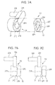
- FIG. 7A depicts the shape of an example of the depression and projection section VX provided in a face of the first clamp 21 on the side where the second clamp 22 is located and in a face of the second clamp 22 on the side where the first clamp 21 is located.
- the depression and projection section VX on the side where the first clamp 21 is located includes two depressions 21C and two projections 21B, and the depression and projection section VX on the side where the second clamp 22 is located includes two depressions 22C and two projections 22B.
- a hole 21H for placing the shaft 11 therethrough is provided in the first clamp 21, and a hole 22H for placing the shaft 11 therethrough is also provided in the second clamp 22.
- the hole 21H is a circular hole, and the hole 22H has a parallel face 22P corresponding to the parallel face 11P of the shaft 11. Therefore, the depression and projection section VX provided between the first clamp 21 and the second clamp 22 has an annular shape.
- FIG. 7C depicts a state in which the projection 22B of the second clamp 22 runs upon the projection 21B of the first clamp 21.
- a friction force is generated in a contact face between the projection 21B of the first clamp 21 and the projection 22B of the second clamp 22.
- FIG. 7B may be brought about when the electronic device 3 depicted in FIG. 3A is closed, and the state depicted in FIG. 7C may be brought about when the electronic device 3 is open.
- the state depicted in FIG. 7B may be brought about when the display section 2 is fully opened with respect to the main body section 1.
- the depression and projection section VX is also called a drawing mechanism.
- the depression and the projection are made to have the same length for ease of explanation.
- the projection it is possible to increase the friction torque in a predetermined region in which the first clamp 21 rotates with respect to the second clamp 22. That is, it is possible to configure the depression and projection section VX provided between the first clamp 21 and the second clamp 22 in such a way that the projections face each other in a predetermined rotation region of the lever 12 and the depression and the projection face each other in the other rotation region.
- the hinge device 10 of this embodiment with the above-described structure may obtain higher friction torque as compared to the hinge device 9 described in the comparative technique.
- the hinge device 9 described in the comparative technique As depicted in FIG. 4A , in the example of this embodiment, three frictional surfaces TP are present. Therefore, the friction torque on one frictional surface TP in the hinge device 10 depicted in FIG. 4A will be described by using a model of a conical friction plate depicted in FIG. 5A .
- the outside diameter of two conical friction plates 31 and 32 is assumed to be ⁇ 1
- the inside diameter thereof is assumed to be ⁇ 2
- the coefficient of friction of the frictional surfaces of the two conical friction plates 31 and 32 is assumed to be ⁇
- the friction torque produced when the applied pressure applied to the two conical friction plates 31 and 32 is F is assumed to be T.
- the angle of a cone is assumed to be ⁇
- the applied pressure in the normal direction of the two conical friction plates 31 and 32 when the applied pressure F is applied is assumed to be Fn.
- the table depicted in FIG. 5B indicates a calculation example of the equivalent friction radius Rw and the magnitude of the friction torque T in the comparative technique using the annular friction plates 51 and 52 with an outside diameter ⁇ 1 of 7 mm and an inside diameter ⁇ 2 of 3 mm and in the embodiment using the conical friction plates 31 and 32 with an outside diameter ⁇ 1 of 5 mm and an inside diameter ⁇ 2 of 3 mm.
- the friction torque T of the friction plates 31 and 32 of the embodiment is higher.
- the applied pressure Fn which is exerted on the conical surfaces of the friction plates 31 and 32 of the embodiment depends on the coefficient of friction ⁇ , if the angle ⁇ of a cone is set at about 30 degrees, it is possible to make the friction torque T of the conical friction plates 31 and 32 of the embodiment higher than the friction torque T of the annular friction plates 51 and 52 of the comparative technique.
- the friction force is unrelated to the contact area between the two friction plates, it is possible to increase the friction force by increasing the applied pressure Fn in the normal direction, the applied pressure Fn acting on the side faces of the two conical friction plates 31 and 32.
- FIG. 6A depicts a model indicating a state in which the outside diameter ⁇ is set at 5 mm and the applied pressure F is applied in the hinge device 10 of the embodiment.
- the friction torque T2 of this model is the sum of the friction torque between the three conical friction plates and the friction torque between one annular friction plate. Assume that the angle ⁇ of a cone in the frictional surface TP is 30 degrees. Then, the friction torque T2 at this time is given by formula (6) below.
- FIG. 6B depicts a model indicating a state in which the outside diameter ⁇ is set at 7 mm and the applied pressure F is applied in the hinge device 9 of the comparative technique.
- the friction torque T1 of this model is the sum of the friction torque between the four annular friction plates.
- the friction torque T1 at this time is given by formula (7) below.
- the hinge device of the embodiment since the value in formula (6) is greater than the value in formula (7), according to the hinge device of the embodiment, it is possible to generate desired high friction torque even when the outside diameter of the hinge device is reduced from 7 mm to 5 mm, and it is possible to implement a slim notebook computer. Moreover, since it is possible to adjust the friction torque by the conical angle of the conical friction plate, it is possible to set a plurality of friction torques even in the hinge device with the same outside diameter. That is, even when the coefficient of friction ⁇ between the friction members of the hinge device and the applied pressure F are fixed, it is possible to adjust the friction torque by varying the conical angle of the conical friction plate.
Landscapes
- Engineering & Computer Science (AREA)
- Computer Hardware Design (AREA)
- Theoretical Computer Science (AREA)
- Human Computer Interaction (AREA)
- Physics & Mathematics (AREA)
- General Engineering & Computer Science (AREA)
- General Physics & Mathematics (AREA)
- Mechanical Engineering (AREA)
- Pivots And Pivotal Connections (AREA)
- Casings For Electric Apparatus (AREA)
Applications Claiming Priority (1)
| Application Number | Priority Date | Filing Date | Title |
|---|---|---|---|
| JP2013082441A JP6142636B2 (ja) | 2013-04-10 | 2013-04-10 | ヒンジ装置 |
Publications (3)
| Publication Number | Publication Date |
|---|---|
| EP2790084A2 true EP2790084A2 (fr) | 2014-10-15 |
| EP2790084A3 EP2790084A3 (fr) | 2014-11-12 |
| EP2790084B1 EP2790084B1 (fr) | 2017-08-30 |
Family
ID=50280134
Family Applications (1)
| Application Number | Title | Priority Date | Filing Date |
|---|---|---|---|
| EP14158020.9A Not-in-force EP2790084B1 (fr) | 2013-04-10 | 2014-03-06 | Dispositif à charnière |
Country Status (5)
| Country | Link |
|---|---|
| US (1) | US9388617B2 (fr) |
| EP (1) | EP2790084B1 (fr) |
| JP (1) | JP6142636B2 (fr) |
| CN (1) | CN104100631A (fr) |
| TW (1) | TWI554689B (fr) |
Families Citing this family (16)
| Publication number | Priority date | Publication date | Assignee | Title |
|---|---|---|---|---|
| US9729766B2 (en) * | 2014-05-19 | 2017-08-08 | Ricoh Imaging Company, Ltd. | Hinge structure, support structure and electric apparatus |
| US9309708B1 (en) * | 2014-10-07 | 2016-04-12 | Chin-Hsing Horng | Hinge with a male hinge shaft axially movable by a lever |
| JP6766494B2 (ja) * | 2016-07-20 | 2020-10-14 | 株式会社リコー | 画像形成装置 |
| US10768672B2 (en) | 2016-10-07 | 2020-09-08 | Hewlett-Packard Development Company, L.P. | Insert molded hinge |
| TWI668556B (zh) | 2017-02-08 | 2019-08-11 | 仁寶電腦工業股份有限公司 | 電子裝置及其鉸鏈組件 |
| US10732677B2 (en) * | 2017-04-26 | 2020-08-04 | Intel Corporation | Close clearance hinge systems |
| KR20190041065A (ko) * | 2017-10-12 | 2019-04-22 | 에이치피프린팅코리아 유한회사 | 힌지 장치 |
| US10620672B2 (en) * | 2017-12-11 | 2020-04-14 | Microsoft Technology Licensing, Llc | Low profile device hinge assembly |
| CN116507781A (zh) * | 2020-11-11 | 2023-07-28 | 里尔精密制造公司 | 惯性锁定摩擦铰接件 |
| TWM616952U (zh) * | 2021-05-11 | 2021-09-11 | 鑫禾科技股份有限公司 | 單軸鉸鍊 |
| TWI801151B (zh) * | 2022-02-25 | 2023-05-01 | 宏碁股份有限公司 | 可攜式電子裝置 |
| TWI825857B (zh) * | 2022-07-18 | 2023-12-11 | 富世達股份有限公司 | 轉軸裝置 |
| TWI801320B (zh) * | 2022-09-27 | 2023-05-01 | 和碩聯合科技股份有限公司 | 鉸鏈裝置 |
| KR20250051765A (ko) * | 2022-10-07 | 2025-04-17 | 구글 엘엘씨 | 휴대용 디스플레이 디바이스 폴딩 |
| IT202300003513A1 (it) * | 2023-02-27 | 2024-08-27 | Elesa Spa | Cerniera a frizione modulabile |
| US12554289B2 (en) * | 2024-02-22 | 2026-02-17 | Dell Products L.P. | Information handling system hinge having overbend alert |
Citations (1)
| Publication number | Priority date | Publication date | Assignee | Title |
|---|---|---|---|---|
| JP2011033152A (ja) | 2009-08-04 | 2011-02-17 | Tanack:Kk | ヒンジ装置 |
Family Cites Families (42)
| Publication number | Priority date | Publication date | Assignee | Title |
|---|---|---|---|---|
| US365413A (en) * | 1887-06-28 | Thill-coupling | ||
| US540764A (en) * | 1895-06-11 | Artificial-leg joint | ||
| US595789A (en) * | 1897-12-21 | Fence-coupling | ||
| US1610404A (en) * | 1925-08-19 | 1926-12-14 | Winfrey Edgar Major | Doorcheck |
| US2862229A (en) * | 1952-02-07 | 1958-12-02 | Charles R Bacca | Spring tensioned radially compressible and longitudinally extensible sectional clamp sleeve |
| FR2582845B1 (fr) * | 1985-06-03 | 1987-08-28 | Selmer Cie Henri | Guide d'axe d'articulation notamment pour instrument de musique |
| US4620344A (en) * | 1985-08-15 | 1986-11-04 | General Electric Company | Friction applying assembly |
| US5333356A (en) * | 1991-11-01 | 1994-08-02 | Santo Industries Co., Ltd. | Assembly for controlling turn of a hinge pivot |
| US5239731A (en) * | 1992-06-03 | 1993-08-31 | Lu Sheng N | Hinge device for casings |
| US5715576A (en) * | 1997-02-04 | 1998-02-10 | Liu; Tai-Sheng | Hinge device for coupling two rotatable members |
| JP3798899B2 (ja) * | 1998-01-27 | 2006-07-19 | 加藤電機株式会社 | チルトヒンジ |
| FI982564L (fi) * | 1998-11-26 | 2000-05-27 | Nokia Mobile Phones Ltd | Saranoitu elektroninen laite |
| JP2000356214A (ja) * | 1999-06-16 | 2000-12-26 | Minoru Kida | ノートパソコン等に使用されるヒンジ装置のプラスチックスプリング並びにプラスチックスプリング圧力受け装置 |
| KR100390410B1 (ko) * | 2000-06-20 | 2003-07-07 | 엘지전자 주식회사 | 힌지 조립체 |
| US20020112319A1 (en) * | 2001-02-21 | 2002-08-22 | Makoto Kida | Hinge |
| JP2003090328A (ja) * | 2001-09-13 | 2003-03-28 | Yashiro Denki Kk | ヒンジ装置 |
| CN1279418C (zh) * | 2001-12-24 | 2006-10-11 | Lg电子株式会社 | 用于平板显示器设备的铰接组件 |
| TW566580U (en) * | 2002-01-30 | 2003-12-11 | Chung-Nan Hsieh | Pivotal hinge and slit-type conical elastic pad |
| US20050081334A1 (en) * | 2003-10-15 | 2005-04-21 | Tai Wen H. | Hinge structure |
| US7003852B2 (en) * | 2003-10-25 | 2006-02-28 | Chuang Wen-Pin | Adjustable stepless hinge shaft |
| US20060272127A1 (en) * | 2005-06-06 | 2006-12-07 | Ray Home Precision Industrial Co., Ltd. | Continuously positioned hinge |
| CN101140009B (zh) * | 2006-09-08 | 2011-11-09 | 鸿富锦精密工业(深圳)有限公司 | 铰链结构及应用该铰链结构的折叠式电子装置 |
| DE202007009824U1 (de) * | 2007-07-10 | 2008-11-20 | Brose Fahrzeugteile Gmbh & Co. Kommanditgesellschaft, Coburg | Feststellvorrichtung eines Kraftfahrzeugs zum Arretieren eines verlagerbaren Kraftfahrzeugteiles |
| TW200920238A (en) * | 2007-10-25 | 2009-05-01 | Jarllytec Co Ltd | Wrapped shaft structure with automatic lock function |
| JP2009145927A (ja) | 2007-12-11 | 2009-07-02 | Lenovo Singapore Pte Ltd | ポータブル電子機器 |
| CN101469737A (zh) * | 2007-12-28 | 2009-07-01 | 鸿富锦精密工业(深圳)有限公司 | 可调式铰链结构 |
| US7823254B2 (en) * | 2008-02-15 | 2010-11-02 | Leohab Enterprise Co.,Ltd. | Hinge assembly |
| CN201277256Y (zh) * | 2008-08-29 | 2009-07-22 | 鸿富锦精密工业(深圳)有限公司 | 枢纽器 |
| CN101749316B (zh) * | 2008-12-11 | 2014-02-26 | 兆利科技工业股份有限公司 | 开轻关重的转轴结构及其凸轮结构 |
| JP5307637B2 (ja) * | 2009-06-11 | 2013-10-02 | 株式会社パイオラックス | ヒンジ装置 |
| CN201531522U (zh) * | 2009-07-31 | 2010-07-21 | 连鋐科技股份有限公司 | 两段扭力的自动闭合式枢钮器 |
| US20110072619A1 (en) * | 2009-09-28 | 2011-03-31 | Cheng Uei Precision Industry Co., Ltd. | Hinge |
| CN201627818U (zh) | 2009-10-30 | 2010-11-10 | 康准电子科技(昆山)有限公司 | 枢纽器 |
| CN201568447U (zh) * | 2009-10-30 | 2010-09-01 | 康准电子科技(昆山)有限公司 | 枢纽器 |
| CN201661593U (zh) * | 2009-11-20 | 2010-12-01 | 连鋐科技股份有限公司 | 具有缓冲片的自动闭合枢纽器 |
| CN201627819U (zh) * | 2010-01-26 | 2010-11-10 | 康准电子科技(昆山)有限公司 | 枢纽器及干涉组件 |
| US8196262B2 (en) * | 2010-01-26 | 2012-06-12 | Hon Hai Precision Industry Co., Ltd. | Hinge |
| JP2011214328A (ja) * | 2010-03-31 | 2011-10-27 | Strawberry Corporation | ヒンジ装置並びにヒンジ装置を用いた電子機器 |
| TW201137253A (en) * | 2010-04-23 | 2011-11-01 | Hon Hai Prec Ind Co Ltd | Hinge |
| JP5228003B2 (ja) * | 2010-07-20 | 2013-07-03 | 森六テクノロジー株式会社 | 車両用物入れ装置のヒンジ構造 |
| CN202690736U (zh) * | 2012-07-19 | 2013-01-23 | 连鋐科技股份有限公司 | 电子设备多段式扭力强化支撑装置 |
| CN104141679A (zh) * | 2013-05-07 | 2014-11-12 | 纬创资通股份有限公司 | 电子装置及枢轴结构 |
-
2013
- 2013-04-10 JP JP2013082441A patent/JP6142636B2/ja not_active Expired - Fee Related
-
2014
- 2014-02-28 US US14/193,404 patent/US9388617B2/en active Active
- 2014-03-05 TW TW103107490A patent/TWI554689B/zh not_active IP Right Cessation
- 2014-03-06 EP EP14158020.9A patent/EP2790084B1/fr not_active Not-in-force
- 2014-03-12 CN CN201410090217.6A patent/CN104100631A/zh active Pending
Patent Citations (1)
| Publication number | Priority date | Publication date | Assignee | Title |
|---|---|---|---|---|
| JP2011033152A (ja) | 2009-08-04 | 2011-02-17 | Tanack:Kk | ヒンジ装置 |
Also Published As
| Publication number | Publication date |
|---|---|
| EP2790084B1 (fr) | 2017-08-30 |
| US20140304948A1 (en) | 2014-10-16 |
| EP2790084A3 (fr) | 2014-11-12 |
| TW201447125A (zh) | 2014-12-16 |
| JP6142636B2 (ja) | 2017-07-12 |
| US9388617B2 (en) | 2016-07-12 |
| JP2014206180A (ja) | 2014-10-30 |
| TWI554689B (zh) | 2016-10-21 |
| CN104100631A (zh) | 2014-10-15 |
Similar Documents
| Publication | Publication Date | Title |
|---|---|---|
| EP2790084B1 (fr) | Dispositif à charnière | |
| US20170344067A1 (en) | Pivot structure and electronic device having the same | |
| JP6197327B2 (ja) | 電子機器 | |
| US20180024589A1 (en) | Portable information device | |
| US20150160695A1 (en) | Hinge unit with simultaneous rotatable axles | |
| US8988863B2 (en) | Portable electronic device | |
| EP2546719A2 (fr) | Charnière pour dispositif électronique | |
| US8964381B2 (en) | Electronic device locking/unlocking mechanism | |
| CN101516169B (zh) | 电子设备 | |
| JP2011231923A (ja) | ヒンジ装置 | |
| CN209327901U (zh) | 弯折结构及柔性屏显示设备 | |
| US20130127318A1 (en) | Clamshell device | |
| US8422211B2 (en) | Assembling/disassembling keyboard structure for a portable device | |
| JP6388301B2 (ja) | ヒンジ装置並びに情報端末 | |
| US20140021727A1 (en) | Opening-aid locking/unlocking mechanism of electronic device | |
| TWI516195B (zh) | 電子裝置 | |
| TWI587777B (zh) | 支撐機構及可攜式電子裝置 | |
| JP5598776B2 (ja) | ヒンジ装置 | |
| JP3161848U (ja) | ばねユニット及びスライド機構 | |
| US9739413B2 (en) | Electronic device and device-securing structure thereof | |
| US10496139B2 (en) | Hinge structure and electronic device | |
| CN103089878A (zh) | 扭簧及使用该扭簧的掀盖式设备 | |
| CN104006067B (zh) | 枢接结构及应用该枢接结构的电子装置 | |
| JP4016503B2 (ja) | 開閉蓋を有する電子機器 | |
| CN107608450B (zh) | 连接装置及电子设备 |
Legal Events
| Date | Code | Title | Description |
|---|---|---|---|
| PUAL | Search report despatched |
Free format text: ORIGINAL CODE: 0009013 |
|
| PUAI | Public reference made under article 153(3) epc to a published international application that has entered the european phase |
Free format text: ORIGINAL CODE: 0009012 |
|
| 17P | Request for examination filed |
Effective date: 20140306 |
|
| AK | Designated contracting states |
Kind code of ref document: A2 Designated state(s): AL AT BE BG CH CY CZ DE DK EE ES FI FR GB GR HR HU IE IS IT LI LT LU LV MC MK MT NL NO PL PT RO RS SE SI SK SM TR |
|
| AX | Request for extension of the european patent |
Extension state: BA ME |
|
| AK | Designated contracting states |
Kind code of ref document: A3 Designated state(s): AL AT BE BG CH CY CZ DE DK EE ES FI FR GB GR HR HU IE IS IT LI LT LU LV MC MK MT NL NO PL PT RO RS SE SI SK SM TR |
|
| AX | Request for extension of the european patent |
Extension state: BA ME |
|
| RIC1 | Information provided on ipc code assigned before grant |
Ipc: H04M 1/02 20060101ALI20141009BHEP Ipc: G06F 1/16 20060101AFI20141009BHEP Ipc: E05D 11/08 20060101ALI20141009BHEP |
|
| R17P | Request for examination filed (corrected) |
Effective date: 20150218 |
|
| RBV | Designated contracting states (corrected) |
Designated state(s): AL AT BE BG CH CY CZ DE DK EE ES FI FR GB GR HR HU IE IS IT LI LT LU LV MC MK MT NL NO PL PT RO RS SE SI SK SM TR |
|
| GRAP | Despatch of communication of intention to grant a patent |
Free format text: ORIGINAL CODE: EPIDOSNIGR1 |
|
| INTG | Intention to grant announced |
Effective date: 20170323 |
|
| GRAS | Grant fee paid |
Free format text: ORIGINAL CODE: EPIDOSNIGR3 |
|
| GRAA | (expected) grant |
Free format text: ORIGINAL CODE: 0009210 |
|
| AK | Designated contracting states |
Kind code of ref document: B1 Designated state(s): AL AT BE BG CH CY CZ DE DK EE ES FI FR GB GR HR HU IE IS IT LI LT LU LV MC MK MT NL NO PL PT RO RS SE SI SK SM TR |
|
| REG | Reference to a national code |
Ref country code: GB Ref legal event code: FG4D |
|
| REG | Reference to a national code |
Ref country code: CH Ref legal event code: EP |
|
| REG | Reference to a national code |
Ref country code: AT Ref legal event code: REF Ref document number: 924170 Country of ref document: AT Kind code of ref document: T Effective date: 20170915 |
|
| REG | Reference to a national code |
Ref country code: IE Ref legal event code: FG4D |
|
| REG | Reference to a national code |
Ref country code: DE Ref legal event code: R096 Ref document number: 602014013690 Country of ref document: DE |
|
| REG | Reference to a national code |
Ref country code: NL Ref legal event code: MP Effective date: 20170830 |
|
| REG | Reference to a national code |
Ref country code: LT Ref legal event code: MG4D |
|
| REG | Reference to a national code |
Ref country code: FR Ref legal event code: PLFP Year of fee payment: 5 |
|
| REG | Reference to a national code |
Ref country code: AT Ref legal event code: MK05 Ref document number: 924170 Country of ref document: AT Kind code of ref document: T Effective date: 20170830 |
|
| PG25 | Lapsed in a contracting state [announced via postgrant information from national office to epo] |
Ref country code: SE Free format text: LAPSE BECAUSE OF FAILURE TO SUBMIT A TRANSLATION OF THE DESCRIPTION OR TO PAY THE FEE WITHIN THE PRESCRIBED TIME-LIMIT Effective date: 20170830 Ref country code: NO Free format text: LAPSE BECAUSE OF FAILURE TO SUBMIT A TRANSLATION OF THE DESCRIPTION OR TO PAY THE FEE WITHIN THE PRESCRIBED TIME-LIMIT Effective date: 20171130 Ref country code: FI Free format text: LAPSE BECAUSE OF FAILURE TO SUBMIT A TRANSLATION OF THE DESCRIPTION OR TO PAY THE FEE WITHIN THE PRESCRIBED TIME-LIMIT Effective date: 20170830 Ref country code: HR Free format text: LAPSE BECAUSE OF FAILURE TO SUBMIT A TRANSLATION OF THE DESCRIPTION OR TO PAY THE FEE WITHIN THE PRESCRIBED TIME-LIMIT Effective date: 20170830 Ref country code: AT Free format text: LAPSE BECAUSE OF FAILURE TO SUBMIT A TRANSLATION OF THE DESCRIPTION OR TO PAY THE FEE WITHIN THE PRESCRIBED TIME-LIMIT Effective date: 20170830 Ref country code: LT Free format text: LAPSE BECAUSE OF FAILURE TO SUBMIT A TRANSLATION OF THE DESCRIPTION OR TO PAY THE FEE WITHIN THE PRESCRIBED TIME-LIMIT Effective date: 20170830 |
|
| PG25 | Lapsed in a contracting state [announced via postgrant information from national office to epo] |
Ref country code: LV Free format text: LAPSE BECAUSE OF FAILURE TO SUBMIT A TRANSLATION OF THE DESCRIPTION OR TO PAY THE FEE WITHIN THE PRESCRIBED TIME-LIMIT Effective date: 20170830 Ref country code: GR Free format text: LAPSE BECAUSE OF FAILURE TO SUBMIT A TRANSLATION OF THE DESCRIPTION OR TO PAY THE FEE WITHIN THE PRESCRIBED TIME-LIMIT Effective date: 20171201 Ref country code: RS Free format text: LAPSE BECAUSE OF FAILURE TO SUBMIT A TRANSLATION OF THE DESCRIPTION OR TO PAY THE FEE WITHIN THE PRESCRIBED TIME-LIMIT Effective date: 20170830 Ref country code: ES Free format text: LAPSE BECAUSE OF FAILURE TO SUBMIT A TRANSLATION OF THE DESCRIPTION OR TO PAY THE FEE WITHIN THE PRESCRIBED TIME-LIMIT Effective date: 20170830 Ref country code: IS Free format text: LAPSE BECAUSE OF FAILURE TO SUBMIT A TRANSLATION OF THE DESCRIPTION OR TO PAY THE FEE WITHIN THE PRESCRIBED TIME-LIMIT Effective date: 20171230 Ref country code: BG Free format text: LAPSE BECAUSE OF FAILURE TO SUBMIT A TRANSLATION OF THE DESCRIPTION OR TO PAY THE FEE WITHIN THE PRESCRIBED TIME-LIMIT Effective date: 20171130 |
|
| PG25 | Lapsed in a contracting state [announced via postgrant information from national office to epo] |
Ref country code: NL Free format text: LAPSE BECAUSE OF FAILURE TO SUBMIT A TRANSLATION OF THE DESCRIPTION OR TO PAY THE FEE WITHIN THE PRESCRIBED TIME-LIMIT Effective date: 20170830 |
|
| PG25 | Lapsed in a contracting state [announced via postgrant information from national office to epo] |
Ref country code: DK Free format text: LAPSE BECAUSE OF FAILURE TO SUBMIT A TRANSLATION OF THE DESCRIPTION OR TO PAY THE FEE WITHIN THE PRESCRIBED TIME-LIMIT Effective date: 20170830 Ref country code: PL Free format text: LAPSE BECAUSE OF FAILURE TO SUBMIT A TRANSLATION OF THE DESCRIPTION OR TO PAY THE FEE WITHIN THE PRESCRIBED TIME-LIMIT Effective date: 20170830 Ref country code: RO Free format text: LAPSE BECAUSE OF FAILURE TO SUBMIT A TRANSLATION OF THE DESCRIPTION OR TO PAY THE FEE WITHIN THE PRESCRIBED TIME-LIMIT Effective date: 20170830 Ref country code: CZ Free format text: LAPSE BECAUSE OF FAILURE TO SUBMIT A TRANSLATION OF THE DESCRIPTION OR TO PAY THE FEE WITHIN THE PRESCRIBED TIME-LIMIT Effective date: 20170830 |
|
| PG25 | Lapsed in a contracting state [announced via postgrant information from national office to epo] |
Ref country code: SM Free format text: LAPSE BECAUSE OF FAILURE TO SUBMIT A TRANSLATION OF THE DESCRIPTION OR TO PAY THE FEE WITHIN THE PRESCRIBED TIME-LIMIT Effective date: 20170830 Ref country code: EE Free format text: LAPSE BECAUSE OF FAILURE TO SUBMIT A TRANSLATION OF THE DESCRIPTION OR TO PAY THE FEE WITHIN THE PRESCRIBED TIME-LIMIT Effective date: 20170830 Ref country code: IT Free format text: LAPSE BECAUSE OF FAILURE TO SUBMIT A TRANSLATION OF THE DESCRIPTION OR TO PAY THE FEE WITHIN THE PRESCRIBED TIME-LIMIT Effective date: 20170830 Ref country code: SK Free format text: LAPSE BECAUSE OF FAILURE TO SUBMIT A TRANSLATION OF THE DESCRIPTION OR TO PAY THE FEE WITHIN THE PRESCRIBED TIME-LIMIT Effective date: 20170830 |
|
| REG | Reference to a national code |
Ref country code: DE Ref legal event code: R097 Ref document number: 602014013690 Country of ref document: DE |
|
| PLBE | No opposition filed within time limit |
Free format text: ORIGINAL CODE: 0009261 |
|
| STAA | Information on the status of an ep patent application or granted ep patent |
Free format text: STATUS: NO OPPOSITION FILED WITHIN TIME LIMIT |
|
| 26N | No opposition filed |
Effective date: 20180531 |
|
| PG25 | Lapsed in a contracting state [announced via postgrant information from national office to epo] |
Ref country code: SI Free format text: LAPSE BECAUSE OF FAILURE TO SUBMIT A TRANSLATION OF THE DESCRIPTION OR TO PAY THE FEE WITHIN THE PRESCRIBED TIME-LIMIT Effective date: 20170830 |
|
| REG | Reference to a national code |
Ref country code: CH Ref legal event code: PL |
|
| PG25 | Lapsed in a contracting state [announced via postgrant information from national office to epo] |
Ref country code: MC Free format text: LAPSE BECAUSE OF FAILURE TO SUBMIT A TRANSLATION OF THE DESCRIPTION OR TO PAY THE FEE WITHIN THE PRESCRIBED TIME-LIMIT Effective date: 20170830 |
|
| REG | Reference to a national code |
Ref country code: BE Ref legal event code: MM Effective date: 20180331 |
|
| REG | Reference to a national code |
Ref country code: IE Ref legal event code: MM4A |
|
| PG25 | Lapsed in a contracting state [announced via postgrant information from national office to epo] |
Ref country code: LU Free format text: LAPSE BECAUSE OF NON-PAYMENT OF DUE FEES Effective date: 20180306 |
|
| PG25 | Lapsed in a contracting state [announced via postgrant information from national office to epo] |
Ref country code: IE Free format text: LAPSE BECAUSE OF NON-PAYMENT OF DUE FEES Effective date: 20180306 |
|
| PG25 | Lapsed in a contracting state [announced via postgrant information from national office to epo] |
Ref country code: BE Free format text: LAPSE BECAUSE OF NON-PAYMENT OF DUE FEES Effective date: 20180331 Ref country code: LI Free format text: LAPSE BECAUSE OF NON-PAYMENT OF DUE FEES Effective date: 20180331 Ref country code: CH Free format text: LAPSE BECAUSE OF NON-PAYMENT OF DUE FEES Effective date: 20180331 |
|
| PG25 | Lapsed in a contracting state [announced via postgrant information from national office to epo] |
Ref country code: MT Free format text: LAPSE BECAUSE OF NON-PAYMENT OF DUE FEES Effective date: 20180306 |
|
| PG25 | Lapsed in a contracting state [announced via postgrant information from national office to epo] |
Ref country code: TR Free format text: LAPSE BECAUSE OF FAILURE TO SUBMIT A TRANSLATION OF THE DESCRIPTION OR TO PAY THE FEE WITHIN THE PRESCRIBED TIME-LIMIT Effective date: 20170830 |
|
| PG25 | Lapsed in a contracting state [announced via postgrant information from national office to epo] |
Ref country code: PT Free format text: LAPSE BECAUSE OF FAILURE TO SUBMIT A TRANSLATION OF THE DESCRIPTION OR TO PAY THE FEE WITHIN THE PRESCRIBED TIME-LIMIT Effective date: 20170830 Ref country code: HU Free format text: LAPSE BECAUSE OF FAILURE TO SUBMIT A TRANSLATION OF THE DESCRIPTION OR TO PAY THE FEE WITHIN THE PRESCRIBED TIME-LIMIT; INVALID AB INITIO Effective date: 20140306 |
|
| PG25 | Lapsed in a contracting state [announced via postgrant information from national office to epo] |
Ref country code: CY Free format text: LAPSE BECAUSE OF FAILURE TO SUBMIT A TRANSLATION OF THE DESCRIPTION OR TO PAY THE FEE WITHIN THE PRESCRIBED TIME-LIMIT Effective date: 20170830 Ref country code: MK Free format text: LAPSE BECAUSE OF NON-PAYMENT OF DUE FEES Effective date: 20170830 |
|
| PG25 | Lapsed in a contracting state [announced via postgrant information from national office to epo] |
Ref country code: AL Free format text: LAPSE BECAUSE OF FAILURE TO SUBMIT A TRANSLATION OF THE DESCRIPTION OR TO PAY THE FEE WITHIN THE PRESCRIBED TIME-LIMIT Effective date: 20170830 |
|
| REG | Reference to a national code |
Ref country code: DE Ref legal event code: R082 Ref document number: 602014013690 Country of ref document: DE Representative=s name: HL KEMPNER PATENTANWAELTE, SOLICITORS (ENGLAND, DE Ref country code: DE Ref legal event code: R082 Ref document number: 602014013690 Country of ref document: DE Representative=s name: HL KEMPNER PATENTANWALT, RECHTSANWALT, SOLICIT, DE |
|
| PGFP | Annual fee paid to national office [announced via postgrant information from national office to epo] |
Ref country code: FR Payment date: 20230208 Year of fee payment: 10 |
|
| PGFP | Annual fee paid to national office [announced via postgrant information from national office to epo] |
Ref country code: GB Payment date: 20230202 Year of fee payment: 10 Ref country code: DE Payment date: 20230131 Year of fee payment: 10 |
|
| REG | Reference to a national code |
Ref country code: DE Ref legal event code: R119 Ref document number: 602014013690 Country of ref document: DE |
|
| GBPC | Gb: european patent ceased through non-payment of renewal fee |
Effective date: 20240306 |
|
| PG25 | Lapsed in a contracting state [announced via postgrant information from national office to epo] |
Ref country code: DE Free format text: LAPSE BECAUSE OF NON-PAYMENT OF DUE FEES Effective date: 20241001 |
|
| PG25 | Lapsed in a contracting state [announced via postgrant information from national office to epo] |
Ref country code: GB Free format text: LAPSE BECAUSE OF NON-PAYMENT OF DUE FEES Effective date: 20240306 |
|
| PG25 | Lapsed in a contracting state [announced via postgrant information from national office to epo] |
Ref country code: FR Free format text: LAPSE BECAUSE OF NON-PAYMENT OF DUE FEES Effective date: 20240331 |
|
| PG25 | Lapsed in a contracting state [announced via postgrant information from national office to epo] |
Ref country code: GB Free format text: LAPSE BECAUSE OF NON-PAYMENT OF DUE FEES Effective date: 20240306 Ref country code: FR Free format text: LAPSE BECAUSE OF NON-PAYMENT OF DUE FEES Effective date: 20240331 Ref country code: DE Free format text: LAPSE BECAUSE OF NON-PAYMENT OF DUE FEES Effective date: 20241001 |