EP2790272A2 - Installation de répartition de courant ainsi que sa mise en contact et la protection des lignes qui en sortent - Google Patents
Installation de répartition de courant ainsi que sa mise en contact et la protection des lignes qui en sortent Download PDFInfo
- Publication number
- EP2790272A2 EP2790272A2 EP20140176369 EP14176369A EP2790272A2 EP 2790272 A2 EP2790272 A2 EP 2790272A2 EP 20140176369 EP20140176369 EP 20140176369 EP 14176369 A EP14176369 A EP 14176369A EP 2790272 A2 EP2790272 A2 EP 2790272A2
- Authority
- EP
- European Patent Office
- Prior art keywords
- potential distribution
- busbar
- distribution system
- intermediate element
- rail
- Prior art date
- Legal status (The legal status is an assumption and is not a legal conclusion. Google has not performed a legal analysis and makes no representation as to the accuracy of the status listed.)
- Granted
Links
Images


Classifications
-
- H—ELECTRICITY
- H01—ELECTRIC ELEMENTS
- H01R—ELECTRICALLY-CONDUCTIVE CONNECTIONS; STRUCTURAL ASSOCIATIONS OF A PLURALITY OF MUTUALLY-INSULATED ELECTRICAL CONNECTING ELEMENTS; COUPLING DEVICES; CURRENT COLLECTORS
- H01R31/00—Coupling parts supported only by co-operation with counterpart
- H01R31/02—Intermediate parts for distributing energy to two or more circuits in parallel, e.g. splitter
-
- H—ELECTRICITY
- H01—ELECTRIC ELEMENTS
- H01R—ELECTRICALLY-CONDUCTIVE CONNECTIONS; STRUCTURAL ASSOCIATIONS OF A PLURALITY OF MUTUALLY-INSULATED ELECTRICAL CONNECTING ELEMENTS; COUPLING DEVICES; CURRENT COLLECTORS
- H01R9/00—Structural associations of a plurality of mutually-insulated electrical connecting elements, e.g. terminal strips or terminal blocks; Terminals or binding posts mounted upon a base or in a case; Bases therefor
- H01R9/22—Bases, e.g. strip, block, panel
- H01R9/24—Terminal blocks
- H01R9/2425—Structural association with built-in components
- H01R9/245—Structural association with built-in components with built-in fuse
-
- H—ELECTRICITY
- H01—ELECTRIC ELEMENTS
- H01R—ELECTRICALLY-CONDUCTIVE CONNECTIONS; STRUCTURAL ASSOCIATIONS OF A PLURALITY OF MUTUALLY-INSULATED ELECTRICAL CONNECTING ELEMENTS; COUPLING DEVICES; CURRENT COLLECTORS
- H01R2201/00—Connectors or connections adapted for particular applications
- H01R2201/26—Connectors or connections adapted for particular applications for vehicles
-
- H—ELECTRICITY
- H01—ELECTRIC ELEMENTS
- H01R—ELECTRICALLY-CONDUCTIVE CONNECTIONS; STRUCTURAL ASSOCIATIONS OF A PLURALITY OF MUTUALLY-INSULATED ELECTRICAL CONNECTING ELEMENTS; COUPLING DEVICES; CURRENT COLLECTORS
- H01R9/00—Structural associations of a plurality of mutually-insulated electrical connecting elements, e.g. terminal strips or terminal blocks; Terminals or binding posts mounted upon a base or in a case; Bases therefor
- H01R9/22—Bases, e.g. strip, block, panel
- H01R9/24—Terminal blocks
- H01R9/2458—Electrical interconnections between terminal blocks
Definitions
- the invention relates to a potential distribution system for motor vehicles with which the established cable harnesses can be streamlined.
- the high-current distribution in vehicles is usually via flexible or highly flexible round conductors, which are combined in bundles.
- This type of harnesses are limp and therefore often require an additional dimensionally stable cable channel.
- the contacting of the harnesses can be made only on permanently provided discharges from the wiring harness and from the possibly existing cable channel. Intermediate taps are usually not possible or only with great effort, since they are not intended by design and not wanted.
- preformed, rigid elements are used to stiffen the wiring harness.
- An example of this is from the Siemens patent specification DE 3609704 C2 known.
- the stiffening is achieved here by additional molded plastic elements to which the cable harness is tied.
- the contacting of the individual lines of the wiring harness is carried out on specially provided discharges or structurally provided connectors.
- Halogen lighting for the room lighting of rooms in buildings also known potential distribution systems for 12 volts DC.
- potential distribution systems for 12 volts DC.
- An example of such a potential distribution system is known from DE 10017484 C2 known.
- the conductor track structure is located here on a plastic carrier of the individual rail segments.
- the rail segments with each other are connected with connecting elements to the desired overall layout of the potential distribution system.
- the connection of the halogen lamps should be made via connectors that are plugged onto the ends of the rail segments, similar to the connecting elements.
- junction boxes or junction boxes for busbars.
- Ansteck for the diversion of wiring harnesses on a rail system.
- the housing of the rail system and the Anstecka here are made of a synthetic resin, so that the Ansteck Anlagenkeit with the plastic housing of the rail system can be poured together.
- Junction boxes made of a plastic housing, wherein the junction box is simultaneously formed as a fuse box.
- the solution succeeds mainly with a rail system, which provides on the stock of the busbars a numerical excess of connectivity options for further derivations.
- the unused connection options can be completed with a blanking plug and the required connection options are contacted via an intermediate element, wherein the intermediate element can be designed as a fuse box or as an intermediate plug with integrated fuses.
- the rail system can also be designed as a double rail system.
- a rail can then be switched as a mass return.
- the rail system is then especially for the commercial vehicle sector suitable to be used in the Bordnetze with Massegur arrangement.
- Fig. 1 shows a first embodiment of the potential distribution system, in which an intermediate element 1 is formed as a fuse box and wherein the intermediate element is contacted via a screw 3 to the busbar 2.
- the screw connection is preferably used when the busbar runs on the vehicle underbody of a motor vehicle and a through-hole is made through the underbody. This can be the case at the end of the rail but also along the course.
- the screw connection is materially connected to the rail, for example by welding a threaded bolt in the busbar.
- the intermediate element contains a metallic stamped grid 4, which is enclosed in a housing 5.
- the Stangitter is formed with a plurality of electrical power branches 6. If necessary, a securing element 7 can also be simultaneously inserted in the individual current branches. preferably be contained as a cross-sectional taper in the current branch of the stamped grid.
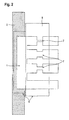
- Fig. 2 shows another embodiment in which the contacting of the intermediate element 1 by means of a plug connection to the busbar 2 takes place.
- one or more contact straps cohesively, for example, by welding, clinching, soldering, etc, attached.
- the outgoing direction of these contacts is preferably rotated by 90 ° relative to the direction of travel of the rail.
- These contact tabs are preferably already encapsulated in the manufacturing process of the potential distribution system below with a molding compound made of plastic. On the one hand, this serves to insulate and protect the contact tabs, on the other hand, the overmoulding, as in connection with the following exemplary embodiments, can also be used as a plug housing.
- the contact tab can be one or more parts in the departure.
- the protective housing 5 is advantageously divided into several chambers. If not all contacts are used depending on the equipment variants, the unused chambers or contacts can be closed with a blanking plug.
- Fig. 3 shows an embodiment in which the intermediate element is designed as an intermediate connector 1a.
- the adapter then also contains the fuse box.
- the box may consist of individual securing elements 7. It is also possible to integrate several current branches and thus also several current branches into the intermediate connector. It is also possible to connect several individual adapter plugs via their housings. These individual intermediate plugs 1a can then, as in the partial view of the Fig. 3a represented by clips or plug-in device, which are as appropriate plug-in elements 8a and recesses 8b in the intermediate connector housing or introduced, are connected together.
- it is also possible retrofits by removing the blind plug on the unused rail side plug-in elements for the adapter plug and inserting additional intermediate plugs make or cover variants.
- the wiring harness for the consumers to be connected is then simply mounted on the output side of a contact tab 9 of the intermediate connector.
- the contact of the intermediate plug with the busbar is also via a plug-in contact tab 10.
- the housing of the rail-side contact tab 10 and the housing 1a of the intermediate plug fit into each other and can be additionally formed with a locking function that supports a secure mechanical existence of the connector.
- the intermediate connector with the integrated fuses may also be integral with a plurality of parallel current branches, e.g. as punched grid solution.
- FIG Fig. 4 Another embodiment of the potential distribution system is shown in FIG Fig. 4 shown.
- the potential distribution system is designed as a double rail system.
- the two busbars 2a, 2b to be contacted may in this case preferably be integrated in a housing 5.
- the outgoing from the busbars contact tabs 10 on different sides of the rails, once on top of the rail 2a and once below the other rail 2b, attached.
- the potentials of these rails can be connected, for example, to the standardized terminals 30, that is to say the input of the battery plus, and to the potential of the terminal 15, that is to say the output for ignition or travel switch, or to the switched terminal 30.
- fuses are used on the top and bottom.
- the potential distribution on the two busbars can also be selected such that one busbar is at the potential of the terminal 30, while the other busbar is at the potential of the terminal 31, ie return to the battery or minus or ground to the battery.
- Such Massesch entry is used for example in on-board networks of commercial vehicles. It would be sufficient if a fuse was integrated at the connection to the busbar with the potential of the terminal 30, a second fuse in the ground current path can be omitted.
- the two busbar housings to be laid side by side are matched to each other, so that, for example, the housing of one busbar projects beyond the housing of the other busbar so that the projecting height is sufficient to make contact with the busbar with an intermediate plug in the region of the projecting height perform. This is especially the case when this protruding height is greater than the height of the intermediate connector.
- control devices can also be connected directly to the rail system.
- two or more rails can be used in a plane, which then several potentials can be distributed.
- the terminal straps can be arranged either offset laterally or one above the other.
Landscapes
- Details Of Connecting Devices For Male And Female Coupling (AREA)
- Fuses (AREA)
- Connection Or Junction Boxes (AREA)
- Connector Housings Or Holding Contact Members (AREA)
Priority Applications (1)
| Application Number | Priority Date | Filing Date | Title |
|---|---|---|---|
| EP19168557.7A EP3534466B1 (fr) | 2006-03-03 | 2007-03-01 | Agencement destiné à la distribution de courant ainsi que sa mise en contact et sécurisation des conduites sortantes |
Applications Claiming Priority (3)
| Application Number | Priority Date | Filing Date | Title |
|---|---|---|---|
| DE102006009936A DE102006009936A1 (de) | 2006-03-03 | 2006-03-03 | Anordnung zur Stromverteilung sowie deren Kontaktierung und Absicherung der abgehenden Leitungen |
| PCT/EP2007/001741 WO2007101596A1 (fr) | 2006-03-03 | 2007-03-01 | Installation de répartition de courant ainsi que sa mise en contact et la protection des lignes qui en sortent |
| EP07711718.2A EP1992047B1 (fr) | 2006-03-03 | 2007-03-01 | Installation de répartition de courant ainsi que sa mise en contact et la protection des lignes qui en sortent |
Related Parent Applications (1)
| Application Number | Title | Priority Date | Filing Date |
|---|---|---|---|
| EP07711718.2A Division EP1992047B1 (fr) | 2006-03-03 | 2007-03-01 | Installation de répartition de courant ainsi que sa mise en contact et la protection des lignes qui en sortent |
Related Child Applications (1)
| Application Number | Title | Priority Date | Filing Date |
|---|---|---|---|
| EP19168557.7A Division EP3534466B1 (fr) | 2006-03-03 | 2007-03-01 | Agencement destiné à la distribution de courant ainsi que sa mise en contact et sécurisation des conduites sortantes |
Publications (3)
| Publication Number | Publication Date |
|---|---|
| EP2790272A2 true EP2790272A2 (fr) | 2014-10-15 |
| EP2790272A3 EP2790272A3 (fr) | 2014-12-17 |
| EP2790272B1 EP2790272B1 (fr) | 2019-05-01 |
Family
ID=38091698
Family Applications (3)
| Application Number | Title | Priority Date | Filing Date |
|---|---|---|---|
| EP19168557.7A Active EP3534466B1 (fr) | 2006-03-03 | 2007-03-01 | Agencement destiné à la distribution de courant ainsi que sa mise en contact et sécurisation des conduites sortantes |
| EP07711718.2A Not-in-force EP1992047B1 (fr) | 2006-03-03 | 2007-03-01 | Installation de répartition de courant ainsi que sa mise en contact et la protection des lignes qui en sortent |
| EP14176369.8A Active EP2790272B1 (fr) | 2006-03-03 | 2007-03-01 | Installation de répartition de courant ainsi que sa mise en contact et la protection des lignes qui en sortent |
Family Applications Before (2)
| Application Number | Title | Priority Date | Filing Date |
|---|---|---|---|
| EP19168557.7A Active EP3534466B1 (fr) | 2006-03-03 | 2007-03-01 | Agencement destiné à la distribution de courant ainsi que sa mise en contact et sécurisation des conduites sortantes |
| EP07711718.2A Not-in-force EP1992047B1 (fr) | 2006-03-03 | 2007-03-01 | Installation de répartition de courant ainsi que sa mise en contact et la protection des lignes qui en sortent |
Country Status (6)
| Country | Link |
|---|---|
| US (1) | US8142235B2 (fr) |
| EP (3) | EP3534466B1 (fr) |
| CN (1) | CN101395762B (fr) |
| DE (1) | DE102006009936A1 (fr) |
| ES (3) | ES2922496T3 (fr) |
| WO (1) | WO2007101596A1 (fr) |
Families Citing this family (13)
| Publication number | Priority date | Publication date | Assignee | Title |
|---|---|---|---|---|
| JP5170305B2 (ja) | 2009-04-03 | 2013-03-27 | 富士通株式会社 | 移動局、無線基地局および無線通信方法 |
| DE102010050124B3 (de) * | 2010-11-03 | 2012-01-26 | Audi Ag | Stromverteilereinrichtung für ein Hochspannungsnetz und Kraftfahrzeug |
| DE102011051320B4 (de) * | 2011-06-24 | 2013-09-05 | Audio Ohm Di Tonani Caterina & C. S.R.L. | Stecksicherung mit verbesserter Auslösecharakteristik |
| DE102012218826A1 (de) * | 2012-10-16 | 2014-04-17 | Tyco Electronics Amp Gmbh | Elektrischer Potenzialverteilungs-Steckadapter, Verfahren zum Bestücken einer elektrischen Verteilereinrichtung |
| JP6308439B2 (ja) * | 2015-02-10 | 2018-04-11 | 株式会社オートネットワーク技術研究所 | 電源分配装置 |
| DE102015202753A1 (de) * | 2015-02-16 | 2016-08-18 | Bayerische Motoren Werke Aktiengesellschaft | Hochvoltsystem |
| US9774179B1 (en) * | 2017-03-30 | 2017-09-26 | Ford Global Technologies, Llc | Fused T-splice wiring |
| US10608301B2 (en) | 2017-08-29 | 2020-03-31 | Nio Usa, Inc. | Power electronics with integrated busbar cooling |
| US10217693B1 (en) * | 2017-08-29 | 2019-02-26 | Nio Usa, Inc. | Methods and systems for high voltage component cooling in electric vehicle for fast charge |
| JP7502203B2 (ja) * | 2021-01-08 | 2024-06-18 | 古河電気工業株式会社 | 分岐接続体、分岐接続体付きハーネス、ハーネス配索構造及び追加回路付きハーネス配索構造 |
| DE102021112304B4 (de) * | 2021-05-11 | 2023-03-30 | Lisa Dräxlmaier GmbH | Kontakteinrichtung und kontaktsystem für eine doppelstromschiene |
| DE102022204677A1 (de) * | 2022-05-12 | 2023-11-16 | Leoni Bordnetz-Systeme Gmbh | Vorrichtung zur elektrischen Leistungsverteilung für ein Kraftfahrzeug |
| DE102024114907A1 (de) * | 2024-05-28 | 2025-12-04 | Bayerische Motoren Werke Aktiengesellschaft | Stromverteilereinheit, Bordnetz sowie Fahrzeug |
Citations (3)
| Publication number | Priority date | Publication date | Assignee | Title |
|---|---|---|---|---|
| DE3609704C2 (de) | 1986-03-20 | 1995-04-20 | Siemens Ag | Kabelbaum für Kraftfahrzeuge |
| EP0722200B1 (fr) | 1995-01-10 | 2001-03-21 | Sumitomo Wiring Systems, Ltd. | Boíte de jonction |
| DE10017484C2 (de) | 2000-04-07 | 2003-10-02 | Ralf Wieduwilt | Niederspannungs-Verteilungssystem |
Family Cites Families (15)
| Publication number | Priority date | Publication date | Assignee | Title |
|---|---|---|---|---|
| US3952209A (en) * | 1974-09-09 | 1976-04-20 | International Telephone And Telegraph Corporation | Electrical system for automotive vehicles and the like |
| IT1030225B (it) * | 1975-02-27 | 1979-03-30 | Fiat Spa | Impianto elettrico in particolare per autoveicoli |
| JPS63109244U (fr) * | 1987-01-08 | 1988-07-14 | ||
| DE3930153A1 (de) | 1989-09-09 | 1991-03-21 | Rheydt Kabelwerk Ag | Verkabelungssystem fuer fahrzeuge |
| US5490794A (en) * | 1993-11-05 | 1996-02-13 | Sumitomo Wiring Systems, Ltd. | Branch joint box |
| US5676558A (en) * | 1995-10-02 | 1997-10-14 | Mayer; E. Howard | Reduced cable requiring, fusible bus duct system and method for providing electrical energy to houses and buildings and the like |
| US5643693A (en) * | 1995-10-30 | 1997-07-01 | Yazaki Corporation | Battery-mounted power distribution module |
| DE19646264C2 (de) * | 1996-11-09 | 2000-10-26 | Wilhelm Pudenz Gmbh Elektrotec | Schmelzleiteraufbau |
| EP0956218B1 (fr) * | 1997-01-30 | 2002-04-03 | The Whitaker Corporation | Distribution d'energie et de signaux en electronique automobile au moyen de modules de secteur et de modules de fonction |
| DE19732697C2 (de) * | 1997-07-30 | 2001-10-04 | Daimler Chrysler Ag | Vorrichtung zum Abzweigen von Kabeln |
| DE69726158T2 (de) * | 1997-12-17 | 2004-08-26 | Meccanotecnica Codognese S.P.A., Codogno | Starkstromschutzvorrichtung |
| DE19906000B4 (de) | 1999-02-15 | 2006-09-28 | Volkswagen Ag | Energieanschlussleiste für Kraftfahrzeuge |
| JP2001054223A (ja) * | 1999-08-06 | 2001-02-23 | Toyota Motor Corp | ヒューズ装置 |
| US20020132515A1 (en) * | 2001-03-19 | 2002-09-19 | Chin-Chuan Hong | Electrical plug with circuit-breaking capability |
| JP2002329453A (ja) * | 2001-04-27 | 2002-11-15 | Yazaki Corp | 連鎖型ヒューズ組立体およびそのレイアウト方法 |
-
2006
- 2006-03-03 DE DE102006009936A patent/DE102006009936A1/de not_active Withdrawn
-
2007
- 2007-03-01 EP EP19168557.7A patent/EP3534466B1/fr active Active
- 2007-03-01 US US12/281,272 patent/US8142235B2/en not_active Expired - Fee Related
- 2007-03-01 WO PCT/EP2007/001741 patent/WO2007101596A1/fr not_active Ceased
- 2007-03-01 CN CN2007800075538A patent/CN101395762B/zh not_active Expired - Fee Related
- 2007-03-01 ES ES19168557T patent/ES2922496T3/es active Active
- 2007-03-01 ES ES14176369T patent/ES2727669T3/es active Active
- 2007-03-01 EP EP07711718.2A patent/EP1992047B1/fr not_active Not-in-force
- 2007-03-01 ES ES07711718.2T patent/ES2502516T3/es active Active
- 2007-03-01 EP EP14176369.8A patent/EP2790272B1/fr active Active
Patent Citations (3)
| Publication number | Priority date | Publication date | Assignee | Title |
|---|---|---|---|---|
| DE3609704C2 (de) | 1986-03-20 | 1995-04-20 | Siemens Ag | Kabelbaum für Kraftfahrzeuge |
| EP0722200B1 (fr) | 1995-01-10 | 2001-03-21 | Sumitomo Wiring Systems, Ltd. | Boíte de jonction |
| DE10017484C2 (de) | 2000-04-07 | 2003-10-02 | Ralf Wieduwilt | Niederspannungs-Verteilungssystem |
Also Published As
| Publication number | Publication date |
|---|---|
| EP1992047B1 (fr) | 2014-07-16 |
| EP2790272A3 (fr) | 2014-12-17 |
| US20090050366A1 (en) | 2009-02-26 |
| EP1992047A1 (fr) | 2008-11-19 |
| CN101395762A (zh) | 2009-03-25 |
| US8142235B2 (en) | 2012-03-27 |
| DE102006009936A1 (de) | 2007-09-06 |
| EP3534466B1 (fr) | 2022-07-06 |
| EP2790272B1 (fr) | 2019-05-01 |
| EP3534466A1 (fr) | 2019-09-04 |
| ES2502516T3 (es) | 2014-10-03 |
| ES2922496T3 (es) | 2022-09-15 |
| ES2727669T3 (es) | 2019-10-17 |
| WO2007101596A1 (fr) | 2007-09-13 |
| CN101395762B (zh) | 2011-04-13 |
Similar Documents
| Publication | Publication Date | Title |
|---|---|---|
| EP2790272B1 (fr) | Installation de répartition de courant ainsi que sa mise en contact et la protection des lignes qui en sortent | |
| EP2473377B1 (fr) | Répartiteur de courant modulaire | |
| DE4438800C1 (de) | Anschlußklemmenblock mit Elektronikmodul | |
| DE19548961C2 (de) | Elektrischer Anschlußkasten | |
| DE102012214366B4 (de) | Schaltvorrichtung für einen Stromschienen-basierten Fahrzeugstromverteiler | |
| EP0209072B1 (fr) | Dispositif pour véhicule | |
| EP3006252B1 (fr) | Distributeur de haute tension pour un vehicule electrique hybride | |
| DE2409660A1 (de) | Elektrische schalt-, steuer- und/oder regeleinrichtung fuer elektrische geraete in einem fahrzeug | |
| DE10248012B4 (de) | Struktur zur Verbindung von Batterieanschlüssen mit Sammelschienen | |
| WO2017046370A1 (fr) | Distributeur de courant muni d'une électronique enfichable | |
| EP1830376B1 (fr) | Dispositif destiné à la distribution de courant | |
| EP2091113B1 (fr) | Système de raccordement pour bandes lumineuses ou lampes | |
| DE102010042158A1 (de) | Elektrisches Verteilergehäuse | |
| DE69513613T2 (de) | Differentialschutzschalter zugeordnet zu einem oder mehreren Schaltungsschutzelementen wie Schmelzsicherungen oder Schutzschalter | |
| DE2340773A1 (de) | Uebergabesteckverbindung | |
| DE102006045859B4 (de) | Potentialverteiler für Kraftfahrzeuge | |
| DE102019103531B4 (de) | Überspannungsableiteranordnung mit in einem gemeinsamen Gehäuse befindlichen, vorkonfektionierten und elektrisch verschalteten Überspannungsableitern | |
| DE102009036599A1 (de) | Hochstromverkabelung | |
| EP1787358B1 (fr) | Module d'alimentation electrique comportant des bornes a ressort de rappel de cage | |
| EP2073314B1 (fr) | Agencement de liaison électrique conductrice des conducteurs électriques | |
| DE102015111885A1 (de) | Sicherung für Stromverteiler | |
| DE202018006111U1 (de) | Überspannungsableiteranordnung mit in einem gemeinsamen Gehäuse befindlichen, vorkonfektionierten und elektrisch verschalteten Überspannungsableitern | |
| EP0999954A1 (fr) | Systeme distributeur de tension destine a la distribution de tension a des consommateurs et connecteurs adaptes | |
| DE102015205450B4 (de) | Hauptsicherungsbox , mit einer Mehrfachsicherung, zur Befestigung an einer Bordnetz-Batterie eines Kraftfahrzeugs | |
| DE202021105885U1 (de) | Kabelanschlusskasten mit Nullleitertrennung |
Legal Events
| Date | Code | Title | Description |
|---|---|---|---|
| PUAI | Public reference made under article 153(3) epc to a published international application that has entered the european phase |
Free format text: ORIGINAL CODE: 0009012 |
|
| 17P | Request for examination filed |
Effective date: 20140709 |
|
| AC | Divisional application: reference to earlier application |
Ref document number: 1992047 Country of ref document: EP Kind code of ref document: P |
|
| AK | Designated contracting states |
Kind code of ref document: A2 Designated state(s): AT BE BG CH CY CZ DE DK EE ES FI FR GB GR HU IE IS IT LI LT LU LV MC MT NL PL PT RO SE SI SK TR |
|
| PUAL | Search report despatched |
Free format text: ORIGINAL CODE: 0009013 |
|
| AK | Designated contracting states |
Kind code of ref document: A3 Designated state(s): AT BE BG CH CY CZ DE DK EE ES FI FR GB GR HU IE IS IT LI LT LU LV MC MT NL PL PT RO SE SI SK TR |
|
| RIC1 | Information provided on ipc code assigned before grant |
Ipc: H01R 31/02 20060101ALI20141111BHEP Ipc: H01R 9/24 20060101AFI20141111BHEP |
|
| R17P | Request for examination filed (corrected) |
Effective date: 20150410 |
|
| RBV | Designated contracting states (corrected) |
Designated state(s): AT BE BG CH CY CZ DE DK EE ES FI FR GB GR HU IE IS IT LI LT LU LV MC MT NL PL PT RO SE SI SK TR |
|
| GRAP | Despatch of communication of intention to grant a patent |
Free format text: ORIGINAL CODE: EPIDOSNIGR1 |
|
| STAA | Information on the status of an ep patent application or granted ep patent |
Free format text: STATUS: GRANT OF PATENT IS INTENDED |
|
| INTG | Intention to grant announced |
Effective date: 20181129 |
|
| GRAS | Grant fee paid |
Free format text: ORIGINAL CODE: EPIDOSNIGR3 |
|
| GRAA | (expected) grant |
Free format text: ORIGINAL CODE: 0009210 |
|
| STAA | Information on the status of an ep patent application or granted ep patent |
Free format text: STATUS: THE PATENT HAS BEEN GRANTED |
|
| AC | Divisional application: reference to earlier application |
Ref document number: 1992047 Country of ref document: EP Kind code of ref document: P |
|
| AK | Designated contracting states |
Kind code of ref document: B1 Designated state(s): AT BE BG CH CY CZ DE DK EE ES FI FR GB GR HU IE IS IT LI LT LU LV MC MT NL PL PT RO SE SI SK TR |
|
| REG | Reference to a national code |
Ref country code: GB Ref legal event code: FG4D Free format text: NOT ENGLISH |
|
| REG | Reference to a national code |
Ref country code: CH Ref legal event code: EP Ref country code: AT Ref legal event code: REF Ref document number: 1128170 Country of ref document: AT Kind code of ref document: T Effective date: 20190515 |
|
| REG | Reference to a national code |
Ref country code: DE Ref legal event code: R096 Ref document number: 502007016665 Country of ref document: DE |
|
| REG | Reference to a national code |
Ref country code: IE Ref legal event code: FG4D Free format text: LANGUAGE OF EP DOCUMENT: GERMAN |
|
| REG | Reference to a national code |
Ref country code: NL Ref legal event code: MP Effective date: 20190501 |
|
| REG | Reference to a national code |
Ref country code: LT Ref legal event code: MG4D |
|
| REG | Reference to a national code |
Ref country code: ES Ref legal event code: FG2A Ref document number: 2727669 Country of ref document: ES Kind code of ref document: T3 Effective date: 20191017 |
|
| PG25 | Lapsed in a contracting state [announced via postgrant information from national office to epo] |
Ref country code: NL Free format text: LAPSE BECAUSE OF FAILURE TO SUBMIT A TRANSLATION OF THE DESCRIPTION OR TO PAY THE FEE WITHIN THE PRESCRIBED TIME-LIMIT Effective date: 20190501 Ref country code: PT Free format text: LAPSE BECAUSE OF FAILURE TO SUBMIT A TRANSLATION OF THE DESCRIPTION OR TO PAY THE FEE WITHIN THE PRESCRIBED TIME-LIMIT Effective date: 20190901 Ref country code: SE Free format text: LAPSE BECAUSE OF FAILURE TO SUBMIT A TRANSLATION OF THE DESCRIPTION OR TO PAY THE FEE WITHIN THE PRESCRIBED TIME-LIMIT Effective date: 20190501 Ref country code: LT Free format text: LAPSE BECAUSE OF FAILURE TO SUBMIT A TRANSLATION OF THE DESCRIPTION OR TO PAY THE FEE WITHIN THE PRESCRIBED TIME-LIMIT Effective date: 20190501 Ref country code: FI Free format text: LAPSE BECAUSE OF FAILURE TO SUBMIT A TRANSLATION OF THE DESCRIPTION OR TO PAY THE FEE WITHIN THE PRESCRIBED TIME-LIMIT Effective date: 20190501 |
|
| PG25 | Lapsed in a contracting state [announced via postgrant information from national office to epo] |
Ref country code: GR Free format text: LAPSE BECAUSE OF FAILURE TO SUBMIT A TRANSLATION OF THE DESCRIPTION OR TO PAY THE FEE WITHIN THE PRESCRIBED TIME-LIMIT Effective date: 20190802 Ref country code: BG Free format text: LAPSE BECAUSE OF FAILURE TO SUBMIT A TRANSLATION OF THE DESCRIPTION OR TO PAY THE FEE WITHIN THE PRESCRIBED TIME-LIMIT Effective date: 20190801 Ref country code: LV Free format text: LAPSE BECAUSE OF FAILURE TO SUBMIT A TRANSLATION OF THE DESCRIPTION OR TO PAY THE FEE WITHIN THE PRESCRIBED TIME-LIMIT Effective date: 20190501 |
|
| PG25 | Lapsed in a contracting state [announced via postgrant information from national office to epo] |
Ref country code: IS Free format text: LAPSE BECAUSE OF FAILURE TO SUBMIT A TRANSLATION OF THE DESCRIPTION OR TO PAY THE FEE WITHIN THE PRESCRIBED TIME-LIMIT Effective date: 20190901 |
|
| PG25 | Lapsed in a contracting state [announced via postgrant information from national office to epo] |
Ref country code: DK Free format text: LAPSE BECAUSE OF FAILURE TO SUBMIT A TRANSLATION OF THE DESCRIPTION OR TO PAY THE FEE WITHIN THE PRESCRIBED TIME-LIMIT Effective date: 20190501 Ref country code: SK Free format text: LAPSE BECAUSE OF FAILURE TO SUBMIT A TRANSLATION OF THE DESCRIPTION OR TO PAY THE FEE WITHIN THE PRESCRIBED TIME-LIMIT Effective date: 20190501 Ref country code: RO Free format text: LAPSE BECAUSE OF FAILURE TO SUBMIT A TRANSLATION OF THE DESCRIPTION OR TO PAY THE FEE WITHIN THE PRESCRIBED TIME-LIMIT Effective date: 20190501 Ref country code: EE Free format text: LAPSE BECAUSE OF FAILURE TO SUBMIT A TRANSLATION OF THE DESCRIPTION OR TO PAY THE FEE WITHIN THE PRESCRIBED TIME-LIMIT Effective date: 20190501 |
|
| REG | Reference to a national code |
Ref country code: DE Ref legal event code: R097 Ref document number: 502007016665 Country of ref document: DE |
|
| PLBE | No opposition filed within time limit |
Free format text: ORIGINAL CODE: 0009261 |
|
| STAA | Information on the status of an ep patent application or granted ep patent |
Free format text: STATUS: NO OPPOSITION FILED WITHIN TIME LIMIT |
|
| PG25 | Lapsed in a contracting state [announced via postgrant information from national office to epo] |
Ref country code: TR Free format text: LAPSE BECAUSE OF FAILURE TO SUBMIT A TRANSLATION OF THE DESCRIPTION OR TO PAY THE FEE WITHIN THE PRESCRIBED TIME-LIMIT Effective date: 20190501 |
|
| 26N | No opposition filed |
Effective date: 20200204 |
|
| PG25 | Lapsed in a contracting state [announced via postgrant information from national office to epo] |
Ref country code: PL Free format text: LAPSE BECAUSE OF FAILURE TO SUBMIT A TRANSLATION OF THE DESCRIPTION OR TO PAY THE FEE WITHIN THE PRESCRIBED TIME-LIMIT Effective date: 20190501 |
|
| PG25 | Lapsed in a contracting state [announced via postgrant information from national office to epo] |
Ref country code: SI Free format text: LAPSE BECAUSE OF FAILURE TO SUBMIT A TRANSLATION OF THE DESCRIPTION OR TO PAY THE FEE WITHIN THE PRESCRIBED TIME-LIMIT Effective date: 20190501 |
|
| PG25 | Lapsed in a contracting state [announced via postgrant information from national office to epo] |
Ref country code: MC Free format text: LAPSE BECAUSE OF FAILURE TO SUBMIT A TRANSLATION OF THE DESCRIPTION OR TO PAY THE FEE WITHIN THE PRESCRIBED TIME-LIMIT Effective date: 20190501 |
|
| REG | Reference to a national code |
Ref country code: CH Ref legal event code: PL |
|
| REG | Reference to a national code |
Ref country code: BE Ref legal event code: MM Effective date: 20200331 |
|
| PG25 | Lapsed in a contracting state [announced via postgrant information from national office to epo] |
Ref country code: LU Free format text: LAPSE BECAUSE OF NON-PAYMENT OF DUE FEES Effective date: 20200301 |
|
| PG25 | Lapsed in a contracting state [announced via postgrant information from national office to epo] |
Ref country code: IE Free format text: LAPSE BECAUSE OF NON-PAYMENT OF DUE FEES Effective date: 20200301 Ref country code: CH Free format text: LAPSE BECAUSE OF NON-PAYMENT OF DUE FEES Effective date: 20200331 Ref country code: LI Free format text: LAPSE BECAUSE OF NON-PAYMENT OF DUE FEES Effective date: 20200331 |
|
| PG25 | Lapsed in a contracting state [announced via postgrant information from national office to epo] |
Ref country code: BE Free format text: LAPSE BECAUSE OF NON-PAYMENT OF DUE FEES Effective date: 20200331 |
|
| PGFP | Annual fee paid to national office [announced via postgrant information from national office to epo] |
Ref country code: GB Payment date: 20220321 Year of fee payment: 16 Ref country code: DE Payment date: 20220321 Year of fee payment: 16 Ref country code: AT Payment date: 20220322 Year of fee payment: 16 |
|
| PG25 | Lapsed in a contracting state [announced via postgrant information from national office to epo] |
Ref country code: MT Free format text: LAPSE BECAUSE OF FAILURE TO SUBMIT A TRANSLATION OF THE DESCRIPTION OR TO PAY THE FEE WITHIN THE PRESCRIBED TIME-LIMIT Effective date: 20190501 Ref country code: CY Free format text: LAPSE BECAUSE OF FAILURE TO SUBMIT A TRANSLATION OF THE DESCRIPTION OR TO PAY THE FEE WITHIN THE PRESCRIBED TIME-LIMIT Effective date: 20190501 |
|
| PGFP | Annual fee paid to national office [announced via postgrant information from national office to epo] |
Ref country code: FR Payment date: 20220321 Year of fee payment: 16 |
|
| PGFP | Annual fee paid to national office [announced via postgrant information from national office to epo] |
Ref country code: IT Payment date: 20220324 Year of fee payment: 16 Ref country code: ES Payment date: 20220420 Year of fee payment: 16 |
|
| PGFP | Annual fee paid to national office [announced via postgrant information from national office to epo] |
Ref country code: CZ Payment date: 20230126 Year of fee payment: 17 |
|
| REG | Reference to a national code |
Ref country code: DE Ref legal event code: R119 Ref document number: 502007016665 Country of ref document: DE |
|
| REG | Reference to a national code |
Ref country code: AT Ref legal event code: MM01 Ref document number: 1128170 Country of ref document: AT Kind code of ref document: T Effective date: 20230301 |
|
| GBPC | Gb: european patent ceased through non-payment of renewal fee |
Effective date: 20230301 |
|
| PG25 | Lapsed in a contracting state [announced via postgrant information from national office to epo] |
Ref country code: GB Free format text: LAPSE BECAUSE OF NON-PAYMENT OF DUE FEES Effective date: 20230301 |
|
| PG25 | Lapsed in a contracting state [announced via postgrant information from national office to epo] |
Ref country code: GB Free format text: LAPSE BECAUSE OF NON-PAYMENT OF DUE FEES Effective date: 20230301 Ref country code: FR Free format text: LAPSE BECAUSE OF NON-PAYMENT OF DUE FEES Effective date: 20230331 Ref country code: DE Free format text: LAPSE BECAUSE OF NON-PAYMENT OF DUE FEES Effective date: 20231003 Ref country code: AT Free format text: LAPSE BECAUSE OF NON-PAYMENT OF DUE FEES Effective date: 20230301 |
|
| PG25 | Lapsed in a contracting state [announced via postgrant information from national office to epo] |
Ref country code: ES Free format text: LAPSE BECAUSE OF NON-PAYMENT OF DUE FEES Effective date: 20230302 |
|
| REG | Reference to a national code |
Ref country code: ES Ref legal event code: FD2A Effective date: 20240426 |
|
| PG25 | Lapsed in a contracting state [announced via postgrant information from national office to epo] |
Ref country code: IT Free format text: LAPSE BECAUSE OF NON-PAYMENT OF DUE FEES Effective date: 20230301 Ref country code: ES Free format text: LAPSE BECAUSE OF NON-PAYMENT OF DUE FEES Effective date: 20230302 |
|
| PG25 | Lapsed in a contracting state [announced via postgrant information from national office to epo] |
Ref country code: CZ Free format text: LAPSE BECAUSE OF NON-PAYMENT OF DUE FEES Effective date: 20240301 |
|
| PG25 | Lapsed in a contracting state [announced via postgrant information from national office to epo] |
Ref country code: CZ Free format text: LAPSE BECAUSE OF NON-PAYMENT OF DUE FEES Effective date: 20240301 |