EP2790432B1 - Drahtlose basisstation, kommunikationssteuerungsverfahren für die drahtlose basisstation und computerprogramm - Google Patents
Drahtlose basisstation, kommunikationssteuerungsverfahren für die drahtlose basisstation und computerprogramm Download PDFInfo
- Publication number
- EP2790432B1 EP2790432B1 EP12856415.0A EP12856415A EP2790432B1 EP 2790432 B1 EP2790432 B1 EP 2790432B1 EP 12856415 A EP12856415 A EP 12856415A EP 2790432 B1 EP2790432 B1 EP 2790432B1
- Authority
- EP
- European Patent Office
- Prior art keywords
- terminal
- base station
- uplink
- femtocell
- allocation
- Prior art date
- Legal status (The legal status is an assumption and is not a legal conclusion. Google has not performed a legal analysis and makes no representation as to the accuracy of the status listed.)
- Not-in-force
Links
Images








Classifications
-
- H—ELECTRICITY
- H04—ELECTRIC COMMUNICATION TECHNIQUE
- H04W—WIRELESS COMMUNICATION NETWORKS
- H04W72/00—Local resource management
- H04W72/50—Allocation or scheduling criteria for wireless resources
- H04W72/56—Allocation or scheduling criteria for wireless resources based on priority criteria
-
- H—ELECTRICITY
- H04—ELECTRIC COMMUNICATION TECHNIQUE
- H04W—WIRELESS COMMUNICATION NETWORKS
- H04W16/00—Network planning, e.g. coverage or traffic planning tools; Network deployment, e.g. resource partitioning or cells structures
- H04W16/14—Spectrum sharing arrangements between different networks
- H04W16/16—Spectrum sharing arrangements between different networks for PBS [Private Base Station] arrangements
-
- H—ELECTRICITY
- H04—ELECTRIC COMMUNICATION TECHNIQUE
- H04L—TRANSMISSION OF DIGITAL INFORMATION, e.g. TELEGRAPHIC COMMUNICATION
- H04L1/00—Arrangements for detecting or preventing errors in the information received
- H04L1/12—Arrangements for detecting or preventing errors in the information received by using return channel
- H04L1/16—Arrangements for detecting or preventing errors in the information received by using return channel in which the return channel carries supervisory signals, e.g. repetition request signals
- H04L1/1607—Details of the supervisory signal
-
- H—ELECTRICITY
- H04—ELECTRIC COMMUNICATION TECHNIQUE
- H04L—TRANSMISSION OF DIGITAL INFORMATION, e.g. TELEGRAPHIC COMMUNICATION
- H04L5/00—Arrangements affording multiple use of the transmission path
- H04L5/003—Arrangements for allocating sub-channels of the transmission path
- H04L5/0048—Allocation of pilot signals, i.e. of signals known to the receiver
-
- H—ELECTRICITY
- H04—ELECTRIC COMMUNICATION TECHNIQUE
- H04L—TRANSMISSION OF DIGITAL INFORMATION, e.g. TELEGRAPHIC COMMUNICATION
- H04L5/00—Arrangements affording multiple use of the transmission path
- H04L5/003—Arrangements for allocating sub-channels of the transmission path
- H04L5/0053—Allocation of signalling, i.e. of overhead other than pilot signals
- H04L5/0055—Physical resource allocation for ACK/NACK
-
- H—ELECTRICITY
- H04—ELECTRIC COMMUNICATION TECHNIQUE
- H04L—TRANSMISSION OF DIGITAL INFORMATION, e.g. TELEGRAPHIC COMMUNICATION
- H04L5/00—Arrangements affording multiple use of the transmission path
- H04L5/003—Arrangements for allocating sub-channels of the transmission path
- H04L5/0058—Allocation criteria
- H04L5/0073—Allocation arrangements that take into account other cell interferences
-
- H—ELECTRICITY
- H04—ELECTRIC COMMUNICATION TECHNIQUE
- H04W—WIRELESS COMMUNICATION NETWORKS
- H04W84/00—Network topologies
- H04W84/02—Hierarchically pre-organised networks, e.g. paging networks, cellular networks, WLAN [Wireless Local Area Network] or WLL [Wireless Local Loop]
- H04W84/04—Large scale networks; Deep hierarchical networks
- H04W84/042—Public Land Mobile systems, e.g. cellular systems
- H04W84/045—Public Land Mobile systems, e.g. cellular systems using private Base Stations, e.g. femto Base Stations, home Node B
Definitions
- the present disclosure relates to a radio base station, a communication control method of a radio base station, and a computer program.
- An indoor low-power base station connects to the Internet or an operator's core network via a broadband line (hereinafter, a BB line) such as ADSL (Asymmetric Digital Subscriber Line), FTTH (Fiber To The Home), and CATV.
- a BB line such as ADSL (Asymmetric Digital Subscriber Line), FTTH (Fiber To The Home), and CATV.
- ADSL Asymmetric Digital Subscriber Line
- FTTH Fiber To The Home
- CATV CATV
- the femtocell is installable in the user's house or office by the user and can limit users (terminals) allowed to use to perform short-distance communication with a data communication terminal in a relatively small service area (coverage). Therefore, the femtocell provides a communication environment of excellent communication quality and high throughput.
- Patent Literature 1 JP 2011-45118A
- Non-Patent Literature 1 3GPP TR 25.967
- the service area of a femtocell overlaps with that of a macrocell.
- the femtocell has a mechanism to limit users (terminals) allowed to use and thus, interference is an important problem and interference avoidance between a femtocell and a macrocell operated at the same frequency is required.
- Interference adjustment methods attempting to reduce interference with a macrocell or a macrocell terminal have been known.
- a macrocell terminal away from a macrocell is located near a femtocell and the macrocell terminal has no access rights to the femtocell
- the macrocell terminal needs large uplink transmission power to allow an uplink transmission wave to reach the distant macrocell and the uplink transmission wave of the macrocell terminal excessively interferes with uplink reception by the nearby femtocell so that deterioration of uplink throughput of the femtocell terminal, interruption of communication and the like could be caused.
- No effective means for reducing interference with a femtocell or a femtocell terminal in uplink of such data communication has been known.
- Patent Literature 1 discloses a technology of countermeasures against uplink interference between base stations.
- the technology disclosed by Patent Literature 1 is a method in which the base station whose uplink is interfered with transmits information about the radio resource that is interfered with to adjacent base stations and the base station using the radio resource changes allocation of radio resources and to realize the method as an interference avoidance method between a femtocell and a macrocell, it is necessary to transmit information about interference between the femtocell and macrocell and if a few thousand femtocells are installed in the area of the macrocell, messages of the interference information needs heavy traffic, posing a problem of imposing strains on overall communication capacities.
- Non-Patent Literature 1 proposes a method of controlling the permissible noise level of uplink concerning measures against uplink interference from a macrocell terminal to a femtocell in the UMTS mobile phone scheme. If, for example, the noise level permitted for uplink reception of the femtocell is raised, transmission power of uplink of the terminal serviced to the femtocell is significantly controlled so that the influence from other terminals on uplink interference can be decreased.
- the present disclosure is developed in view of the above problems and an object thereof is to provide a novel and improved radio base station capable of, when a terminal serviced by a base station other than a femtocell is located near the femtocell and the terminal has no access rights to the femtocell, preventing an uplink transmission wave of the terminal from interfering with uplink reception by the femtocell and easily preventing deterioration of uplink throughput of a femtocell terminal, interruption of communication and the like, a communication control method of a radio base station, and a computer program.
- a novel and improved radio base station capable of, when a terminal serviced from a base station other than a femtocell is located near the femtocell and the terminal has no access rights to the femtocell, preventing an uplink transmission wave of the terminal from interfering with uplink reception by the femtocell and easily preventing deterioration of uplink throughput of a femtocell terminal, interruption of communication and the like, a communication control method of a radio base station, and a computer program can be provided.
- FIG. 1 is an explanatory view showing a configuration example of a general communication system.
- the Internet and a core network A are connected to each other and a macrocell is connected to the core network A and femtocells are connected to the Internet.
- a macrocell terminal (Macro UE) communicating with the macrocell of the core network A
- femtocell terminals (Femto UE) communicating with femtocells are illustrated.
- FIG. 2 is an explanatory view showing an example of a frame format of a downlink signal in the frequency division multiplexing (FDD) LTE scheme.
- FDD frequency division multiplexing
- Physical channels and signals of downlink transmitted by a base station of the LTE scheme to a terminal include a physical down shared channel (PDSCH) to transmit data for individual users, a physical down control channel (PDCCH) to transmit control information of downlink, a physical broadcasting channel (PBCH) to transmit system information needed for a terminal to access a network, a physical hybrid ARQ information channel (PHICH) to transmit an acknowledgement indicating whether to retransmit a transport block to a terminal, a physical control format information channel (PCFICH) to transmit information needed for PDCCH decoding, a downlink reference signal (Reference Signal) used by the terminal to estimate the channel of downlink to perform synchronous detection in a variable down physical channel, and a primary synchronous signal (PSS) and a secondary synchronous signal (SSS) to help a terminal search for a cell to be able to detect a physical layer cell ID (PCI) of the cell, the physical hybrid ARQ information channel (PHICH) and the physical control format information channel (PCFICH) are allocated to
- a terminal detects PCI and frame timing by detecting the primary synchronous signal (PSS) and the secondary synchronous signal (SSS) using a signal sequence corresponding to the physical layer cell ID (PCI) allocated to individual base stations. Because the arrangement of PSS and SSS in a radio frame is different between the frequency division multiplexing (FDD) and time division multiplexing (TDD), the terminal can also determine which of the FDD system and TDD system is used by the searched cell, simultaneously with the detection of PSS and SSS.
- a synchronization signal is always arranged in the band of six resource blocks in the center regardless of the service bandwidth to easily enable a cell search even if the system bandwidth of a base station is unknown.
- System information is mapped to the physical broadcasting channel (PBCH) and the physical down shared channel (PDSCH).
- PBCH physical broadcasting channel
- PDSCH physical down shared channel
- the master information block (MIB) such as the cell bandwidth of downlink, number of transmitting antennas, and structure of control information is mapped to PBCH
- SIB system information block
- SIB system information block
- the terminal that have detected frame timing decodes MIB mapped to PBCH to know the cell bandwidth of downlink from MIB, receives PDCCH to know the position of the resource block of PDSCH to which SIB is allocated, and SIB information is decoded from the corresponding PDSCH.
- FIG. 2 shows an example in which a cell specific reference signal (CRS) is inserted into the first to third OFDM symbols in the slot at intervals of six subcarriers in the frequency region, but the position of the start subcarrier is different depending on the physical layer cell ID (PCI).
- CRS cell specific reference signal
- PCI physical layer cell ID
- the terminal knows the position of the resource element into which the cell specific reference signal (CRS) to be detected is inserted from the detected PCI and the number of transmitting antennas and measures the intensity of reception thereof to be able to periodically report the measured value to the base station.
- CRS cell specific reference signal
- radio resources used by the terminal are allocated by the base station in resource block units for both of the downlink and uplink.
- the resource allocation (scheduling information) of downlink to each terminal is notified by PDCCH of the same subframe of the allocated resource.
- the scheduling information contains, in addition to the position of the allocated resource block, the modulation and coding method, hybrid ARQ processing information and the like.
- the base station assigns the terminal ID to each terminal to recognize each terminal to be serviced.
- the scheduling information uses the terminal ID to perform a cyclic redundancy check (CRC) operation and the terminal can decode only scheduling information needed for the terminal without decoding scheduling information addressed to other terminals by decoding only information whose CRC checking is successful using the terminal ID of the terminal.
- CRC cyclic redundancy check
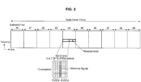
- FIG. 3 is an explanatory view showing an example of the frame format of an uplink signal in the frequency division multiplexing (FDD) LTE scheme.
- FDD frequency division multiplexing
- Physical channels and signals of uplink transmitted by a terminal of the LTE scheme to a base station include a physical up shared channel (PUSCH), transmission of a hybrid ARQ acknowledgment to indicate whether to retransmit a downlink transport block, a resource request for uplink data transmission, a physical up control channel (PUCCH) used to report channel conditions and the like of downlink, a physical random access channel (PRACH) used for random access, and an uplink reference signal (DRS) used by the base station to perform synchronous detection.
- PUSCH physical up shared channel
- PUCCH physical up control channel
- PRACH physical random access channel
- DRS uplink reference signal
- the resource allocation (scheduling information) of uplink to each terminal is notified by the physical down control channel (PDCCH) of the subframe four subframes before the allocated resource.
- the scheduling information contains, in addition to the position of the allocated resource block, frequency hopping information of uplink, the modulation and coding method, new data display used to clear a buffer by initial transmission, and transmission power control bits for the physical up shared channel (PUSCH).
- the scheduling information uses the terminal ID to perform a cyclic redundancy check (CRC) operation and the terminal can decode only scheduling information needed for the terminal without decoding scheduling information addressed to other terminals by decoding only information whose CRC checking is successful using the terminal ID of the terminal.
- CRC cyclic redundancy check
- a reference signal (DRS) provided with a reference signal sequence that is different from cell to cell and a phase rotation that is different from terminal to terminal is transmitted by using the fourth symbol of each slot.
- the service area of a femtocell overlaps with that of a macrocell.
- the femtocell has a mechanism to limit users (terminals) allowed to use and thus, interference is an important problem and interference avoidance between a femtocell and a macrocell operated at the same frequency is required.
- FIG. 4 is an explanatory view showing a state in which uplink interference from a macrocell terminal to a femtocell occurs.
- the interference adjustment method of the LTE scheme is proposed in 3GPP TR 36.921 .
- As an interference adjustment method of a downlink control channel a timing shift of the symbol level of the control channel is proposed.
- As an interference adjustment method of a downlink data channel methods of frequency reuse and transmission power control of a femtocell are proposed.
- As an interference adjustment method of an uplink control channel an allocation method in the frequency domain is proposed.
- As an interference adjustment method of an uplink data channel a transmission power control method of a femtocell terminal is proposed.
- the above interference adjustment methods are all methods of attempting to reduce interference with a macrocell or macrocell terminal.
- a macrocell terminal away from a macrocell is located near a femtocell and the macrocell terminal has no access rights to the femtocell
- the macrocell terminal needs large uplink transmission power to allow an uplink transmission wave to reach the distant macrocell and the uplink transmission wave of the macrocell terminal excessively interferes with uplink reception by the nearby femtocell so that deterioration of uplink throughput of the femtocell terminal, interruption of communication and the like could be caused.
- No effective means for reducing interference with a femtocell or a femtocell terminal in uplink of such data communication has been known.
- FIG. 5 is an explanatory view showing transmission data of a terminal with an uplink transport block in the frequency division multiplexing (FDD) LTE scheme and a timing example of a hybrid ARQ acknowledgment notifying the terminal from a base station through downlink whether to retransmit the transport block of the terminal.
- FDD frequency division multiplexing
- scheduling information of the uplink is transmitted to the terminal by the physical down control channel (PDCCH) transmitting downlink control information using the n-th subframe and the terminal receives the data in the same subframe n after a transmission delay Tp. Because there is the same transmission delay between terminal transmission and base station reception, there is a shift of 2*Tp between a transmission subframe and a reception subframe of the terminal.
- PDCCH physical down control channel
- the physical up shared channel (PUSCH) carrying uplink transport blocks is permitted for the subframe four subframes after the subframe by which scheduling information is transmitted.
- the terminal transmits transport block data to the base station by the (n + 4)-th subframe using PUSCH and the base station receives the data through the (n + 4)-th subframe.
- the base station transmits a hybrid ARQ acknowledgement to the terminal by the (n + 8)-th subframe of downlink using the physical hybrid ARQ information channel (PHICH). If a negative acknowledgement (NAK) is transmitted, the (n + 12)-th subframe four subframes thereafter is used for retransmission.
- the resource block used for retransmission is, if not explicitly specified by PDCCH, the same as that used for the initial transmission. In the uplink, therefore, the subframes used for retransmission are known in advance and the same resource block is used.
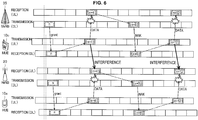
- FIG. 6 is an explanatory view showing an example of uplink interference between a macrocell and a femtocell in the frequency division multiplexing (FDD) LTE scheme.
- FDD frequency division multiplexing
- a femtocell base station capable of, when a terminal serviced by a base station other than a femtocell is located near the femtocell and the terminal has no access rights to the femtocell, preventing an uplink transmission wave of the terminal from interfering with uplink reception by the femtocell and easily preventing deterioration of uplink throughput of a femtocell terminal, interruption of communication and the like will be described.
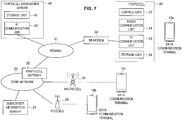
- FIG. 7 is an explanatory view showing an overall configuration of a data communication system according to an embodiment of the present disclosure.
- an overall configuration of the data communication system according to an embodiment of the present disclosure will be described using FIG. 7 .
- a data communication system 1 shown in FIG. 7 is a data communication system including a femtocell.
- the data communication system 1 includes data communication terminals 10a, 10b, 10c, the femtocell (indoor small base station) 20, an Internet 31, a femtocell gateway 32, a core network 33, a BB line modem 34, the macrocell (outdoor base station) 35, a picocell 36, a subscriber information server 37, and a femtocell management server 40.
- the macrocell (outdoor base station) 35 is a base station that covers a relatively wide range of the radius of a few hundred meters to a few tens of kilometers.
- the femtocell (indoor small base station) 20 is a base station of low transmission power whose cell radius is a few tens of meters.
- the femtocell 20 can be used by being installed indoors where a radio wave of the macrocell is hardly received.
- the femtocell 20 is connected to the core network 33 via, for example, the BB line modem 34, a BB line, the Internet 31, and the femtocell gateway 32.
- the communication interface between the femtocell 20 and the femtocell gateway 32 is defined by a standard interface, for example, Iuh (3GPP TS 25.467).
- the femtocell 20 includes a radio communication unit 24 that performs radio communication the data communication terminal 10a, an IP communication unit 25 that performs wire communication with the femtocell management server 40 or the femtocell gateway 32, the control unit 22 that exercises frequency switching control of the radio communication unit to measure downlink radio waves of surrounding base stations and measurement control of the reference signal, and a storage unit 26 that stores the address of the femtocell management server 40, the address of the femtocell gateway 32, ID (Allowed CSG List) of terminals allowed to access the femtocell 20. Radio parameters of the femtocell 20 such as the carrier frequency and maximum transmission power are also stored in the storage unit 26.
- the femtocell management server 40 is a server used for startup preparations and maintenance of a femtocell handled by one operator and includes an IP communication unit 42 that performs communication with a plurality of femtocells and a storage unit 41.
- the physical cell ID, carrier frequency, neighboring cell information, position information and the like used by femtocells managed by the femtocell management server 40 are stored in the storage unit 41.
- FIG. 7 shows only the one femtocell management server 40 operated by some operator (for example, Operator A), but other operators also operate similar servers.
- Operator A for example, Operator A
- femtocells managed by a plurality of operators may be managed by one femtocell management server.
- the femtocell 20 operated by Operator A is connected to the core network 33 via the femtocell gateway 32.
- the macrocell 35 is a macrocell operated by Operator A
- the picocell 36 is a picocell operated by Operator A.
- Operator A operates a downlink carrier frequency A and the macrocell 35, the picocell 36, and the femtocell 20 transmit the carrier frequency A in the downlink.
- the data communication terminals 10a, 10b, 10c are all terminals under contract with Operator A operating the core network 33, the data communication terminal 10a is located indoors where the femtocell 20 can be used, the data communication terminal 10b performs communication via the picocell 36, and the data communication terminal 10c performs communication via the macrocell 35.
- a downlink signal transmitted by the macrocell 35 is interference noise for the data communication terminal 10b.
- interference adjustments are made between the macrocell 35 and the picocell 36 and the picocell 36 is notified of information of ABS used by the macrocell 35.
- the picocell 36 transmits an important downlink signal to the data communication terminal 10b by allocating to a downlink subframe of the picocell 36 corresponding to the time of the subframe specified as ABS in the macrocell 35.
- the femtocell 20 When the femtocell 20 is turned on, the femtocell 20 searches radio waves of surrounding base stations including the macrocell 35 and measures reception power to receive and acquire broadcasting information. The femtocell 20 also connects to the femtocell management server 40 to acquire information about base stations positioned around the position information registered in advance and checks the position against measurement results by the femtocell 20 to select optimum radio parameters that do not overlap with those used by surrounding base stations.
- a downlink signal transmitted by the femtocell 20 is interference noise for the data communication terminal 10c and the femtocell periodically decides the maximum transmission power of the femtocell such that interference is minimized according to measurement results of intensity of reference signals from surrounding base stations.
- FIG. 8 is an explanatory view showing the configuration of the control unit 22 contained in the femtocell 20 according to an embodiment of the present disclosure.
- the configuration of the control unit 22 contained in the femtocell 20 according to an embodiment of the present disclosure will be described using FIG. 8 .
- the control unit 22 includes a terminal detection unit 51 and a resource allocation unit 52.
- the terminal detection unit 51 detects an uplink signal of the data communication terminal 10c serviced by the macrocell 35 as another base station.
- the resource allocation unit 52 allocates radio resources to the data communication terminal 10a serviced by the femtocell 20 using allocation priorities of radio resources stored in the storage unit 26.
- the resource allocation unit 52 preferentially allocates a radio resource of uplink or downlink of a high allocation priority to the data communication terminal 10a while lowering an allocation priority to the radio resource estimated to be used next by the data communication terminal 10c for uplink or downlink.
- control unit 22 contained in the femtocell 20 according to an embodiment of the present disclosure has been described using FIG. 8 .
- the control unit 22 can have the function configuration as shown in FIG. 8 by, for example, a computer program stored in the storage unit 26 being read and executed by the control unit 22.
- a reference signal sequence that is different from cell to cell is used as a decoding reference signal (DRS) of uplink arranged as the fourth symbol of PUSCH and a phase rotation that is different from terminal to terminal is provided to recognize each terminal.
- the femtocell 20 can detect the data communication terminal 10c as a macrocell terminal by detecting the intensity of an uplink signal containing DRS using a reference signal sequence other than the reference signal sequence used by the femtocell 20.
- uplink resources are allocated to the data communication terminal 10a as a femtocell terminal as described below.
- uplink resources are allocated to the data communication terminal 10a by a method by which a lower allocation priority is given to uplink resources of the data communication terminal 10a as a femtocell terminal in the subframe eight subframes after the detected subframe.
- FIG. 9 is an explanatory view showing an example of the resource allocation method of uplink of the femtocell 20 according to an embodiment of the present disclosure.
- the data communication terminal 10c as a macrocell terminal obtains permission of uplink allocation in the n-th subframe from the macrocell 35 and transmits a transport block by the (n + 4)-th subframe.
- the data communication terminal 10c is away from the macrocell 35 and if the femtocell 20 is closer, radio interference becomes worse and the frequency with which data retransmission is requested from the macrocell 35 is expected to be high.
- a negative acknowledgement (NAK) as a hybrid ARQ acknowledgement is transmitted by the (+8)-th subframe from the macrocell 35 to the data communication terminal 10c and the data communication terminal 10c transmits retransmission data by the (n + 12)-th subframe of uplink.
- the femtocell 20 When uplink transmission is requested from the data communication terminal 10a as a femtocell terminal, the femtocell 20 permits resource allocation of uplink in the (n + 5)-th subframe and the data communication terminal 10a transmits by the (n + 9)-th subframe. This is because the femtocell 20 does not detect an uplink of the data communication terminal 10a in the (n + 1)-th subframe and allocation priorities are not low.
- the femtocell 20 When the femtocell 20 detects an uplink of the data communication terminal 10c as a macrocell terminal in the (n + 4)-th subframe, the femtocell 20 lowers an allocation priority of the data communication terminal 10a in the (n + 8)-th subframe so that allocation permission of uplink is not granted to prevent uplink allocation to the data communication terminal 10a as a femtocell terminal in the (n + 12)-th subframe.
- the femtocell 20 allocates uplink resources of the data communication terminal 10a as a femtocell terminal, resources of the subframe, which are four subframes before, in which an uplink of the data communication terminal 10c as a macrocell terminal is not detected are preferentially allocated.
- the femtocell 20 may allocate, among a plurality of resource blocks in the subframes, resource blocks other than resource blocks used for uplink transmission of the macrocell.
- the femtocell 20 can probabilistically reduce interference by a method of still lowering allocation priorities of the same resource blocks as those in which uplink transmission of the data communication terminal 10c is detected.
- lower throughput of the macrocell 35 and the femtocell 20 can be caused by the same interference mechanism as that in the uplink.
- FIG. 10 is an explanatory view showing transmission data of a base station with a downlink transport block in the frequency division multiplexing (FDD) LTE scheme and a timing example of a hybrid ARQ acknowledgment notifying the base station through uplink whether to retransmit the transport block of the base station.
- FDD frequency division multiplexing
- Scheduling information of the downlink from the femtocell 20 or the macrocell 35 is transmitted to the data communication terminal 10a as a femtocell terminal or the data communication terminal 10c as a macrocell terminal by the physical down control channel (PDCCH) transmitting downlink control information using the n-th subframe and the data communication terminals 10a, 10c receive the data in the same n-th subframe after a transmission delay Tp.
- PDCCH physical down control channel
- the physical down shared channel (PDSCH) carrying downlink transport blocks is transmitted to the terminals by the same subframe as the subframe by which scheduling information is transmitted and each of the data communication terminals 10a, 10c receives PDSCH in the n-th subframe.
- PDSCH physical down shared channel
- Each of the data communication terminals 10a, 10c transmits a hybrid ARQ acknowledgement to the femtocell 20 or the macrocell 35 by the (n + 4)-th subframe of uplink using the physical up shared channel (PUSCH) or the physical up control channel (PUCCH).
- the femtocell 20 or the macrocell 35 can retransmit downlink data by the (n + 8)-th subframe if necessary.
- Retransmission data is in principle scheduled to be retransmitted in the same manner as the initial transmission, but like the initial data, the retransmission data can also be changed in arrangement on the frequency axis or transmission form according to scheduling information.
- FIG. 11 is an explanatory view showing an example of downlink interference between the macrocell 35 and the femtocell 20 in the frequency division multiplexing (FDD) LTE scheme. If the data communication terminal 10c as a macrocell terminal away from the macrocell 35 is located near the femtocell 20 and the data communication terminal 10c has no access rights to the femtocell 20, the reception level of a downlink signal of the femtocell 20 is expected to be high when compared with the reception level of a downlink signal of the macrocell 35 in the data communication terminal 10c.
- FDD frequency division multiplexing
- the downlink of the femtocell 20 excessively interferes with the downlink of the macrocell 35, causing retransmission of downlink data of the macrocell 35.
- a hybrid ARQ acknowledgement transmitted by the data communication terminal 10c as a macrocell terminal and that transmitted by the data communication terminal 10a are transmitted by the same subframe and because transmission power of the uplink of the data communication terminal 10c is high, the uplink of the femtocell 20 is excessively interfered with and the data communication terminal 10c inhibits the femtocell 20 from receiving a hybrid ARQ acknowledgement transmitted by the data communication terminal 10a, causing retransmission of downlink data of the femtocell 20.
- Such a state could mutually cause the macrocell 35 and the femtocell 20 to retransmit, leading to lower throughput of both of the data communication terminal 10a and the data communication terminal 10c.
- An interference adjustment method by the femtocell 20 to prevent such a state from arising will be described.
- the femtocell 20 in the LTE scheme detects an uplink of the data communication terminal 10c as a macrocell terminal and the uplink is a hybrid ARQ acknowledgement, the femtocell 20 lowers an allocation priority of femtocell terminal downlink resources in the subframe four subframes after the detected subframe.
- FIG. 12 is an explanatory view showing an example of the resource allocation method of downlink of the femtocell 20. It is assumed that the macrocell 35 transmits a downlink transport block to the data communication terminal 10c as a macrocell terminal by the n-th subframe.
- the data communication terminal 10c is away from the macrocell 35 and close to the femtocell 20 and thus, radio interference becomes worse and the frequency with which data retransmission is requested is expected to be high.
- a negative acknowledgement (NAK) as a hybrid ARQ acknowledgement is transmitted by the (n + 4)-th subframe from the data communication terminal 10c to the macrocell 35 and the macrocell 35 transmits retransmission data by the (n + 8)-th subframe of downlink.
- the femtocell 20 transmits a transport block to the data communication terminal 10a as a femtocell terminal by the (n + 6)-th subframe. This is because the femtocell 20 does not detect an uplink of the data communication terminal 10c as a macrocell terminal in the (n + 2)-th subframe and allocation priorities are not low.
- the femtocell 20 detects an uplink of the data communication terminal 10c in the (n + 4)-th subframe and finds that the uplink is a hybrid ARQ acknowledgement, the femtocell 20 lowers an allocation priority of the downlink in the (n + 8)-th subframe to prevent downlink allocation.
- the femtocell 20 allocates downlink resources of the data communication terminal 10a as a femtocell terminal, resources of the subframe, which are four subframes before, in which an uplink of the data communication terminal 10c as a macrocell terminal is not detected are preferentially allocated. Further, the femtocell 20 may decide allocation priorities after decoding the uplink signal to determine whether the uplink signal is a hybrid ARQ acknowledgment.
- the femtocell 20 may make interference adjustments based on detection of control information (PDCCH, PHICH) of the macrocell 35.
- control information PDCCH, PHICH
- the femtocell 20 can reliably know subframes and resource blocks used for uplink of the data communication terminal 10c as a macrocell terminal by detecting scheduling information of the uplink to the data communication terminal 10c as a macrocell terminal on PDCCH of the macrocell 35 a hybrid ARQ acknowledgement to the data communication terminal 10c on PHICH of the macrocell 35.
- the femtocell 20 can reliably know subframes and resource blocks used for downlink of the data communication terminal 10c by detecting scheduling information of the downlink to the data communication terminal 10c as a macrocell terminal on PDCCH of the macrocell 35.
- Detection of scheduling information of the uplink and downlink to the data communication terminal 10c on PDCCH of the macrocell 35 and a hybrid ARQ acknowledgement to the data communication terminal 10c on PHICH by the femtocell 20 is enabled by using, for example, a timing shift of control channels of the macrocell and femtocell as a conventional technology, a temporary stop of downlink transmission of the femtocell in the macrocell control region, and a detection method of the macrocell terminal ID.
- FIG. 13 is an explanatory view showing an example of a timing shift of control channels between the macrocell 35 and the femtocell 20.
- 3GPP TR 36.921 proposes a timing shift of the symbol level of control channels shown in FIG. 13 and a temporary stop of downlink transmission of the femtocell in the macrocell control region (PDCCH region).
- the femtocell 20 can execute the detection method of the macrocell terminal ID as described below. By temporarily stopping downlink transmission of the femtocell 20 in the macrocell control region (PDCCH region), the femtocell 20 can receive PDCCH and PHICH of the macrocell 35.
- PDCCH region the macrocell control region
- the femtocell 20 in the LTE scheme has a function to store PDCCH information of four subframes received from the macrocell 35 and detects PUSCH of uplink of the data communication terminal 10c as a macrocell terminal, it becomes possible to extract scheduling information corresponding to the resource block of the detected PUSCH from PDCCH information four subframes before and to detect the terminal ID attached to allocation information thereof.
- FIG. 14 is an explanatory view showing a processing example of control information of PDCCH.
- the resource allocation (scheduling information) of uplink to a terminal is notified by the physical down control channel (PDCCH) of the subframe four subframes before the resource to be allocated.
- Control information containing the position of the resource block to be allocated, frequency hopping information of uplink, the modulation and coding method, new data display used to clear a buffer by initial transmission, and transmission power control bits for the physical up shared channel (PUSCH) is provided.
- the cyclic redundancy check (CRC) is added to the control information (steps S101a, 101b, 101c) and the terminal ID is included for the CRC operation. Accordingly, it becomes possible to decode only scheduling information needed for the terminal without decoding scheduling information addressed to other terminals by decoding only information whose CRC checking is successful using the terminal ID of the terminal.
- control information is encoded by convolutional code (steps S102a, 102b, 102c), the rate is adjusted matching the resource amount of PDCCH transmission (steps S103a, 103b, 103c), and a plurality of pieces of control information is multiplexed (step S104), scrambled by a cell and subframe specific scramble sequence (step S105), QPSK modulated (step S106), and mapped to resource elements (step S107).
- the terminal ID can be detected by extracting the corresponding scheduling information from PDCCH of the subframe four subframes before based on the position of the resource block used for PUSCH transmission of the macrocell terminal and reversely detecting the terminal ID with which CRC checking of the scheduling information is successful.
- the femtocell succeeds in detecting the terminal ID of a macrocell terminal located nearby, scheduling information of uplink and downlink of which the terminal notified thereafter from a macrocell can efficiently be decoded from PDCCH of the macrocell using the terminal ID detected by the femtocell so that resource blocks allocated to uplink and downlink of the femtocell terminal do not overlap with those allocated to the macrocell terminal.
- FIG. 15 is an explanatory view showing a configuration example of the radio communication unit 24 in the femtocell 20 according to an embodiment of the present disclosure.
- the radio communication unit 24 of the femtocell 20 in the frequency division multiplexing (FDD) LTE scheme includes an antenna 101, a duplexer 102, a downlink receiving antenna 103, a downlink receiving RF filter 104, a reception processing unit 110, a transmission processing unit 120, a baseband processing unit 130, a downlink receiving unit 140, a crystal oscillator 150, and a frequency synthesizer 160.
- FDD frequency division multiplexing
- the reception processing unit 110 includes a reception amplifier 111, a receiving RF filter 112, and an orthogonal demodulator 113.
- the transmission processing unit 120 includes an orthogonal modulator 121, a transmission variable gain amplifier 122, a transmitting RF filter 123, a transmission power amplifier 124, and an isolator 125.
- the downlink receiving unit 140 includes a reception amplifier 141, a downlink receiving RF filter 142, and an orthogonal demodulator 143.
- a signal received by the antenna 101 is sent to the reception processing unit 110 via the duplexer 102.
- the reception processing unit 110 amplifies the signal sent from the duplexer 102 by the reception amplifier 111 and performs predetermined filtering thereon by the receiving RF filter 112 before demodulating the signal by the orthogonal demodulator 113.
- the demodulated signal is sent to the baseband processing unit 130.
- a signal sent from the baseband processing unit 130 to the transmission processing unit 120 is modulated by the orthogonal modulator 121, amplified by the transmission variable gain amplifier 122 and, after predetermined filtering being performed thereon by the transmitting RF filter 123, amplified by the transmission power amplifier 124 before being sent to the duplexer 102 via the isolator 125 that prevents backflow of signals. Then, the signal sent to the duplexer 102 is transmitted from the antenna 101.
- the downlink receiving unit 140 to receive a downlink is used to appropriately set the downlink transmission power of the femtocell 20 by measuring downlink signal intensity of the macrocell 35 whose area overlaps with that of the femtocell 20 so that a downlink transmission wave of the femtocell 20 does not excessively interferes with the downlink of the macrocell 35.
- the downlink receiving unit 140 is also used to shift control channels of the macrocell 35 and the femtocell 20 to an appropriate symbol level as shown in FIG. 13 by detecting symbol timing of the downlink of the macrocell 35 and receiving system information of the macrocell.
- An uplink transmission wave of the data communication terminal 10c as a macrocell terminal using the same frequency band as the femtocell 20 is received, like an uplink transmission wave of the data communication terminal 10a as a femtocell terminal, by the reception processing unit 110 in FIG. 15 . Because the data communication terminal 10c, which is far away from the macrocell 35 and close to the femtocell 20, needs to increase uplink transmission power, the femtocell 20 can easily detect an uplink transmission wave of the data communication terminal 10c.
- FIG. 16 is a flow chart showing macrocell terminal detection processing of the femtocell 20.
- the storage unit 26 of the femtocell 20 stores cell IDs of neighboring macrocells and neighboring femtocells.
- the femtocell 20 can check whether the serviced base station is a neighboring macrocell from the reference signal sequence contained in the reference signal of the fourth symbol of the slot.
- the femtocell 20 determines whether transmission of the macrocell terminal is received (step S202). If transmission of the macrocell terminal is not detected, the femtocell 20 receives the next subframe.
- the femtocell 20 can determine whether the detected PUSCH signal is a hybrid ARQ acknowledgement (step S203). If the PUSCH signal is a hybrid ARQ acknowledgement, the femtocell 20 lowers an allocation priority of downlink scheduling of the subframe four subframes later (step S204) and if the PUSCH signal is not a hybrid ARQ acknowledgement, the femtocell 20 lowers allocation priorities to uplink scheduling of the subframe four subframes later (step S205). In this manner, the femtocell 20 stores allocation priorities for uplink and downlink subframes of four subframes from the current one.
- FIG. 17 is a flow chart showing downlink scheduling processing of the femtocell 20.
- the femtocell 20 determines whether downlink data to the data communication terminal 10a as a femtocell terminal has arisen (step S301) and if downlink data to the data communication terminal 10a has arisen, the femtocell 20 checks allocation priorities of four subframes of the next subframe and thereafter and if allocation priorities of the next subframe are not low, the subframe is allocated and if allocation priorities of the next subframe are low, another subframe is allocated (step S302).
- FIG. 18 is a flow chart showing uplink scheduling processing of the femtocell 20.
- the femtocell 20 determines whether any uplink resource request is transmitted from the data communication terminal 10a as a femtocell terminal to the femtocell 20 (step S401) and if an uplink resource request is transmitted from the data communication terminal 10a to the femtocell 20, the femtocell 20 checks allocation priorities of four subframes of the first subframe that can be allocated and thereafter and if allocation priorities of the first subframe are not low, the subframe is allocated and if allocation priorities of the first subframe are low, another subframe is allocated (step S402).
- the femtocell 20 can prevent deterioration of throughput of the femtocell terminal.
- the femtocell 20 can prevent an uplink transmission wave of the terminal from excessively interfering with reception of uplink of the femtocell and easily prevent deterioration of throughput of the femtocell terminal and interruption of communication.
- the femtocell 20 detects the presence of the data communication terminal 10c and allocates radio resources used for uplink transmission to the data communication terminal 10a so that radio resources used for uplink transmission of the data communication terminal 10c and radio resources used for uplink transmission of the data communication terminal 10a as a femtocell terminal do not overlap.
- the femtocell 20 can prevent throughput of the femtocell terminal from deteriorating.
- the femtocell 20 can prevent a downlink transmission wave of the femtocell 20 from excessively interfering with downlink reception of the terminal and prevent deterioration of throughput of terminals of other base stations and interruption of communication.
- the femtocell 20 detects the terminal identifier (terminal ID) from uplink transmission of a macrocell terminal near the femtocell 20 and detects radio resources allocated to the macrocell terminal from the macrocell 35 so that interference between the femtocell 20 and the macrocell 35 can be reduced by allocating radio resources to the femtocell terminal in such a way that radio resources used by the femtocell terminal do not overlap.
- terminal ID terminal identifier
- the operation of the femtocell 20 may be implemented by hardware or by software.
- a computer program may be stored inside the femtocell 20 so that the computer program is read and executed by a CPU or a control apparatus provided inside the femtocell 20.
- the resource allocation unit 52 may change allocation priorities in accordance with intensity of the uplink signal such as lowering an allocation priority of radio resources used by the terminal having transmitted the strongest uplink signal. This is because the terminal having transmitted the strongest uplink signal is considered to be positioned near the femtocell 20 and collisions can be avoided by allocating such radio resources less frequently.
- the resource allocation unit 52 may change allocation priorities in accordance with the number of times of detecting an uplink signal from each terminal such as lowering allocation priorities of radio resources used by the terminal.
- the present technology can also adopt configurations as described below:
Landscapes
- Engineering & Computer Science (AREA)
- Computer Networks & Wireless Communication (AREA)
- Signal Processing (AREA)
- Mobile Radio Communication Systems (AREA)
Claims (15)
- Funkbasisstation, die Folgendes umfasst:eine Endgerätdetektionseinheit (51), die konfiguriert ist, um ein Uplink-Signal eines ersten Endgeräts, das von einer anderen Basisstation bedient wird, zu detektieren;eine Speichereinheit (41), die konfiguriert ist, um eine Zuteilungspriorität einer Funkressource eine vorher bestimmte Zeit lang zu speichern; undeine Ressourcenzuteilungseinheit (52), die konfiguriert ist, um einem zweiten Endgerät, das von der Funkbasisstation bedient wird, eine Funkressource unter Nutzung der in der Speichereinheit gespeicherten Zuteilungspriorität der Funkressource zuzuteilen,wobei die Ressourcenzuteilungseinheit (52), wenn die Endgerätdetektionseinheit (51) das Uplink-Signal des ersten Endgeräts detektiert, konfiguriert ist, um dem zweiten Endgerät eine Funkressource eines Uplinks mit einer hohen Zuteilungspriorität zuzuteilen, während sie eine Zuteilungspriorität einer Funkressource, die gemäß einer Schätzung als Nächstes durch das erste Endgerät für den Uplink genutzt wird, herabstuft.
- Funkbasisstation nach Anspruch 1, wobei die Ressourcenzuteilungseinheit konfiguriert ist, um eine Priorität einer Funkressource, die gemäß einer Schätzung zu einer Übertragung von Neuübertragungsdaten von Uplink-Daten, die durch das erste Endgerät übertragen werden, genutzt wird, herabzustufen.
- Funkbasisstation nach Anspruch 1, wobei die Ressourcenzuteilungseinheit, wenn die Endgerätdetektionseinheit die Uplink-Signale von mehreren der ersten Endgeräte detektiert, konfiguriert ist, um die Zuteilungspriorität entsprechend der Intensität der Uplink-Signale zu ändern.
- Funkbasisstation nach Anspruch 3, wobei die Ressourcenzuteilungseinheit, wenn die Endgerätdetektionseinheit die Uplink-Signale von mehreren der ersten Endgeräte detektiert, konfiguriert ist, um eine Zuteilungspriorität einer Funkressource, die vom ersten Endgerät, das das stärkste Uplink-Signal übertragen hat, genutzt wird, herabzustufen.
- Funkbasisstation nach Anspruch 1, wobei die Ressourcenzuteilungseinheit, wenn die Uplink-Signale von den ersten Endgeräten mehrere Male detektiert werden, konfiguriert ist, um die Zuteilungspriorität in Übereinstimmung damit, wie viele Male die Uplink-Signale pro Endgerät detektiert wurden, zu ändern.
- Funkbasisstation nach Anspruch 5, wobei die Ressourcenzuteilungseinheit, wenn die Uplink-Signale von den ersten Endgeräten mehrere Male detektiert werden, konfiguriert ist, um die Zuteilungspriorität für die Funkressource, die gemäß einer Schätzung als Nächstes durch das erste Endgerät für den Uplink genutzt wird, herabzustufen.
- Funkbasisstation nach Anspruch 1, die ferner Folgendes umfasst:eine Downlink-Empfangseinheit, die konfiguriert ist, um ein Downlink-Signal von der anderen Basisstation zu empfangen,wobei die Speichereinheit konfiguriert ist, um durch die Downlink-Empfangseinheit empfangene Zuteilungsinformationen zu einer Funkressource der anderen Basisstation zu empfangen und eine vorher bestimmte Zeit lang zu speichern, undwobei die Ressourcenzuteilungseinheit, wenn die Endgerätdetektionseinheit das Uplink-Signal des ersten Endgeräts detektiert, konfiguriert ist, um eine ID des ersten Endgeräts aus den in der Speichereinheit gespeicherten und durch die Downlink-Empfangseinheit empfangenen Zuteilungsinformationen zur Funkressource zu bestimmen.
- Funkbasisstation nach Anspruch 7, wobei die Ressourcenzuteilungseinheit konfiguriert ist, um Funkressourcen des Uplinks und eines Downlinks, die dem ersten Endgerät zugeteilt sind, aus der ID des ersten Endgeräts und den Zuteilungsinformationen zur Funkressource der anderen Basisstation zu detektieren, Zuteilungsprioritäten der Funkressourcen, die dem ersten Endgerät zugeteilt sind, herabstuft und die Funkressource mit der höheren Zuteilungspriorität dem zweiten Endgerät, das von der Funkbasisstation bedient wird, zuteilt.
- Funkbasisstation, die Folgendes umfasst:eine Endgerätdetektionseinheit (51), die konfiguriert ist, um ein Uplink-Signal eines ersten Endgeräts, das von einer anderen Basisstation bedient wird, zu detektieren;eine Speichereinheit (41), die konfiguriert ist, um eine Zuteilungspriorität einer Funkressource eine vorher bestimmte Zeit lang zu speichern; undeine Ressourcenzuteilungseinheit (52), die konfiguriert ist, um einem zweiten Endgerät, das von der Funkbasisstation bedient wird, eine Funkressource unter Nutzung der in der Speichereinheit gespeicherten Zuteilungspriorität der Funkressource zuzuteilen,wobei die Ressourcenzuteilungseinheit (52), wenn die Endgerätdetektionseinheit (51) das Uplink-Signal des ersten Endgeräts detektiert, konfiguriert ist, um dem zweiten Endgerät eine Funkressource eines Downlinks mit einer hohen Zuteilungspriorität zuzuteilen, während sie eine Zuteilungspriorität einer Funkressource, die gemäß einer Schätzung als Nächstes durch das erste Endgerät für den Downlink genutzt wird, herabstuft.
- Funkbasisstation nach Anspruch 9, wobei die Ressourcenzuteilungseinheit konfiguriert ist, um eine Zuteilungspriorität einer Funkressource, die gemäß einer Schätzung zu einer Übertragung von Neuübertragungsdaten von der anderen Basisstation an die erste Station in Ansprechen auf eine Neuübertragungsanforderung vom ersten Endgerät an die andere Basisstation genutzt wird, herabzustufen.
- Funkbasisstation nach Anspruch 9, wobei die Ressourcenzuteilungseinheit, wenn die Endgerätdetektionseinheit das Uplink-Signal des ersten Endgeräts detektiert, konfiguriert ist, um zu bestimmen, ob das Uplink-Signal ein Neuübertragungsanforderungssignal ist, und die Ressourcenzuteilungseinheit, wenn das Uplink-Signal das Neuübertragungsanforderungssignal ist, konfiguriert ist, um die Zuteilungspriorität der Funkressource, die gemäß einer Schätzung als Nächstes durch das erste Endgerät für den Downlink genutzt wird, herabzustufen.
- Kommunikationssteuerungsverfahren einer Funkbasisstation, wobei das Kommunikationssteuerungsverfahren Folgendes umfasst:Detektieren eines Uplink-Signals eines ersten Endgeräts, das von einer anderen Basisstation bedient wird;Speichern einer Zuteilungspriorität einer Funkressource eine vorher bestimmte Zeit lang; undZuteilen einer Funkressource zu einem zweiten Endgerät, das von einer Basisstation bedient wird, unter Nutzung der gespeicherten Zuteilungspriorität der Funkressource,wenn das Uplink-Signal des ersten Endgeräts detektiert wird, Zuteilen der Funkressource eines Uplinks mit einer hohen Zuteilungspriorität zum zweiten Endgerät während eines Herabstufens einer Zuteilungspriorität einer Funkressource, die gemäß einer Schätzung als Nächstes durch das erste Endgerät für den Uplink genutzt wird.
- Kommunikationssteuerungsverfahren einer Funkbasisstation, das Folgendes umfasst:Detektieren eines Uplink-Signals eines ersten Endgeräts, das von einer anderen Basisstation bedient wird;Speichern einer Zuteilungspriorität einer Funkressource eine vorher bestimmte Zeit lang; undZuteilen einer Funkressource zu einem zweiten Endgerät, das von einer Funkbasisstation bedient wird, unter Nutzung der gespeicherten Zuteilungspriorität der Funkressource,wenn das Uplink-Signal des ersten Endgeräts detektiert wird, Zuteilen der Funkressource eines Downlinks mit einer hohen Zuteilungspriorität zum zweiten Endgerät während eines Herabstufens einer Zuteilungspriorität einer Funkressource, die gemäß einer Schätzung als Nächstes durch das erste Endgerät für den Downlink genutzt wird.
- Computerprogramm, das bewirkt, dass ein Computer Folgendes ausführt:Detektieren eines Uplink-Signals eines ersten Endgeräts, das von einer anderen Basisstation bedient wird;Speichern einer Zuteilungspriorität einer Funkressource eine vorher bestimmte Zeit lang; undZuteilen einer Funkressource zu einem zweiten Endgerät, das von einer Funkbasisstation bedient wird, unter Nutzung der gespeicherten Zuteilungspriorität der Funkressource,wenn das Uplink-Signal des ersten Endgeräts detektiert wird, Zuteilen der Funkressource eines Uplinks mit einer hohen Zuteilungspriorität zum zweiten Endgerät während eines Herabstufens einer Zuteilungspriorität einer Funkressource, die gemäß einer Schätzung als Nächstes durch das erste Endgerät für den Uplink genutzt wird.
- Computerprogramm, das bewirkt, dass ein Computer Folgendes ausführt:Detektieren eines Uplink-Signals eines ersten Endgeräts, das von einer anderen Basisstation bedient wird;Speichern einer Zuteilungspriorität einer Funkressource eine vorher bestimmte Zeit lang; undZuteilen einer Funkressource zu einem zweiten Endgerät, das von einer Funkbasisstation bedient wird, unter Nutzung der gespeicherten Zuteilungspriorität der gespeicherten Funkressource,wenn das Uplink-Signal des ersten Endgeräts detektiert wird, Zuteilen der Funkressource eines Downlinks mit einer hohen Zuteilungspriorität zum zweiten Endgerät während eines Herabstufens einer Zuteilungspriorität einer Funkressource, die gemäß einer Schätzung als Nächstes durch das erste Endgerät für den Downlink genutzt wird.
Applications Claiming Priority (2)
| Application Number | Priority Date | Filing Date | Title |
|---|---|---|---|
| JP2011267636 | 2011-12-07 | ||
| PCT/JP2012/079791 WO2013084694A1 (ja) | 2011-12-07 | 2012-11-16 | 無線基地局、無線基地局の通信制御方法及びコンピュータプログラム |
Publications (3)
| Publication Number | Publication Date |
|---|---|
| EP2790432A1 EP2790432A1 (de) | 2014-10-15 |
| EP2790432A4 EP2790432A4 (de) | 2015-07-22 |
| EP2790432B1 true EP2790432B1 (de) | 2019-03-06 |
Family
ID=48574072
Family Applications (1)
| Application Number | Title | Priority Date | Filing Date |
|---|---|---|---|
| EP12856415.0A Not-in-force EP2790432B1 (de) | 2011-12-07 | 2012-11-16 | Drahtlose basisstation, kommunikationssteuerungsverfahren für die drahtlose basisstation und computerprogramm |
Country Status (16)
| Country | Link |
|---|---|
| US (1) | US9332562B2 (de) |
| EP (1) | EP2790432B1 (de) |
| JP (1) | JP5892176B2 (de) |
| CN (1) | CN103959836B (de) |
| AU (1) | AU2012349663B2 (de) |
| BR (1) | BR112014013238A2 (de) |
| CA (1) | CA2851088A1 (de) |
| IL (1) | IL232653A0 (de) |
| IN (1) | IN2014CN04072A (de) |
| MX (1) | MX2014006519A (de) |
| PH (1) | PH12014501225A1 (de) |
| RU (1) | RU2014122155A (de) |
| SG (1) | SG11201401132UA (de) |
| TR (1) | TR201904762T4 (de) |
| WO (1) | WO2013084694A1 (de) |
| ZA (1) | ZA201403498B (de) |
Families Citing this family (24)
| Publication number | Priority date | Publication date | Assignee | Title |
|---|---|---|---|---|
| CN104285488B (zh) | 2012-05-10 | 2018-12-14 | 索尼公司 | 通信控制装置、通信控制方法以及终端装置 |
| EP3618556A1 (de) | 2012-07-05 | 2020-03-04 | Sony Corporation | Kommunikationssteuerungsvorrichtung, kommunikationssteuerungsverfahren, programm, endgerät und kommunikationssteuerungssystem |
| EP2884789B1 (de) | 2012-08-13 | 2021-05-19 | Sony Corporation | Kommunikationssteuerungsvorrichtung, endgerät und kommunikationssteuerungsverfahren |
| US9998985B2 (en) | 2012-08-31 | 2018-06-12 | Sony Corporation | Communication control apparatus, terminal apparatus, communication control method, program, and communication control system |
| CN105309020B (zh) * | 2013-06-21 | 2019-08-20 | 富士通株式会社 | 发送装置、接收装置、发送方法以及接收方法 |
| JP2015056744A (ja) * | 2013-09-11 | 2015-03-23 | シャープ株式会社 | 移動体通信端末 |
| EP3032902B1 (de) | 2013-09-12 | 2021-09-01 | Huawei Technologies Co., Ltd. | Verfahren zur gewinnung von informationen, endgerät, basisstation und system |
| CN104519533A (zh) * | 2013-09-26 | 2015-04-15 | 中兴通讯股份有限公司 | 一种传输系统信息的方法、基站及终端 |
| EP3062452B1 (de) * | 2013-10-22 | 2019-12-04 | LG Electronics Inc. | Verfahren und vorrichtung zur übertragung eines physikalischen downlink-steuerkanals in einem drahtlosen zugangssystem mit unterstützung von maschinenkommunikation |
| CN104640210B (zh) * | 2013-11-15 | 2019-04-30 | 深圳市中兴微电子技术有限公司 | 一种基带数据存储控制方法和装置 |
| KR20180107321A (ko) | 2013-12-06 | 2018-10-01 | 후지쯔 가부시끼가이샤 | D2d 탐색 신호의 송신 방법, 장치 및 통신 시스템 |
| CN105122894A (zh) * | 2014-01-26 | 2015-12-02 | 华为技术有限公司 | 一种用户设备、基站及小区发现的方法 |
| US11582749B2 (en) * | 2014-07-03 | 2023-02-14 | Qualcomm Incorporated | Cell discovery in a wireless network using an unlicensed radio frequency spectrum band |
| KR102213905B1 (ko) | 2014-08-06 | 2021-02-10 | 인터디지탈 패튼 홀딩스, 인크 | 디바이스-대-디바이스(d2d) 선점 및 액세스 제어 |
| CN104242007B (zh) * | 2014-09-26 | 2016-05-18 | 中讯邮电咨询设计院有限公司 | 小型基站在非暴露环境下的隔离浮地防雷方法 |
| WO2016059960A1 (ja) * | 2014-10-17 | 2016-04-21 | ソニー株式会社 | 装置 |
| US11146376B2 (en) * | 2015-04-22 | 2021-10-12 | Qualcomm Incorporated | System type dependent master information block (MIB) |
| US10334617B2 (en) | 2015-06-16 | 2019-06-25 | Qualcomm Incorporated | System information for enhanced machine type communication |
| US9814056B2 (en) * | 2015-08-24 | 2017-11-07 | Qualcomm Incorporated | Methods and apparatus for interference management of wireless links with overriding link priority |
| US20180206210A1 (en) * | 2015-08-31 | 2018-07-19 | Sharp Kabushiki Kaisha | Communication device, communication processing method, and program |
| US10382971B2 (en) * | 2015-09-14 | 2019-08-13 | Telefonaktiebolaget Lm Ericsson (Publ) | Methods and devices for requesting and assigning resources in an unlicensed spectrum |
| CN109076509B (zh) * | 2016-05-13 | 2024-01-16 | 苹果公司 | 车辆近距离服务的优先通信 |
| US10257776B2 (en) * | 2016-09-14 | 2019-04-09 | Indian Institute Of Technology, Hyderabad | Method of performing cell search by user equipment (UE) |
| CN108282898B (zh) * | 2017-01-06 | 2023-10-24 | 华为技术有限公司 | 随机接入方法、用户设备和网络设备 |
Family Cites Families (18)
| Publication number | Priority date | Publication date | Assignee | Title |
|---|---|---|---|---|
| JPH09224283A (ja) | 1996-02-19 | 1997-08-26 | Mitsubishi Electric Corp | 移動通信装置のチャネル割当て方法 |
| EP1421710B1 (de) * | 2001-08-16 | 2017-11-15 | QUALCOMM Incorporated | Verfahren, Mobilkommunikationsgerät und Basisstation in einem Kommunikationssystem mit gemeinsamen Kommunikationsressourcen |
| JP3967115B2 (ja) * | 2001-11-22 | 2007-08-29 | 株式会社エヌ・ティ・ティ・ドコモ | 基地局、無線リソース制御装置、端末装置、通信システム及び通信方法 |
| EP1653758A4 (de) * | 2003-08-08 | 2010-04-28 | Mitsubishi Electric Corp | Kommunikationsendgerät und kommunikationssystem |
| KR101062674B1 (ko) * | 2006-02-18 | 2011-09-06 | 삼성전자주식회사 | 무선 통신 시스템에서 자원을 할당하고 통신을 수행하는 장치 및 방법 |
| JP4786382B2 (ja) * | 2006-03-27 | 2011-10-05 | 京セラ株式会社 | 基地局装置及びチャネル割り当て方法 |
| US7480271B2 (en) * | 2006-09-26 | 2009-01-20 | Cisco Technology, Inc. | Method for reducing multi-cell interferences in wireless communications |
| KR101457688B1 (ko) * | 2007-10-04 | 2014-11-12 | 엘지전자 주식회사 | 제어채널의 수신오류를 검출하는 데이터 전송방법 |
| JP5309708B2 (ja) * | 2008-06-16 | 2013-10-09 | 富士通株式会社 | 移動局及びデータ送信方法 |
| GB2461159B (en) * | 2008-06-18 | 2012-01-04 | Lg Electronics Inc | Method for transmitting Mac PDUs |
| US8391882B2 (en) | 2008-10-22 | 2013-03-05 | Qualcomm Incorporated | Method and system for interference management in a spectrum shared by WAN and femto cells |
| JP2010178237A (ja) * | 2009-02-02 | 2010-08-12 | Sharp Corp | 通信システム及び基地局装置、端末装置、および基地局装置、端末装置に実行させるプログラム |
| JP2011066874A (ja) | 2009-08-17 | 2011-03-31 | Sony Corp | 通信システム、通信装置及び通信方法、並びにコンピューター・プログラム |
| CN101917770B (zh) * | 2010-08-10 | 2013-02-20 | 北京邮电大学 | 一种家庭基站的干扰抑制方法 |
| JP4790861B2 (ja) | 2010-10-04 | 2011-10-12 | 京セラ株式会社 | 移動通信システム、基地局装置およびその制御方法 |
| GB2487757B (en) * | 2011-02-03 | 2015-11-04 | Nvidia Corp | Apparatus and method for reducing interference |
| CN102655676B (zh) * | 2011-03-01 | 2014-12-31 | 华为技术有限公司 | 子帧配置方法、数据处理方法及基站、用户设备 |
| WO2012147198A1 (ja) | 2011-04-28 | 2012-11-01 | 京セラ株式会社 | 基地局及び通信制御方法 |
-
2012
- 2012-11-16 EP EP12856415.0A patent/EP2790432B1/de not_active Not-in-force
- 2012-11-16 CN CN201280059318.6A patent/CN103959836B/zh not_active Expired - Fee Related
- 2012-11-16 CA CA2851088A patent/CA2851088A1/en not_active Abandoned
- 2012-11-16 AU AU2012349663A patent/AU2012349663B2/en not_active Ceased
- 2012-11-16 JP JP2013548166A patent/JP5892176B2/ja not_active Expired - Fee Related
- 2012-11-16 RU RU2014122155/07A patent/RU2014122155A/ru not_active Application Discontinuation
- 2012-11-16 US US14/358,279 patent/US9332562B2/en not_active Expired - Fee Related
- 2012-11-16 WO PCT/JP2012/079791 patent/WO2013084694A1/ja not_active Ceased
- 2012-11-16 TR TR2019/04762T patent/TR201904762T4/tr unknown
- 2012-11-16 BR BR112014013238A patent/BR112014013238A2/pt not_active Application Discontinuation
- 2012-11-16 MX MX2014006519A patent/MX2014006519A/es active IP Right Grant
- 2012-11-16 SG SG11201401132UA patent/SG11201401132UA/en unknown
-
2014
- 2014-05-14 ZA ZA2014/03498A patent/ZA201403498B/en unknown
- 2014-05-15 IL IL232653A patent/IL232653A0/en unknown
- 2014-05-30 PH PH12014501225A patent/PH12014501225A1/en unknown
- 2014-05-30 IN IN4072CHN2014 patent/IN2014CN04072A/en unknown
Non-Patent Citations (1)
| Title |
|---|
| None * |
Also Published As
| Publication number | Publication date |
|---|---|
| US20140302867A1 (en) | 2014-10-09 |
| BR112014013238A2 (pt) | 2017-06-13 |
| SG11201401132UA (en) | 2014-10-30 |
| AU2012349663B2 (en) | 2017-03-09 |
| ZA201403498B (en) | 2014-11-26 |
| MX2014006519A (es) | 2014-07-10 |
| TR201904762T4 (tr) | 2019-05-21 |
| IN2014CN04072A (de) | 2015-09-04 |
| RU2014122155A (ru) | 2015-12-10 |
| JPWO2013084694A1 (ja) | 2015-04-27 |
| AU2012349663A1 (en) | 2014-05-08 |
| IL232653A0 (en) | 2014-06-30 |
| WO2013084694A1 (ja) | 2013-06-13 |
| JP5892176B2 (ja) | 2016-03-23 |
| EP2790432A1 (de) | 2014-10-15 |
| US9332562B2 (en) | 2016-05-03 |
| CA2851088A1 (en) | 2013-06-13 |
| CN103959836A (zh) | 2014-07-30 |
| EP2790432A4 (de) | 2015-07-22 |
| CN103959836B (zh) | 2018-01-16 |
| PH12014501225A1 (en) | 2014-09-08 |
Similar Documents
| Publication | Publication Date | Title |
|---|---|---|
| EP2790432B1 (de) | Drahtlose basisstation, kommunikationssteuerungsverfahren für die drahtlose basisstation und computerprogramm | |
| US11963219B2 (en) | DMTC window reservation signal in NR shared spectrum | |
| US11888788B2 (en) | System type dependent master information block (MIB) | |
| US11064424B2 (en) | Shared spectrum synchronization design | |
| TWI753172B (zh) | 根據訊框結構的實體通道配置 | |
| US9949263B2 (en) | Frequency resource allocation for a narrow-band cellular internet of things system | |
| TWI781980B (zh) | 用於embb/urllc多工的當前指示通道 | |
| US8830928B2 (en) | Mobile communication method and radio base station | |
| EP3606194B1 (de) | Techniken zum senden und empfangen von synchronisierungssignalen über ein unlizenziertes funkfrequenzspektrumsband | |
| EP3386139B1 (de) | Übertragung und empfang von steuerdaten in einem kommunikationssystem | |
| US8879437B2 (en) | Backward compatible LTE system design for asymmetric uplink/downlink spectrum | |
| US11595983B2 (en) | Application of an uplink (UL) cancellation indication in a wireless communications network | |
| CN115136555B (zh) | 轻量版新无线电通信的物理广播信道增强 | |
| US20200092763A1 (en) | Multi-operator handover in new radio shared spectrum | |
| CN102726088B (zh) | 无线通信系统、基站装置、移动站装置以及通信控制方法 | |
| KR20180066066A (ko) | 향상된 컴포넌트 캐리어 발견 기준 신호들 | |
| KR20170048377A (ko) | Noma 다운링크 송신들의 세트에 대한 다운링크 제어 정보를 송신 및 수신하기 위한 기술들 | |
| AU2017237734A1 (en) | Improvements on co-channel sidelink LTE V2V and DSRC communication | |
| US9930539B2 (en) | Physical broadcast channel for coverage enhancement | |
| US20130225192A1 (en) | Base station device, communication system, management device, and methods relating to the same | |
| EP3539331B1 (de) | Netzwerkentdeckung und -synchronisierung für nr-ss | |
| US10517104B2 (en) | Interference management for networks with variable transmission time intervals | |
| US20210243643A1 (en) | Self-reportable radio link control status protocol data units |
Legal Events
| Date | Code | Title | Description |
|---|---|---|---|
| PUAI | Public reference made under article 153(3) epc to a published international application that has entered the european phase |
Free format text: ORIGINAL CODE: 0009012 |
|
| 17P | Request for examination filed |
Effective date: 20140624 |
|
| AK | Designated contracting states |
Kind code of ref document: A1 Designated state(s): AL AT BE BG CH CY CZ DE DK EE ES FI FR GB GR HR HU IE IS IT LI LT LU LV MC MK MT NL NO PL PT RO RS SE SI SK SM TR |
|
| DAX | Request for extension of the european patent (deleted) | ||
| RA4 | Supplementary search report drawn up and despatched (corrected) |
Effective date: 20150624 |
|
| RIC1 | Information provided on ipc code assigned before grant |
Ipc: H04W 72/10 20090101AFI20150618BHEP Ipc: H04W 84/04 20090101ALN20150618BHEP Ipc: H04W 16/16 20090101ALN20150618BHEP |
|
| STAA | Information on the status of an ep patent application or granted ep patent |
Free format text: STATUS: EXAMINATION IS IN PROGRESS |
|
| 17Q | First examination report despatched |
Effective date: 20170419 |
|
| REG | Reference to a national code |
Ref country code: DE Ref legal event code: R079 Ref document number: 602012057581 Country of ref document: DE Free format text: PREVIOUS MAIN CLASS: H04W0016160000 Ipc: H04W0072100000 |
|
| GRAP | Despatch of communication of intention to grant a patent |
Free format text: ORIGINAL CODE: EPIDOSNIGR1 |
|
| STAA | Information on the status of an ep patent application or granted ep patent |
Free format text: STATUS: GRANT OF PATENT IS INTENDED |
|
| RIC1 | Information provided on ipc code assigned before grant |
Ipc: H04W 84/04 20090101ALN20180828BHEP Ipc: H04W 72/10 20090101AFI20180828BHEP Ipc: H04W 16/16 20090101ALN20180828BHEP |
|
| INTG | Intention to grant announced |
Effective date: 20180914 |
|
| RIC1 | Information provided on ipc code assigned before grant |
Ipc: H04W 84/04 20090101ALN20180904BHEP Ipc: H04W 72/10 20090101AFI20180904BHEP Ipc: H04W 16/16 20090101ALN20180904BHEP |
|
| GRAJ | Information related to disapproval of communication of intention to grant by the applicant or resumption of examination proceedings by the epo deleted |
Free format text: ORIGINAL CODE: EPIDOSDIGR1 |
|
| STAA | Information on the status of an ep patent application or granted ep patent |
Free format text: STATUS: EXAMINATION IS IN PROGRESS |
|
| GRAS | Grant fee paid |
Free format text: ORIGINAL CODE: EPIDOSNIGR3 |
|
| STAA | Information on the status of an ep patent application or granted ep patent |
Free format text: STATUS: GRANT OF PATENT IS INTENDED |
|
| GRAA | (expected) grant |
Free format text: ORIGINAL CODE: 0009210 |
|
| STAA | Information on the status of an ep patent application or granted ep patent |
Free format text: STATUS: THE PATENT HAS BEEN GRANTED |
|
| INTC | Intention to grant announced (deleted) | ||
| AK | Designated contracting states |
Kind code of ref document: B1 Designated state(s): AL AT BE BG CH CY CZ DE DK EE ES FI FR GB GR HR HU IE IS IT LI LT LU LV MC MK MT NL NO PL PT RO RS SE SI SK SM TR |
|
| REG | Reference to a national code |
Ref country code: GB Ref legal event code: FG4D |
|
| REG | Reference to a national code |
Ref country code: CH Ref legal event code: EP Ref country code: AT Ref legal event code: REF Ref document number: 1106339 Country of ref document: AT Kind code of ref document: T Effective date: 20190315 |
|
| REG | Reference to a national code |
Ref country code: DE Ref legal event code: R096 Ref document number: 602012057581 Country of ref document: DE |
|
| REG | Reference to a national code |
Ref country code: IE Ref legal event code: FG4D |
|
| REG | Reference to a national code |
Ref country code: NL Ref legal event code: FP |
|
| REG | Reference to a national code |
Ref country code: LT Ref legal event code: MG4D |
|
| PG25 | Lapsed in a contracting state [announced via postgrant information from national office to epo] |
Ref country code: LT Free format text: LAPSE BECAUSE OF FAILURE TO SUBMIT A TRANSLATION OF THE DESCRIPTION OR TO PAY THE FEE WITHIN THE PRESCRIBED TIME-LIMIT Effective date: 20190306 Ref country code: FI Free format text: LAPSE BECAUSE OF FAILURE TO SUBMIT A TRANSLATION OF THE DESCRIPTION OR TO PAY THE FEE WITHIN THE PRESCRIBED TIME-LIMIT Effective date: 20190306 Ref country code: NO Free format text: LAPSE BECAUSE OF FAILURE TO SUBMIT A TRANSLATION OF THE DESCRIPTION OR TO PAY THE FEE WITHIN THE PRESCRIBED TIME-LIMIT Effective date: 20190606 Ref country code: SE Free format text: LAPSE BECAUSE OF FAILURE TO SUBMIT A TRANSLATION OF THE DESCRIPTION OR TO PAY THE FEE WITHIN THE PRESCRIBED TIME-LIMIT Effective date: 20190306 |
|
| PG25 | Lapsed in a contracting state [announced via postgrant information from national office to epo] |
Ref country code: GR Free format text: LAPSE BECAUSE OF FAILURE TO SUBMIT A TRANSLATION OF THE DESCRIPTION OR TO PAY THE FEE WITHIN THE PRESCRIBED TIME-LIMIT Effective date: 20190607 Ref country code: HR Free format text: LAPSE BECAUSE OF FAILURE TO SUBMIT A TRANSLATION OF THE DESCRIPTION OR TO PAY THE FEE WITHIN THE PRESCRIBED TIME-LIMIT Effective date: 20190306 Ref country code: BG Free format text: LAPSE BECAUSE OF FAILURE TO SUBMIT A TRANSLATION OF THE DESCRIPTION OR TO PAY THE FEE WITHIN THE PRESCRIBED TIME-LIMIT Effective date: 20190606 Ref country code: LV Free format text: LAPSE BECAUSE OF FAILURE TO SUBMIT A TRANSLATION OF THE DESCRIPTION OR TO PAY THE FEE WITHIN THE PRESCRIBED TIME-LIMIT Effective date: 20190306 Ref country code: RS Free format text: LAPSE BECAUSE OF FAILURE TO SUBMIT A TRANSLATION OF THE DESCRIPTION OR TO PAY THE FEE WITHIN THE PRESCRIBED TIME-LIMIT Effective date: 20190306 |
|
| REG | Reference to a national code |
Ref country code: AT Ref legal event code: MK05 Ref document number: 1106339 Country of ref document: AT Kind code of ref document: T Effective date: 20190306 |
|
| PG25 | Lapsed in a contracting state [announced via postgrant information from national office to epo] |
Ref country code: AL Free format text: LAPSE BECAUSE OF FAILURE TO SUBMIT A TRANSLATION OF THE DESCRIPTION OR TO PAY THE FEE WITHIN THE PRESCRIBED TIME-LIMIT Effective date: 20190306 Ref country code: ES Free format text: LAPSE BECAUSE OF FAILURE TO SUBMIT A TRANSLATION OF THE DESCRIPTION OR TO PAY THE FEE WITHIN THE PRESCRIBED TIME-LIMIT Effective date: 20190306 Ref country code: PT Free format text: LAPSE BECAUSE OF FAILURE TO SUBMIT A TRANSLATION OF THE DESCRIPTION OR TO PAY THE FEE WITHIN THE PRESCRIBED TIME-LIMIT Effective date: 20190706 Ref country code: CZ Free format text: LAPSE BECAUSE OF FAILURE TO SUBMIT A TRANSLATION OF THE DESCRIPTION OR TO PAY THE FEE WITHIN THE PRESCRIBED TIME-LIMIT Effective date: 20190306 Ref country code: EE Free format text: LAPSE BECAUSE OF FAILURE TO SUBMIT A TRANSLATION OF THE DESCRIPTION OR TO PAY THE FEE WITHIN THE PRESCRIBED TIME-LIMIT Effective date: 20190306 Ref country code: IT Free format text: LAPSE BECAUSE OF FAILURE TO SUBMIT A TRANSLATION OF THE DESCRIPTION OR TO PAY THE FEE WITHIN THE PRESCRIBED TIME-LIMIT Effective date: 20190306 Ref country code: SK Free format text: LAPSE BECAUSE OF FAILURE TO SUBMIT A TRANSLATION OF THE DESCRIPTION OR TO PAY THE FEE WITHIN THE PRESCRIBED TIME-LIMIT Effective date: 20190306 Ref country code: RO Free format text: LAPSE BECAUSE OF FAILURE TO SUBMIT A TRANSLATION OF THE DESCRIPTION OR TO PAY THE FEE WITHIN THE PRESCRIBED TIME-LIMIT Effective date: 20190306 |
|
| PG25 | Lapsed in a contracting state [announced via postgrant information from national office to epo] |
Ref country code: SM Free format text: LAPSE BECAUSE OF FAILURE TO SUBMIT A TRANSLATION OF THE DESCRIPTION OR TO PAY THE FEE WITHIN THE PRESCRIBED TIME-LIMIT Effective date: 20190306 Ref country code: PL Free format text: LAPSE BECAUSE OF FAILURE TO SUBMIT A TRANSLATION OF THE DESCRIPTION OR TO PAY THE FEE WITHIN THE PRESCRIBED TIME-LIMIT Effective date: 20190306 |
|
| REG | Reference to a national code |
Ref country code: DE Ref legal event code: R097 Ref document number: 602012057581 Country of ref document: DE |
|
| PG25 | Lapsed in a contracting state [announced via postgrant information from national office to epo] |
Ref country code: IS Free format text: LAPSE BECAUSE OF FAILURE TO SUBMIT A TRANSLATION OF THE DESCRIPTION OR TO PAY THE FEE WITHIN THE PRESCRIBED TIME-LIMIT Effective date: 20190706 Ref country code: AT Free format text: LAPSE BECAUSE OF FAILURE TO SUBMIT A TRANSLATION OF THE DESCRIPTION OR TO PAY THE FEE WITHIN THE PRESCRIBED TIME-LIMIT Effective date: 20190306 |
|
| PLBE | No opposition filed within time limit |
Free format text: ORIGINAL CODE: 0009261 |
|
| STAA | Information on the status of an ep patent application or granted ep patent |
Free format text: STATUS: NO OPPOSITION FILED WITHIN TIME LIMIT |
|
| PG25 | Lapsed in a contracting state [announced via postgrant information from national office to epo] |
Ref country code: DK Free format text: LAPSE BECAUSE OF FAILURE TO SUBMIT A TRANSLATION OF THE DESCRIPTION OR TO PAY THE FEE WITHIN THE PRESCRIBED TIME-LIMIT Effective date: 20190306 |
|
| PGFP | Annual fee paid to national office [announced via postgrant information from national office to epo] |
Ref country code: NL Payment date: 20191120 Year of fee payment: 8 |
|
| 26N | No opposition filed |
Effective date: 20191209 |
|
| PG25 | Lapsed in a contracting state [announced via postgrant information from national office to epo] |
Ref country code: SI Free format text: LAPSE BECAUSE OF FAILURE TO SUBMIT A TRANSLATION OF THE DESCRIPTION OR TO PAY THE FEE WITHIN THE PRESCRIBED TIME-LIMIT Effective date: 20190306 |
|
| PGFP | Annual fee paid to national office [announced via postgrant information from national office to epo] |
Ref country code: TR Payment date: 20191112 Year of fee payment: 8 |
|
| PGFP | Annual fee paid to national office [announced via postgrant information from national office to epo] |
Ref country code: GB Payment date: 20191120 Year of fee payment: 8 |
|
| REG | Reference to a national code |
Ref country code: CH Ref legal event code: PL |
|
| PG25 | Lapsed in a contracting state [announced via postgrant information from national office to epo] |
Ref country code: CH Free format text: LAPSE BECAUSE OF NON-PAYMENT OF DUE FEES Effective date: 20191130 Ref country code: LI Free format text: LAPSE BECAUSE OF NON-PAYMENT OF DUE FEES Effective date: 20191130 Ref country code: LU Free format text: LAPSE BECAUSE OF NON-PAYMENT OF DUE FEES Effective date: 20191116 Ref country code: MC Free format text: LAPSE BECAUSE OF FAILURE TO SUBMIT A TRANSLATION OF THE DESCRIPTION OR TO PAY THE FEE WITHIN THE PRESCRIBED TIME-LIMIT Effective date: 20190306 |
|
| REG | Reference to a national code |
Ref country code: BE Ref legal event code: MM Effective date: 20191130 |
|
| PG25 | Lapsed in a contracting state [announced via postgrant information from national office to epo] |
Ref country code: FR Free format text: LAPSE BECAUSE OF NON-PAYMENT OF DUE FEES Effective date: 20191130 Ref country code: IE Free format text: LAPSE BECAUSE OF NON-PAYMENT OF DUE FEES Effective date: 20191116 |
|
| PG25 | Lapsed in a contracting state [announced via postgrant information from national office to epo] |
Ref country code: BE Free format text: LAPSE BECAUSE OF NON-PAYMENT OF DUE FEES Effective date: 20191130 |
|
| PGFP | Annual fee paid to national office [announced via postgrant information from national office to epo] |
Ref country code: DE Payment date: 20201119 Year of fee payment: 9 |
|
| PG25 | Lapsed in a contracting state [announced via postgrant information from national office to epo] |
Ref country code: CY Free format text: LAPSE BECAUSE OF FAILURE TO SUBMIT A TRANSLATION OF THE DESCRIPTION OR TO PAY THE FEE WITHIN THE PRESCRIBED TIME-LIMIT Effective date: 20190306 |
|
| REG | Reference to a national code |
Ref country code: NL Ref legal event code: MM Effective date: 20201201 |
|
| GBPC | Gb: european patent ceased through non-payment of renewal fee |
Effective date: 20201116 |
|
| PG25 | Lapsed in a contracting state [announced via postgrant information from national office to epo] |
Ref country code: MT Free format text: LAPSE BECAUSE OF FAILURE TO SUBMIT A TRANSLATION OF THE DESCRIPTION OR TO PAY THE FEE WITHIN THE PRESCRIBED TIME-LIMIT Effective date: 20190306 Ref country code: HU Free format text: LAPSE BECAUSE OF FAILURE TO SUBMIT A TRANSLATION OF THE DESCRIPTION OR TO PAY THE FEE WITHIN THE PRESCRIBED TIME-LIMIT; INVALID AB INITIO Effective date: 20121116 |
|
| PG25 | Lapsed in a contracting state [announced via postgrant information from national office to epo] |
Ref country code: NL Free format text: LAPSE BECAUSE OF NON-PAYMENT OF DUE FEES Effective date: 20201201 |
|
| PG25 | Lapsed in a contracting state [announced via postgrant information from national office to epo] |
Ref country code: GB Free format text: LAPSE BECAUSE OF NON-PAYMENT OF DUE FEES Effective date: 20201116 |
|
| REG | Reference to a national code |
Ref country code: DE Ref legal event code: R119 Ref document number: 602012057581 Country of ref document: DE |
|
| PG25 | Lapsed in a contracting state [announced via postgrant information from national office to epo] |
Ref country code: TR Free format text: LAPSE BECAUSE OF NON-PAYMENT OF DUE FEES Effective date: 20201116 Ref country code: MK Free format text: LAPSE BECAUSE OF FAILURE TO SUBMIT A TRANSLATION OF THE DESCRIPTION OR TO PAY THE FEE WITHIN THE PRESCRIBED TIME-LIMIT Effective date: 20190306 |
|
| PG25 | Lapsed in a contracting state [announced via postgrant information from national office to epo] |
Ref country code: DE Free format text: LAPSE BECAUSE OF NON-PAYMENT OF DUE FEES Effective date: 20220601 |