EP2790465A1 - Unité de chauffage électromagnétique de réservoir d'huile - Google Patents
Unité de chauffage électromagnétique de réservoir d'huile Download PDFInfo
- Publication number
- EP2790465A1 EP2790465A1 EP20130170032 EP13170032A EP2790465A1 EP 2790465 A1 EP2790465 A1 EP 2790465A1 EP 20130170032 EP20130170032 EP 20130170032 EP 13170032 A EP13170032 A EP 13170032A EP 2790465 A1 EP2790465 A1 EP 2790465A1
- Authority
- EP
- European Patent Office
- Prior art keywords
- oil tank
- transformer
- induction plate
- frame
- unit
- Prior art date
- Legal status (The legal status is an assumption and is not a legal conclusion. Google has not performed a legal analysis and makes no representation as to the accuracy of the status listed.)
- Granted
Links
Images


Classifications
-
- H—ELECTRICITY
- H05—ELECTRIC TECHNIQUES NOT OTHERWISE PROVIDED FOR
- H05B—ELECTRIC HEATING; ELECTRIC LIGHT SOURCES NOT OTHERWISE PROVIDED FOR; CIRCUIT ARRANGEMENTS FOR ELECTRIC LIGHT SOURCES, IN GENERAL
- H05B6/00—Heating by electric, magnetic or electromagnetic fields
- H05B6/02—Induction heating
- H05B6/10—Induction heating apparatus, other than furnaces, for specific applications
- H05B6/105—Induction heating apparatus, other than furnaces, for specific applications using a susceptor
- H05B6/108—Induction heating apparatus, other than furnaces, for specific applications using a susceptor for heating a fluid
-
- B—PERFORMING OPERATIONS; TRANSPORTING
- B61—RAILWAYS
- B61D—BODY DETAILS OR KINDS OF RAILWAY VEHICLES
- B61D5/00—Tank wagons for carrying fluent materials
- B61D5/04—Tank wagons for carrying fluent materials with means for cooling, heating, or insulating
-
- B—PERFORMING OPERATIONS; TRANSPORTING
- B61—RAILWAYS
- B61D—BODY DETAILS OR KINDS OF RAILWAY VEHICLES
- B61D5/00—Tank wagons for carrying fluent materials
- B61D5/08—Covers or access openings; Arrangements thereof
-
- B—PERFORMING OPERATIONS; TRANSPORTING
- B67—OPENING, CLOSING OR CLEANING BOTTLES, JARS OR SIMILAR CONTAINERS; LIQUID HANDLING
- B67D—DISPENSING, DELIVERING OR TRANSFERRING LIQUIDS, NOT OTHERWISE PROVIDED FOR
- B67D7/00—Apparatus or devices for transferring liquids from bulk storage containers or reservoirs into vehicles or into portable containers, e.g. for retail sale purposes
- B67D7/06—Details or accessories
- B67D7/80—Arrangements of heating or cooling devices for liquids to be transferred
- B67D7/82—Heating only
-
- F—MECHANICAL ENGINEERING; LIGHTING; HEATING; WEAPONS; BLASTING
- F24—HEATING; RANGES; VENTILATING
- F24H—FLUID HEATERS, e.g. WATER OR AIR HEATERS, HAVING HEAT-GENERATING MEANS, e.g. HEAT PUMPS, IN GENERAL
- F24H1/00—Water heaters, e.g. boilers, continuous-flow heaters or water-storage heaters
- F24H1/06—Portable or mobile, e.g. collapsible
-
- H—ELECTRICITY
- H05—ELECTRIC TECHNIQUES NOT OTHERWISE PROVIDED FOR
- H05B—ELECTRIC HEATING; ELECTRIC LIGHT SOURCES NOT OTHERWISE PROVIDED FOR; CIRCUIT ARRANGEMENTS FOR ELECTRIC LIGHT SOURCES, IN GENERAL
- H05B2214/00—Aspects relating to resistive heating, induction heating and heating using microwaves, covered by groups H05B3/00, H05B6/00
- H05B2214/03—Heating of hydrocarbons
Definitions
- the present invention relates to engineering, more specifically in the field of an electromagnetic oil tank heating unit.
- CN201842413 disclosed an electromagnetic heating device with an oil storage tank is provided with bases, a heat preservation layer, an electromagnetic induction plate, the oil storage tank and an oil outlet.
- the oil outlet is mounted on the lateral surface of the lower portion of the oil storage tank.
- the three bases are placed evenly and the electromagnetic induction plate is arranged among the bases.
- the heat preservation layer is distributed below the electromagnetic induction plate.
- CN201753171 disclosed an integrated induction heating type oil storage tank system comprising a temperature controller, an alternating current power supply, an induction heating coil and a ferromagnetic oil storage tank.
- the alternating current power supply and the induction heating coil form a heating loop
- a sensor of the temperature controller is connected to a control end of the alternating current power supply. Cables of the induction heating coil are laid on the outer side of the oil storage tank and the tank body of the oil storage tank is connected with the ground.
- the induction type fluid heating furnace comprises an induction coil and magnet-yoke magnetizers which are fixed on the induction heating coil, wherein a heating pipe is arranged on an inner layer of the induction heating coil. A fluid inlet and a fluid outlet end are arranged at two ends of the heating pipe. The temperature of the heating pipe is less than 760 °C. Alternating induction current is applied to the induction heating coil. The heating pipe is heated through electromagnetic induction and then exchange heated with the internal fluid so an effect of heating the fluid is achieved.
- the magnet-yoke magnetizers are arranged on the outer part of the induction heating coil to improve heating efficiency and suppressed magnetic leakage loss. Temperature detection thermoelectric couplers are arranged on the heating pipe and at the fluid inlet and outlet end to detect temperature of the fluid.
- CN201657384 disclosed an electromagnetic induction wire plate comprising a cover board, a bottom board, a cable wound between the cover board and the bottom board, a plurality of locking pieces for locking the cover board and the bottom board.
- the cover board and the bottom board are in a shape of an arched elongated plate.
- the cover board is overlapped on the bottom board and the locking pieces locked the cover board and the bottom board.
- the present invention discloses an electromagnetic oil tank heating unit and an electromagnetic oil tank heating system of which providing non-contact heating between the heating unit and the oil tank.
- the invention provides a mobile electromagnetic oil tank heating unit.
- the invention discloses a mobile electromagnetic oil tank heating unit comprising a generator capable of generating high frequency electrical current connected to a transformer, an induction plate with induction coil embedded therein connected to the transformer and at least one cooling unit providing cooling to the transformer and the induction plate.
- the generator, the transformer, the induction plate, the cooling unit are arranged on a frame equipped with wheels to permit mobility of the unit so as to allow moving the heating to a specific location along the length of the oil tank.
- the frame is configured to include a moving means allowing the induction plate to move up and down, and forward and backward relative to an oil tank.
- the invention provides a stationary electromagnetic oil tank heating system.
- the invention discloses a stationary electromagnetic oil tank heating system comprising a multiple units electromagnetic oil tank heating unit, of which comprising a generator, a transformer, an induction plate, a cooling unit having most of the features as described in the embodiments of the first aspect of the invention,
- This aspect of the invention disclosing an electromagnetic oil tank heating system aims to provide heating to the entire length of the oil tank in one time.
- the generator, the transformer and the cooling unit are arranged in a central station away from the induction plate supported on the frame.
- the present invention discloses a mobile electromagnetic oil tank heating unit configured to heat heavy oil contained inside an oil tank.
- the present invention discloses a stationary electromagnetic oil tank heating system configured to heat heavy oil contained inside an oil tank.
- the invention discloses a mobile electromagnetic oil tank heating unit of which providing non-contact heating between the heating unit and an oil tank to heat the heavy oil contained therein so as to reduce viscosity of the oil to enhance flowability of the oil during unloading.
- the electromagnetic oil tank heating unit effectively heats the oil tank of which such heat is transferred to the heavy oil contained in the oil tank without having the need to modify the oil tank or the need to install the heating device to the oil tank.
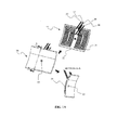
- FIGs. 1 and 2-4 show an embodiment of an electromagnetic oil tank heating unit 100 according to the principle of the present invention.
- the electromagnetic oil tank heating unit 100 is intended to be mobile and comprising a generator 20 capable of generating high frequency electrical current connected to a transformer 25 and a cooling unit 40 or 40", an induction plate 30, with induction coil 35 embedded therein, connected to the transformer 25 and at least one cooling unit 40, 40" providing cooling liquid to the transformer 25 and the induction plate 30.
- the generator 20, the transformer 25, the induction plate 30, the cooling unit 40, 40" are arranged on a frame 45 equipped with wheels 50 to permit mobility of the unit so as to allow moving the heating to a specific location along the length of an oil tank 55.
- the frame 45 is configured to include mechanical means allowing the frame and thus the induction plate 30 supported thereon to move up and down, and forward and backward relative to the oil tank 55.
- the generator 20 is capable of generating high voltage with high frequency to the transformer25.
- the capacity of the generator 20 determines the level of frequency and the amount of output voltage which correlate to the ability to generate heat at the induction plate 30 and hence affect the time frame by which required to heat the oil tank 55. Therefore, it is desirable to be able to control the level of output voltage in order to attain an optimum time frame for heating while minimizing power consumption of the generator 20. Therefore, according to the principle of the present invention, the generator 20 is connected by a high voltage cable 23 to the transformer 25 of which supplies the current to the induction coil 35 and regulates impedance of the induction coil 35 within the induction plate 30 to correspond with the output voltage generated by the generator 20.
- the output voltage can be adjusted by way of a temperature control unit21 in the generator 20.
- the heating temperature is regulated by way of a temperature sensor 22disposed on the induction pate 30.
- the temperature sensor 22 at the induction plate 30 detects the temperature at the time of heating and sends the read temperature to the temperature control unit 21 of generator 20 and thus the output voltage is adjusted.
- the transformer 25 transforms the high voltage generated by the generator 20 into high current output in order to supply the induction coil 35 within the induction plate 30.
- the cooling unit 40, 40" supplies cooling fluid, for example, water, to the generator 20 via flexible water tube 41,41", the transformer 25 and subsequently to the induction coil 35.
- the cooling unit is a closed unit wherein cooling fluid, i.e. water is added into the unit and circulates within the unit and the circulation and the pressure of the cooling fluid is regulated with assistance of a water pump (not shown) disposed within the unit to regulate water pressure.
- the cooling fluid exits the cooling unit and continuously and simultaneously enters the transformer 25 and the induction coil 35 to provide cooling to the transformer 25 and the induction coil 35.
- the returning cooling fluid is cooled down again with coolant or any other known means, at the cooling unit 40, 40" and re-enters the system. It is worthwhile to note that the cooling fluid enters and cools the transformer 25 while the cooling fluid does not come into direct contact with the electrical current or parts of the transformer 25.
- the electromagnetic oil tank heating unit100 comprises two separate cooling units 40 and 40" wherein the cooling unit 40 supplies cooling fluid to the transformer 25 and subsequently to the induction coil 35; and wherein the cooling unit 40" supplies cooling fluid to the generator 20.
- the cooling unit 40 supplies cooling fluid to the generator 20.
- a person skilled in the art would appreciate that a single cooling unit capable of supplying cooling fluid to all of the generator 20, transformer 25 and the induction coil 35 is also possible.
- the induction plate 30 having induction coil 35 embedded therein receives current from the transformer 25 via connecting member 26 which connects the induction coil 35 with the transformer 25.
- the induction coil 35 emits high concentration eddy currents which heats the wall of the oil tank 55 where such heat is subsequently transferred to the oil contained inside the oil tank 55 reducing viscosity of the oil.
- the induction plate 30, and thus the induction coil 35 is configured to possess a shape corresponding to the shape of the surface of the oil tank 55 or a portion thereof of which heating is required.
- the induction plate 30 is configured to have an arch-rectangular shape to correspond to the arch of the wall of a rail oil tanker 55 so as to allow good contact between the induction plate 30 and the oil tank 55.
- the external shell 31 of the induction plate 30 is preferably made of epoxy resin composite which is molded over the induction coil 35 to avoid electrical contact between the induction coil 35 and the wall of the oil tank 55 to avoid unwanted ignition or spark, as well as reducing possible leakage of cooling fluid.
- FIG. 1A shows an exemplary example of the induction coil 35 embedded inside the induction plate 30.
- the induction coil 35 is preferably made of a hollow tube of high electrical conducting metals such as copper.
- the induction coil 35 is wounded in a flat rectangular shape to correspond to the shape of the induction plate 30.
- the size of the coil of the induction coil 35 may be adjusted to suit the size of the area of which heating is desired. Another pattern of arrangement of the induction coil 35 is also possible. It is possible to arrange more than one set of induction coil 35 within the induction plate 30.
- the hollow induction coil 35 is provided with a cooling fluid inlet 36 and a cooling fluid outlet 37.
- the cooling fluid inlet 36 and connected to and receives, via fluid inlet 36, cooling fluid from the cooling unit 40 so as to cool the induction coil 35.
- the cooling fluid exits the induction plate 30 via fluid outlet 37 and returns to the cooling unit 40, 40" to be cooled down once again and re-enter the induction plate 30 as a loop.
- the generator 20, the transformer 25, the induction plate 30, the cooling unit 40, 40" are arranged on the frame 45.
- the said frame 45 comprising a base frame 46 of which substantially rectangular shape, square shape is also possible, and an operably movable (up-down) inner frame 47 with foldable frame 48 assembled thereon.
- the generator 20 and the cooling unit 40, 40" are secured to designated locations on the base frame 46 away from the moving zone of the inner frame 47.
- the transformer 25 and the induction plate 30 connected to the said transformer 25 are supported on support frame 60 of which engage to a pair opposing support railing frame 65 each of which supported on the said operably movable inner frame 47 ( FIG. 1 ).
- the movable inner frame 47 is configured to move up or down so as to adjust the height of the induction plate 30 relative to the height of the area on the wall of the oil tank 55 where heating is desired.
- the ability to move up and down of the inner frame 47 may be by way of known mechanical means such as extendable-collapsible (foldable) frames 48 or hydraulics49 so as to compress or extend the height of the induction plate 35 as illustrated in FIGs 2 and 3 , respectively.
- the induction plate 30 and the transformer 25 while supported on the inner frame 47 is mounted on the support frame 60 made of non-conductive materials slidably mounted on a pair of railing frame 65 so as to allow the induction plate 30 while connected to the transformer 25 to move forward and backward in order to project the induction plate 30 closer to or away from the oil tank 55 as shown in FIGs. 3 and 4 .
- a pair of support rod 72 is connected to the support plate 30 on one end and while another end is supported to an induction plate supporter 71 which supports the weight of the induction plate 30.
- the induction plate 30 may be actuated to move forward or backward by way of manual operation (i.e. hand pulling or pushing), or other suitable electrical control means.
- An adjustable guide rod 70 is provided on and connected to the railing frame 65.
- the adjustable guide rod 70 is configured to fine adjust the angle of the induction plate 30 relative to the oil tank 55 in order to project the induction plate 30 at a specific posture relative to the oil tank 55.
- the adjustable guide rod 70 may be pushed downward (thereby elevating the railing frame 65 which the induction plate 30 is supported) to cause the induction plate (the front end, while at an extended posture as in FIG. 1 or 4 ) to tilt downward projecting the induction plate 30 closer to the lower section of the oil tank 55.
- the frame 45 more specifically, the base frame 47, as previously mentioned is equipped with wheels 50 to allow mobility of the electromagnetic oil tank heating unit 100 to a desired location.
- the electromagnetic oil tank heating unit 100 is equipped with wheel brakes (not shown) to ensure stability of the unit once it reaches the desired location and while the unit is in operation.
- the frame 45, more specifically, the base frame 47 further comprises foldable footing 75, preferably at around each corner of the base frame 47so as to secure the heating unit 100 to the ground while the heating unit 100is in operation.
- the invention discloses a stationary electromagnetic oil tank heating system configured to heat heavy oil contained inside an oil tank in one time.
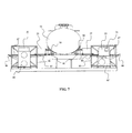
- FIGs 5-7 show an embodiment of an electromagnetic oil tank heating system 200 according to the principle of the present invention.
- the electromagnetic oil tank heating system 200 comprises multiple electromagnetic oil tank heating units 100 each of which very much possesses the features and characteristics as described in the earlier described embodiment of the first aspect of the invention.
- the invention discloses electromagnetic oil tank heating unit 100 each of which is intended to be a stationary type rather than a mobile type. Therefore, in this embodiment, the electromagnetic oil tank heating unit 100 is comprising a stationary frame 85 and without wheels and without footing.
- the generator 20, the transformer 25, the cooling unit 40, 40" and the induction plate 30 are assembled on to the said frame 85 as in the previously described embodiment.
- FIG 5 shows an exemplary arrangement of the electromagnetic oil tank heating system 200 comprising a plurality of electromagnetic oil tank heating units 100 of which without wheels and without footing fastened or secured to the ground. Each unit is arranged side by side to the next and subsequent units along the length, and on each side of the oil tank 55.
- the induction plate 30 of each of the electromagnetic oil tank heating unit 100 is maneuvered forward to project the induction plate to the wall of the oil tank 55 so as to heat the wall of the oil tank 55 as shown FIGs. 6-7 .
- the transformer 25 and the induction plate 30 connected to the transformer 25 are supported on a pair of spaced-apart railing 87 prepared on the frame 45.
- the railing 87 having a support 90 and a support 91 disposed thereon to provide support to the induction plate 30, the transformer 25.
- the transformer 25 is equipped with wheels 86 and configured to be movable along the railing 87.
- the wheels 86 are disposed to the front and to the rear (relative forward and backward moving direction of the transformer 25 and the induction plate 30) of the transformer 25.
- the wheels 86 move along a corresponding groove or channel (not shown) prepared on each of the railing 87.
- the groove or the channel restrict the wheels 86 to move in straight line only and hence avoid derail of the movingtransformer 25 and the induction plate 30.
- the oil tank heating unit 100 is prepared with a different configuration of handle.
- the handle is realized as an adjustable handle 88 which serves the same function as with the adjustable guide rod 70 of the earlier described embodiment, see FIG. 1 . That is, the handle 88 serves to fine adjust the transformer 25 and the induction plate 30 to project at the required angle relative to the oil tank 55.
- This embodiment and its arrangement as described is particularly useful for drive-through stationary heating of the oil tank 55 wherein the oil tank to be heated is driven(while on an oil tanker) into a position and driven away once the heating is completed.
- the same principle may also be utilized for rail tanker wherein multiple units of the electromagnetic oil tank heating unit 100 are lined along the tanker platform and once the rail tanker is moved into position, the induction plate 30 is moved forward to heat the lower portion of the oil tank 55 and is retracted backward once the heating is completed to enable the rail tanker to move and drive the oil tank 55 away from the station.
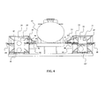
- FIGs. 8-10 show another embodiment of the electromagnetic oil tank heating system 200 according to the principle of the present invention.
- This embodiment is also intended to be a stationary system in which the system comprises a plurality of oil tank heating units 100 arranged side by side subsequent to the next unit along the length of the oil tank 55 on a pair of opposing, paralleled station rails 110.
- the cooling unit 40, 40" and the generator 20 are not mounted onto a frame 112 equipped with wheels 111 so as to move the unit along the rail 110.
- the cooling unit 40, 40" are supported on a cooling unit support frame 115 and the generator 20 are arranged on a generator 20 support frame 114 at a central location away from the frame 45 on which the transformer 25 and the induction plate 30 are supported.
- the transformer 25 and the induction plate 30 communicate with the cooling unit 40, 40 and generator 20 via cables, preferably underground (not shown).
- the cooling unit support frame 115 and the generator support frame 114 are not essential elements. Other forms and means to store and support both the cooling unit and the generator are possible.
- the electromagnetic oil tank heating system 200 comprises multiple units of electromagnetic oil tank heating units 100 of which arranged in a stationary type arrangement.
- each of the electromagnetic oil tank heating units 100 still comprises the main features and characteristics of generator 20, the transformer 25, the induction plate 30, the induction coil 35 and the cooling unit as described in earlier embodiments.
- this embodiment is characterized from the previous embodiments in that only the transformer 25 and the induction plate 30 are supported on the frame 45.
- the transformer 25 and the induction plate 30 are correspondingly connected to the respective generator 20 and the respective cooling unit 40, 40" via cables and tubes (not shown) at a central station away from the frame 45 on which the transformer 25 and the induction plate 30 are supported. Similar to the second embodiment as previously described in relation to FIGs.
- the induction plate 30 of each of the electromagnetic oil tank heating units 100 is maneuvered forward or backward to project the induction plate 30 toward or away from the wall of the oil tank 55 so as to heat the wall of the oil tank 55 as shown FIGs. 9-10 .
- the frame 45 is prepared as a rigid frame and is not intended to collapse and extend in order to move the induction plate 30 up or down. In this embodiment, the frame 45 is more like a table of which the transformer is supported thereon.
- the transformer 25 is communicating with the induction plate 30, and a support member120 which, engaged to the transformer 25, is provided to support the induction plate 30.
- the bottom of the transformer 25 is equipped with wheels disposed to the front and to the rear of the transformer 25 (relative forward and backward moving direction of the transformer 25 and the induction plate 30) which move along a pair of spaced-apart paralleled grooves or channels 113 prepared on the surface of the top of the frame 45.
- the transformer 25 is prepared with a hand rail116 for maneuvering the transformer 25 and the induction plate 30 forward or backward along the said groove or channels 113.
- this embodiment and its arrangement as described is particularly useful for drive-through stationary heating of the oil tank 55 wherein the oil tank to be heated is driven(while on an oil tanker) into a position and driven away once the heating is completed.
- the same principle may also be utilized for rail tanker wherein multiple units of the electromagnetic oil tank heating unit 100 are lined along the train platform and once the rail tanker is moved into position, the induction plate 30 is moved forward to heat the lower portion of the oil tank 55 and is retracted backward once the heating is completed to enable the rail tanker to move and drive the oil tanker 55 away from the station.
- the frame 45 may be prepared without the extendable and collapsible inner frame 47 and foldable frame 48.
- the electromagnetic oil tank heating unit 100 without the ability to adjust the height of the induction plate 30 is possible where the oil tanks 55 to be heated are of uniformity height.
- the oil tank for rail oil tanker in most instances is positioned onto the rail oil tanker at a specific predetermined height.
- the induction plate 30 may be supported on the frame 45 at fixed height such that the induction plate 30 can be projected at specific portion of the oil tank 55, a lower portion of the oil tank 55 for example. Therefore, in such case adjusting the height of the induction plate 30 by height adjusting means is not a necessary feature.
- the frame may be prepared without the inner frame 47.
- cooling unit with higher capacity such that a single unit of the cooling unit 40 is able to supply cooling fluid to multiple units of transformer and/or generators.
- the generator with higher capacity may also be connected to multiple units of transformer.
- the principle of electromagnetic oil tank heating according to the principle of the present invention may not necessarily be limited to heating oil tank only, but may be also be applied for heating other oil containing, oil carrying, oil transporting vessels.
- the heating unit, especially, the induction plate may be prepared to heat different kinds of vessels, such as above ground oil pipeline, wherein the induction plate may be prepared as a clamp of which configured to clamp onto the pipeline and heat the pipeline.
Landscapes
- Engineering & Computer Science (AREA)
- Mechanical Engineering (AREA)
- Physics & Mathematics (AREA)
- Electromagnetism (AREA)
- Transportation (AREA)
- Thermal Sciences (AREA)
- Chemical & Material Sciences (AREA)
- Combustion & Propulsion (AREA)
- General Engineering & Computer Science (AREA)
- General Induction Heating (AREA)
Applications Claiming Priority (1)
| Application Number | Priority Date | Filing Date | Title |
|---|---|---|---|
| US13/859,288 US9521707B2 (en) | 2013-04-09 | 2013-04-09 | Electromagnetic oil tank heating unit |
Publications (2)
| Publication Number | Publication Date |
|---|---|
| EP2790465A1 true EP2790465A1 (fr) | 2014-10-15 |
| EP2790465B1 EP2790465B1 (fr) | 2016-09-14 |
Family
ID=48625748
Family Applications (1)
| Application Number | Title | Priority Date | Filing Date |
|---|---|---|---|
| EP13170032.0A Not-in-force EP2790465B1 (fr) | 2013-04-09 | 2013-05-31 | Unité de chauffage électromagnétique de réservoir d'huile |
Country Status (3)
| Country | Link |
|---|---|
| US (1) | US9521707B2 (fr) |
| EP (1) | EP2790465B1 (fr) |
| KR (1) | KR20140122160A (fr) |
Cited By (1)
| Publication number | Priority date | Publication date | Assignee | Title |
|---|---|---|---|---|
| EP3420263A4 (fr) * | 2016-02-24 | 2019-10-30 | IcpTech Pty Ltd | Appareil et procédé pour chauffer une canalisation sous-marine |
Families Citing this family (3)
| Publication number | Priority date | Publication date | Assignee | Title |
|---|---|---|---|---|
| CN107128607A (zh) * | 2016-02-26 | 2017-09-05 | 扬州市鑫源电气有限公司 | 一种新型特高压试验变压器沉筒运输结构 |
| GB2557667A (en) * | 2016-12-15 | 2018-06-27 | Ab Skf Publ | Induction heating device |
| US11690144B2 (en) | 2019-03-11 | 2023-06-27 | Accelware Ltd. | Apparatus and methods for transporting solid and semi-solid substances |
Citations (6)
| Publication number | Priority date | Publication date | Assignee | Title |
|---|---|---|---|---|
| JP2004099148A (ja) * | 2002-09-12 | 2004-04-02 | Nisshin Flour Milling Inc | 粉体の投入時における結露防止方法 |
| CN201056397Y (zh) * | 2007-06-06 | 2008-05-07 | 中国石油天然气股份有限公司 | 储罐电磁加温装置 |
| CN201657384U (zh) | 2010-04-13 | 2010-11-24 | 东莞市粤塑建材有限公司 | 一种新型电磁感应线盘 |
| CN201753171U (zh) | 2010-07-30 | 2011-03-02 | 魏燕 | 整体感应加热式储油罐系统 |
| CN201842413U (zh) | 2010-10-08 | 2011-05-25 | 陈忠 | 储油罐电磁加热装置 |
| CN202328726U (zh) | 2011-11-29 | 2012-07-11 | 西安动化实业有限公司 | 一种感应式流体加热炉 |
Family Cites Families (22)
| Publication number | Priority date | Publication date | Assignee | Title |
|---|---|---|---|---|
| US1914585A (en) * | 1931-05-20 | 1933-06-20 | Union Tank Car Co | Tank heating device |
| US2886690A (en) * | 1955-02-28 | 1959-05-12 | Thomas J Crawford | Method and apparatus for induction brazing of metal tubing |
| US3176764A (en) * | 1961-01-26 | 1965-04-06 | J B Beaird Company Inc | Integral tank shell heat-exchange coils |
| US3228466A (en) * | 1964-04-24 | 1966-01-11 | Union Tank Car Co | External heating arrangement for a storage tank |
| US3596036A (en) * | 1970-03-16 | 1971-07-27 | Ajax Magnethermic Corp | Induction heater |
| US3705285A (en) * | 1971-11-05 | 1972-12-05 | Growth Intern Inc | Mobile apparatus for the induction heating of metal ingots |
| FR2399299A1 (fr) * | 1977-08-05 | 1979-03-02 | Tocco Stel | Procede et dispositif de soudage bout a bout par induction de pieces metalliques, notamment de section irreguliere |
| US4414462A (en) * | 1981-07-17 | 1983-11-08 | General American Transportation Corporation | Tank car heating system |
| US5186755A (en) * | 1990-05-29 | 1993-02-16 | Commercial Resins Company | Girth weld heating and coating system |
| US5122363A (en) * | 1990-12-07 | 1992-06-16 | Board Of Regents, The University Of Texas System | Zeolite-enclosed transistion and rare earth metal ions as contrast agents for the gastrointestinal tract |
| US5337858A (en) * | 1993-01-19 | 1994-08-16 | Genie Industries | Safety system for multi-stage lifts |
| US5468117A (en) * | 1994-09-08 | 1995-11-21 | Lobko; Mikhail A. | Heating of tank car walls for ejecting frozen or congealed cargo |
| US5872352A (en) * | 1995-03-22 | 1999-02-16 | Honda Ginken Kogyo Kabushiki Kaisha | Swingable induction heating chamber for melting ingot for metal casting |
| US6302961B1 (en) * | 1999-07-12 | 2001-10-16 | Ennis Automotive, Inc. | Apparatus for applying a liquid coating to electrical components |
| US6956189B1 (en) * | 2001-11-26 | 2005-10-18 | Illinois Tool Works Inc. | Alarm and indication system for an on-site induction heating system |
| US8038931B1 (en) * | 2001-11-26 | 2011-10-18 | Illinois Tool Works Inc. | On-site induction heating apparatus |
| US6911089B2 (en) * | 2002-11-01 | 2005-06-28 | Illinois Tool Works Inc. | System and method for coating a work piece |
| JP2005019374A (ja) * | 2003-05-30 | 2005-01-20 | Tokyo Denki Univ | 携帯用電磁誘導加熱装置 |
| US6875966B1 (en) * | 2004-03-15 | 2005-04-05 | Nexicor Llc | Portable induction heating tool for soldering pipes |
| US7963230B2 (en) * | 2006-08-11 | 2011-06-21 | R.J. Corman Derailment Services, Llc | Shield assembly for railroad tank car |
| US7781708B2 (en) * | 2008-05-23 | 2010-08-24 | Team Industrial Services, Inc. | System for inductive heating of workpiece using coiled assemblies |
| US8716636B2 (en) * | 2009-10-02 | 2014-05-06 | John C. Bollman | Arrangement and method for powering inductors for induction hardening |
-
2013
- 2013-04-09 US US13/859,288 patent/US9521707B2/en not_active Expired - Fee Related
- 2013-05-31 EP EP13170032.0A patent/EP2790465B1/fr not_active Not-in-force
- 2013-09-05 KR KR20130106754A patent/KR20140122160A/ko not_active Abandoned
Patent Citations (6)
| Publication number | Priority date | Publication date | Assignee | Title |
|---|---|---|---|---|
| JP2004099148A (ja) * | 2002-09-12 | 2004-04-02 | Nisshin Flour Milling Inc | 粉体の投入時における結露防止方法 |
| CN201056397Y (zh) * | 2007-06-06 | 2008-05-07 | 中国石油天然气股份有限公司 | 储罐电磁加温装置 |
| CN201657384U (zh) | 2010-04-13 | 2010-11-24 | 东莞市粤塑建材有限公司 | 一种新型电磁感应线盘 |
| CN201753171U (zh) | 2010-07-30 | 2011-03-02 | 魏燕 | 整体感应加热式储油罐系统 |
| CN201842413U (zh) | 2010-10-08 | 2011-05-25 | 陈忠 | 储油罐电磁加热装置 |
| CN202328726U (zh) | 2011-11-29 | 2012-07-11 | 西安动化实业有限公司 | 一种感应式流体加热炉 |
Cited By (1)
| Publication number | Priority date | Publication date | Assignee | Title |
|---|---|---|---|---|
| EP3420263A4 (fr) * | 2016-02-24 | 2019-10-30 | IcpTech Pty Ltd | Appareil et procédé pour chauffer une canalisation sous-marine |
Also Published As
| Publication number | Publication date |
|---|---|
| KR20140122160A (ko) | 2014-10-17 |
| US20140299594A1 (en) | 2014-10-09 |
| EP2790465B1 (fr) | 2016-09-14 |
| US9521707B2 (en) | 2016-12-13 |
Similar Documents
| Publication | Publication Date | Title |
|---|---|---|
| EP2790465B1 (fr) | Unité de chauffage électromagnétique de réservoir d'huile | |
| US10668829B2 (en) | Passive flux bridge for charging electric vehicles | |
| KR101727785B1 (ko) | 유도에너지전달장치 | |
| KR101704934B1 (ko) | 최대수신전력 자동 위치정렬을 이용한 무선충전패드 및 이를 이용한 무선충전방법 | |
| JP2015015891A (ja) | 非接触電力供給装置 | |
| CN106165249B (zh) | 非接触供电系统和车辆供电装置 | |
| WO2022247546A1 (fr) | Machine de mise à niveau intelligente à haute fréquence intégrée et son procédé de fonctionnement | |
| CN104575956B (zh) | 一种能够装入不同高度箱体的变压器 | |
| KR20170038903A (ko) | 놀이기구 차량의 제동 또는 시동을 위한 시스템 및 방법 | |
| CN205973229U (zh) | 一种电力电缆搬运移动放线装置 | |
| JP2005289101A (ja) | 非接触給電システム | |
| JP6067597B2 (ja) | 磁気浮上式搬送装置 | |
| JP6567046B2 (ja) | 誘導電力伝送システムを動作させる方法及び誘導電力伝送システム | |
| US20170012459A1 (en) | Wireless power transfer system and object power supply device | |
| WO2010116566A1 (fr) | Appareil d'alimentation par induction | |
| CN101614313B (zh) | 用于高强度连续复合管的外保温层包覆设备 | |
| CN205577555U (zh) | 立体车库 | |
| CN206977736U (zh) | 一种高频感应加热一体机 | |
| US11839009B2 (en) | Portable induction heating device for coating removal | |
| RU78554U1 (ru) | Устройство для нагрева наружной поверхности трубопровода | |
| KR200489677Y1 (ko) | 고주파 트랙케이블을 이용한 무선 전원공급 기반의 대차 이송 시스템 | |
| CN103137110B (zh) | 一种吉他支架 | |
| CN207397863U (zh) | 干式变压器 | |
| CN107774487A (zh) | 一种电热管喷涂装置 | |
| CN215362924U (zh) | 一种晶闸管对接保护支架 |
Legal Events
| Date | Code | Title | Description |
|---|---|---|---|
| PUAI | Public reference made under article 153(3) epc to a published international application that has entered the european phase |
Free format text: ORIGINAL CODE: 0009012 |
|
| 17P | Request for examination filed |
Effective date: 20130531 |
|
| AK | Designated contracting states |
Kind code of ref document: A1 Designated state(s): AL AT BE BG CH CY CZ DE DK EE ES FI FR GB GR HR HU IE IS IT LI LT LU LV MC MK MT NL NO PL PT RO RS SE SI SK SM TR |
|
| AX | Request for extension of the european patent |
Extension state: BA ME |
|
| R17P | Request for examination filed (corrected) |
Effective date: 20150415 |
|
| RBV | Designated contracting states (corrected) |
Designated state(s): AL AT BE BG CH CY CZ DE DK EE ES FI FR GB GR HR HU IE IS IT LI LT LU LV MC MK MT NL NO PL PT RO RS SE SI SK SM TR |
|
| REG | Reference to a national code |
Ref country code: DE Ref legal event code: R079 Ref document number: 602013011356 Country of ref document: DE Free format text: PREVIOUS MAIN CLASS: H05B0006100000 Ipc: B67D0007820000 |
|
| GRAP | Despatch of communication of intention to grant a patent |
Free format text: ORIGINAL CODE: EPIDOSNIGR1 |
|
| RIC1 | Information provided on ipc code assigned before grant |
Ipc: B67D 7/82 20100101AFI20160317BHEP Ipc: H05B 6/10 20060101ALI20160317BHEP |
|
| INTG | Intention to grant announced |
Effective date: 20160415 |
|
| GRAS | Grant fee paid |
Free format text: ORIGINAL CODE: EPIDOSNIGR3 |
|
| GRAA | (expected) grant |
Free format text: ORIGINAL CODE: 0009210 |
|
| AK | Designated contracting states |
Kind code of ref document: B1 Designated state(s): AL AT BE BG CH CY CZ DE DK EE ES FI FR GB GR HR HU IE IS IT LI LT LU LV MC MK MT NL NO PL PT RO RS SE SI SK SM TR |
|
| REG | Reference to a national code |
Ref country code: GB Ref legal event code: FG4D |
|
| REG | Reference to a national code |
Ref country code: CH Ref legal event code: EP |
|
| REG | Reference to a national code |
Ref country code: IE Ref legal event code: FG4D |
|
| REG | Reference to a national code |
Ref country code: AT Ref legal event code: REF Ref document number: 828748 Country of ref document: AT Kind code of ref document: T Effective date: 20161015 |
|
| REG | Reference to a national code |
Ref country code: DE Ref legal event code: R096 Ref document number: 602013011356 Country of ref document: DE |
|
| REG | Reference to a national code |
Ref country code: LT Ref legal event code: MG4D |
|
| REG | Reference to a national code |
Ref country code: NL Ref legal event code: MP Effective date: 20160914 |
|
| PG25 | Lapsed in a contracting state [announced via postgrant information from national office to epo] |
Ref country code: FI Free format text: LAPSE BECAUSE OF FAILURE TO SUBMIT A TRANSLATION OF THE DESCRIPTION OR TO PAY THE FEE WITHIN THE PRESCRIBED TIME-LIMIT Effective date: 20160914 Ref country code: RS Free format text: LAPSE BECAUSE OF FAILURE TO SUBMIT A TRANSLATION OF THE DESCRIPTION OR TO PAY THE FEE WITHIN THE PRESCRIBED TIME-LIMIT Effective date: 20160914 Ref country code: LT Free format text: LAPSE BECAUSE OF FAILURE TO SUBMIT A TRANSLATION OF THE DESCRIPTION OR TO PAY THE FEE WITHIN THE PRESCRIBED TIME-LIMIT Effective date: 20160914 Ref country code: NO Free format text: LAPSE BECAUSE OF FAILURE TO SUBMIT A TRANSLATION OF THE DESCRIPTION OR TO PAY THE FEE WITHIN THE PRESCRIBED TIME-LIMIT Effective date: 20161214 Ref country code: HR Free format text: LAPSE BECAUSE OF FAILURE TO SUBMIT A TRANSLATION OF THE DESCRIPTION OR TO PAY THE FEE WITHIN THE PRESCRIBED TIME-LIMIT Effective date: 20160914 |
|
| REG | Reference to a national code |
Ref country code: AT Ref legal event code: MK05 Ref document number: 828748 Country of ref document: AT Kind code of ref document: T Effective date: 20160914 |
|
| PG25 | Lapsed in a contracting state [announced via postgrant information from national office to epo] |
Ref country code: GR Free format text: LAPSE BECAUSE OF FAILURE TO SUBMIT A TRANSLATION OF THE DESCRIPTION OR TO PAY THE FEE WITHIN THE PRESCRIBED TIME-LIMIT Effective date: 20161215 Ref country code: LV Free format text: LAPSE BECAUSE OF FAILURE TO SUBMIT A TRANSLATION OF THE DESCRIPTION OR TO PAY THE FEE WITHIN THE PRESCRIBED TIME-LIMIT Effective date: 20160914 Ref country code: NL Free format text: LAPSE BECAUSE OF FAILURE TO SUBMIT A TRANSLATION OF THE DESCRIPTION OR TO PAY THE FEE WITHIN THE PRESCRIBED TIME-LIMIT Effective date: 20160914 Ref country code: SE Free format text: LAPSE BECAUSE OF FAILURE TO SUBMIT A TRANSLATION OF THE DESCRIPTION OR TO PAY THE FEE WITHIN THE PRESCRIBED TIME-LIMIT Effective date: 20160914 |
|
| PG25 | Lapsed in a contracting state [announced via postgrant information from national office to epo] |
Ref country code: EE Free format text: LAPSE BECAUSE OF FAILURE TO SUBMIT A TRANSLATION OF THE DESCRIPTION OR TO PAY THE FEE WITHIN THE PRESCRIBED TIME-LIMIT Effective date: 20160914 Ref country code: RO Free format text: LAPSE BECAUSE OF FAILURE TO SUBMIT A TRANSLATION OF THE DESCRIPTION OR TO PAY THE FEE WITHIN THE PRESCRIBED TIME-LIMIT Effective date: 20160914 |
|
| PG25 | Lapsed in a contracting state [announced via postgrant information from national office to epo] |
Ref country code: SK Free format text: LAPSE BECAUSE OF FAILURE TO SUBMIT A TRANSLATION OF THE DESCRIPTION OR TO PAY THE FEE WITHIN THE PRESCRIBED TIME-LIMIT Effective date: 20160914 Ref country code: BG Free format text: LAPSE BECAUSE OF FAILURE TO SUBMIT A TRANSLATION OF THE DESCRIPTION OR TO PAY THE FEE WITHIN THE PRESCRIBED TIME-LIMIT Effective date: 20161214 Ref country code: CZ Free format text: LAPSE BECAUSE OF FAILURE TO SUBMIT A TRANSLATION OF THE DESCRIPTION OR TO PAY THE FEE WITHIN THE PRESCRIBED TIME-LIMIT Effective date: 20160914 Ref country code: AT Free format text: LAPSE BECAUSE OF FAILURE TO SUBMIT A TRANSLATION OF THE DESCRIPTION OR TO PAY THE FEE WITHIN THE PRESCRIBED TIME-LIMIT Effective date: 20160914 Ref country code: SM Free format text: LAPSE BECAUSE OF FAILURE TO SUBMIT A TRANSLATION OF THE DESCRIPTION OR TO PAY THE FEE WITHIN THE PRESCRIBED TIME-LIMIT Effective date: 20160914 Ref country code: BE Free format text: LAPSE BECAUSE OF FAILURE TO SUBMIT A TRANSLATION OF THE DESCRIPTION OR TO PAY THE FEE WITHIN THE PRESCRIBED TIME-LIMIT Effective date: 20160914 Ref country code: PT Free format text: LAPSE BECAUSE OF FAILURE TO SUBMIT A TRANSLATION OF THE DESCRIPTION OR TO PAY THE FEE WITHIN THE PRESCRIBED TIME-LIMIT Effective date: 20170116 Ref country code: IS Free format text: LAPSE BECAUSE OF FAILURE TO SUBMIT A TRANSLATION OF THE DESCRIPTION OR TO PAY THE FEE WITHIN THE PRESCRIBED TIME-LIMIT Effective date: 20170114 Ref country code: PL Free format text: LAPSE BECAUSE OF FAILURE TO SUBMIT A TRANSLATION OF THE DESCRIPTION OR TO PAY THE FEE WITHIN THE PRESCRIBED TIME-LIMIT Effective date: 20160914 Ref country code: ES Free format text: LAPSE BECAUSE OF FAILURE TO SUBMIT A TRANSLATION OF THE DESCRIPTION OR TO PAY THE FEE WITHIN THE PRESCRIBED TIME-LIMIT Effective date: 20160914 |
|
| REG | Reference to a national code |
Ref country code: DE Ref legal event code: R097 Ref document number: 602013011356 Country of ref document: DE |
|
| PG25 | Lapsed in a contracting state [announced via postgrant information from national office to epo] |
Ref country code: IT Free format text: LAPSE BECAUSE OF FAILURE TO SUBMIT A TRANSLATION OF THE DESCRIPTION OR TO PAY THE FEE WITHIN THE PRESCRIBED TIME-LIMIT Effective date: 20160914 |
|
| PLBE | No opposition filed within time limit |
Free format text: ORIGINAL CODE: 0009261 |
|
| STAA | Information on the status of an ep patent application or granted ep patent |
Free format text: STATUS: NO OPPOSITION FILED WITHIN TIME LIMIT |
|
| PG25 | Lapsed in a contracting state [announced via postgrant information from national office to epo] |
Ref country code: DK Free format text: LAPSE BECAUSE OF FAILURE TO SUBMIT A TRANSLATION OF THE DESCRIPTION OR TO PAY THE FEE WITHIN THE PRESCRIBED TIME-LIMIT Effective date: 20160914 |
|
| 26N | No opposition filed |
Effective date: 20170615 |
|
| PG25 | Lapsed in a contracting state [announced via postgrant information from national office to epo] |
Ref country code: LU Free format text: LAPSE BECAUSE OF NON-PAYMENT OF DUE FEES Effective date: 20170531 |
|
| PG25 | Lapsed in a contracting state [announced via postgrant information from national office to epo] |
Ref country code: SI Free format text: LAPSE BECAUSE OF FAILURE TO SUBMIT A TRANSLATION OF THE DESCRIPTION OR TO PAY THE FEE WITHIN THE PRESCRIBED TIME-LIMIT Effective date: 20160914 |
|
| REG | Reference to a national code |
Ref country code: CH Ref legal event code: PL |
|
| GBPC | Gb: european patent ceased through non-payment of renewal fee |
Effective date: 20170531 |
|
| PG25 | Lapsed in a contracting state [announced via postgrant information from national office to epo] |
Ref country code: MC Free format text: LAPSE BECAUSE OF FAILURE TO SUBMIT A TRANSLATION OF THE DESCRIPTION OR TO PAY THE FEE WITHIN THE PRESCRIBED TIME-LIMIT Effective date: 20160914 |
|
| REG | Reference to a national code |
Ref country code: IE Ref legal event code: MM4A |
|
| PG25 | Lapsed in a contracting state [announced via postgrant information from national office to epo] |
Ref country code: LI Free format text: LAPSE BECAUSE OF NON-PAYMENT OF DUE FEES Effective date: 20170531 Ref country code: CH Free format text: LAPSE BECAUSE OF NON-PAYMENT OF DUE FEES Effective date: 20170531 |
|
| REG | Reference to a national code |
Ref country code: FR Ref legal event code: ST Effective date: 20180131 |
|
| PG25 | Lapsed in a contracting state [announced via postgrant information from national office to epo] |
Ref country code: GB Free format text: LAPSE BECAUSE OF NON-PAYMENT OF DUE FEES Effective date: 20170531 Ref country code: IE Free format text: LAPSE BECAUSE OF NON-PAYMENT OF DUE FEES Effective date: 20170531 |
|
| PG25 | Lapsed in a contracting state [announced via postgrant information from national office to epo] |
Ref country code: FR Free format text: LAPSE BECAUSE OF NON-PAYMENT OF DUE FEES Effective date: 20170531 |
|
| PG25 | Lapsed in a contracting state [announced via postgrant information from national office to epo] |
Ref country code: MT Free format text: LAPSE BECAUSE OF NON-PAYMENT OF DUE FEES Effective date: 20170531 |
|
| PG25 | Lapsed in a contracting state [announced via postgrant information from national office to epo] |
Ref country code: AL Free format text: LAPSE BECAUSE OF FAILURE TO SUBMIT A TRANSLATION OF THE DESCRIPTION OR TO PAY THE FEE WITHIN THE PRESCRIBED TIME-LIMIT Effective date: 20160914 |
|
| PG25 | Lapsed in a contracting state [announced via postgrant information from national office to epo] |
Ref country code: HU Free format text: LAPSE BECAUSE OF FAILURE TO SUBMIT A TRANSLATION OF THE DESCRIPTION OR TO PAY THE FEE WITHIN THE PRESCRIBED TIME-LIMIT; INVALID AB INITIO Effective date: 20130531 |
|
| PGFP | Annual fee paid to national office [announced via postgrant information from national office to epo] |
Ref country code: DE Payment date: 20190521 Year of fee payment: 7 |
|
| PG25 | Lapsed in a contracting state [announced via postgrant information from national office to epo] |
Ref country code: CY Free format text: LAPSE BECAUSE OF FAILURE TO SUBMIT A TRANSLATION OF THE DESCRIPTION OR TO PAY THE FEE WITHIN THE PRESCRIBED TIME-LIMIT Effective date: 20160914 |
|
| PG25 | Lapsed in a contracting state [announced via postgrant information from national office to epo] |
Ref country code: MK Free format text: LAPSE BECAUSE OF FAILURE TO SUBMIT A TRANSLATION OF THE DESCRIPTION OR TO PAY THE FEE WITHIN THE PRESCRIBED TIME-LIMIT Effective date: 20160914 |
|
| PG25 | Lapsed in a contracting state [announced via postgrant information from national office to epo] |
Ref country code: TR Free format text: LAPSE BECAUSE OF FAILURE TO SUBMIT A TRANSLATION OF THE DESCRIPTION OR TO PAY THE FEE WITHIN THE PRESCRIBED TIME-LIMIT Effective date: 20160914 |
|
| REG | Reference to a national code |
Ref country code: DE Ref legal event code: R119 Ref document number: 602013011356 Country of ref document: DE |
|
| PG25 | Lapsed in a contracting state [announced via postgrant information from national office to epo] |
Ref country code: DE Free format text: LAPSE BECAUSE OF NON-PAYMENT OF DUE FEES Effective date: 20201201 |