EP2790959B1 - Mécanisme de siège d'absorption d'énergie - Google Patents
Mécanisme de siège d'absorption d'énergie Download PDFInfo
- Publication number
- EP2790959B1 EP2790959B1 EP12812460.9A EP12812460A EP2790959B1 EP 2790959 B1 EP2790959 B1 EP 2790959B1 EP 12812460 A EP12812460 A EP 12812460A EP 2790959 B1 EP2790959 B1 EP 2790959B1
- Authority
- EP
- European Patent Office
- Prior art keywords
- shear member
- load
- shear
- energy absorber
- energy
- Prior art date
- Legal status (The legal status is an assumption and is not a legal conclusion. Google has not performed a legal analysis and makes no representation as to the accuracy of the status listed.)
- Not-in-force
Links
- 239000006096 absorbing agent Substances 0.000 claims description 43
- 230000033001 locomotion Effects 0.000 claims description 16
- 238000000034 method Methods 0.000 claims description 10
- 230000008878 coupling Effects 0.000 claims description 3
- 238000010168 coupling process Methods 0.000 claims description 3
- 238000005859 coupling reaction Methods 0.000 claims description 3
- 208000027418 Wounds and injury Diseases 0.000 description 2
- 230000001133 acceleration Effects 0.000 description 2
- 230000006835 compression Effects 0.000 description 2
- 238000007906 compression Methods 0.000 description 2
- 238000010008 shearing Methods 0.000 description 2
- 206010000369 Accident Diseases 0.000 description 1
- 230000001154 acute effect Effects 0.000 description 1
- 230000000712 assembly Effects 0.000 description 1
- 238000000429 assembly Methods 0.000 description 1
- 230000000981 bystander Effects 0.000 description 1
- 230000001684 chronic effect Effects 0.000 description 1
- 230000006378 damage Effects 0.000 description 1
- 238000005474 detonation Methods 0.000 description 1
- 238000006073 displacement reaction Methods 0.000 description 1
- 239000002360 explosive Substances 0.000 description 1
- 239000012530 fluid Substances 0.000 description 1
- 208000014674 injury Diseases 0.000 description 1
- 230000000717 retained effect Effects 0.000 description 1
Images

Classifications
-
- B—PERFORMING OPERATIONS; TRANSPORTING
- B60—VEHICLES IN GENERAL
- B60N—SEATS SPECIALLY ADAPTED FOR VEHICLES; VEHICLE PASSENGER ACCOMMODATION NOT OTHERWISE PROVIDED FOR
- B60N2/00—Seats specially adapted for vehicles; Arrangement or mounting of seats in vehicles
- B60N2/24—Seats specially adapted for vehicles; Arrangement or mounting of seats in vehicles for particular purposes or particular vehicles
- B60N2/42—Seats specially adapted for vehicles; Arrangement or mounting of seats in vehicles for particular purposes or particular vehicles the seat constructed to protect the occupant from the effect of abnormal g-forces, e.g. crash or safety seats
- B60N2/4207—Seats specially adapted for vehicles; Arrangement or mounting of seats in vehicles for particular purposes or particular vehicles the seat constructed to protect the occupant from the effect of abnormal g-forces, e.g. crash or safety seats characterised by the direction of the g-forces
- B60N2/4242—Seats specially adapted for vehicles; Arrangement or mounting of seats in vehicles for particular purposes or particular vehicles the seat constructed to protect the occupant from the effect of abnormal g-forces, e.g. crash or safety seats characterised by the direction of the g-forces vertical
-
- B—PERFORMING OPERATIONS; TRANSPORTING
- B60—VEHICLES IN GENERAL
- B60N—SEATS SPECIALLY ADAPTED FOR VEHICLES; VEHICLE PASSENGER ACCOMMODATION NOT OTHERWISE PROVIDED FOR
- B60N2/00—Seats specially adapted for vehicles; Arrangement or mounting of seats in vehicles
- B60N2/24—Seats specially adapted for vehicles; Arrangement or mounting of seats in vehicles for particular purposes or particular vehicles
-
- B—PERFORMING OPERATIONS; TRANSPORTING
- B60—VEHICLES IN GENERAL
- B60N—SEATS SPECIALLY ADAPTED FOR VEHICLES; VEHICLE PASSENGER ACCOMMODATION NOT OTHERWISE PROVIDED FOR
- B60N2/00—Seats specially adapted for vehicles; Arrangement or mounting of seats in vehicles
- B60N2/24—Seats specially adapted for vehicles; Arrangement or mounting of seats in vehicles for particular purposes or particular vehicles
- B60N2/42—Seats specially adapted for vehicles; Arrangement or mounting of seats in vehicles for particular purposes or particular vehicles the seat constructed to protect the occupant from the effect of abnormal g-forces, e.g. crash or safety seats
- B60N2/427—Seats or parts thereof displaced during a crash
- B60N2/42727—Seats or parts thereof displaced during a crash involving substantially rigid displacement
- B60N2/42736—Seats or parts thereof displaced during a crash involving substantially rigid displacement of the whole seat
-
- B—PERFORMING OPERATIONS; TRANSPORTING
- B64—AIRCRAFT; AVIATION; COSMONAUTICS
- B64D—EQUIPMENT FOR FITTING IN OR TO AIRCRAFT; FLIGHT SUITS; PARACHUTES; ARRANGEMENT OR MOUNTING OF POWER PLANTS OR PROPULSION TRANSMISSIONS IN AIRCRAFT
- B64D11/00—Passenger or crew accommodation; Flight-deck installations not otherwise provided for
- B64D11/06—Arrangements of seats, or adaptations or details specially adapted for aircraft seats
- B64D11/0696—Means for fastening seats to floors, e.g. to floor rails
-
- Y—GENERAL TAGGING OF NEW TECHNOLOGICAL DEVELOPMENTS; GENERAL TAGGING OF CROSS-SECTIONAL TECHNOLOGIES SPANNING OVER SEVERAL SECTIONS OF THE IPC; TECHNICAL SUBJECTS COVERED BY FORMER USPC CROSS-REFERENCE ART COLLECTIONS [XRACs] AND DIGESTS
- Y10—TECHNICAL SUBJECTS COVERED BY FORMER USPC
- Y10T—TECHNICAL SUBJECTS COVERED BY FORMER US CLASSIFICATION
- Y10T29/00—Metal working
- Y10T29/49—Method of mechanical manufacture
- Y10T29/49826—Assembling or joining
Definitions
- the costs associated with transportation-related accidents are a substantial burden on society.
- the costs include lost wages, acute and chronic medical care, and in some cases, death.
- Bystanders and vehicle occupants each sustain a portion of the costs.
- vertical deceleration such as that commonly associated with an aircraft accident, are noteworthy for the high compression loading on the spine.
- US 5,538,117 refers to a safety device for a system transported on board a vehicle, in particular an aircraft, said system being connected to the structure of the vehicle via at least one element having a cylindrical body and a telescopic rod.
- the body and the rod of each element together define two internal fluid chambers which are normally isolated from each other, a communication passage being provided between the two chambers and normally being closed by an associated throttling valve, the throttling valve being controlled by acceleration-sensing means using a mass that is movable in the axial direction of the telescopic element and that is associated with a rated spring.
- the means is organized to cause the throttling valve to open as soon as the sensed acceleration exceeds a thresh old which is predetermined as a function of the system to be protected, the acceleration of the system thus being kept below the threshold by the telescopic element changing in length.
- the present subject matter is directed to, among other things, a problem to be solved that can be described as finding a method and a system to reduce injury to an occupant subjected to a vertical load associated with a moving vehicle (such as an aerospace vehicle or a ground vehicle).
- a moving vehicle such as an aerospace vehicle or a ground vehicle.
- an aircraft such as a fixed wing airplane or a helicopter
- the present subject matter can also be used on ground vehicles.
- a military vehicle can be configured to protect occupants in the event of a vertical load due to detonation of an explosive device.
- the present invention provides a system and method as defined in the appended claims.
- FIG. 1 includes an elevation view of system 100 including vehicle seat 50 mounted to structure 150, according to one example, which is not an embodiment of the present invention.
- System 100 can include an aerospace vehicle (such as an aircraft or a spacecraft) or an automobile.
- Seat 50 includes back 52 configured to support an upper body of an occupant and includes bottom 54 configured to support the lower body of the occupant.
- Back 52 and bottom 54 are shown to have a fixed alignment in the example illustrated however, a joint coupling the back 52 and bottom 54 can allow for relative movement between the two.
- Leg 140 and leg 160 are rigidly affixed to structure 150 at a lower end.
- leg 160 includes a linear bearing (or a sliding mechanism) to allow seat 50 to slide, relative to structure 150, in a downward direction, as shown by arrow 170, and to slide in an upward direction, that is, opposite that shown by arrow 170.
- Leg 140 and leg 160 provide a track along which seat 50 can travel.
- Leg 140 includes a linear bearing 130 coupled to seat 50.
- Bearing 130 sometimes also referred to as a sliding mechanism, allows seat 50 to slide, relative to structure 150, in a downward direction, as shown by arrow 170, and to slide in an upward direction, that is, opposite that shown by arrow 170.
- Bearing 130 is coupled to leg 140 by pin 136.
- Pin 136 sometimes referred to as a shear pin, has an axis aligned perpendicular (or transverse) to the direction of sliding motion as shown by arrow 170.
- Energy absorber 120 in the example illustrated, includes a retractor having belt 122.
- the retractor includes a clutch to arrest the pay out of belt 122 wound on a shaft.
- belt 122 is coupled to bearing 130 and arrests movement of seat 50 relative to support structure 150 along with member 124 in which seat 50 moves in the direction denoted by arrow 170.
- a shear pin provides a first threshold for loading. With increasing loading, pin 136 shears at the first threshold after which energy is dissipated by energy absorber 120.
- System 100 is configured to dissipate energy arising from an impact load according to a tailored energy profile.
- the tailored energy profile includes a threshold followed by a gradually dissipating profile.
- energy absorber 120 and shear pin 136 are separate assemblies and each can be independently field replaceable.
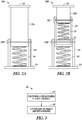
- FIG. 2A illustrates an example of a module 200A which includes shear pin 236A and energy absorber 240.
- module 200A includes first end 210 and second end 220. First end 210 and second end 220 are affixed to seat 50 (not shown in this figure) and support structure 150 (not shown in this figure). First end 210 is affixed to column 250A. As shown in the figure, column 250A is retained in a fixed position relative to receiver 230 by pin 236A.
- energy absorber 240 is disposed within receiver 230 between column 250A and second end 220. In the example shown, energy absorber 240 includes an idealized energy absorbing mechanism configured to oppose a compressive load exerted between column 250A and end 220.
- module 200A is configured to dissipate energy according to a predetermined profile based on shearing of pin 236A upon loading exceeding a predetermined threshold and thereafter to dissipate energy by compressing energy absorber 240.
- the idealized energy absorbing mechanism can include a compression spring, such as a coil spring.
- FIG. 2B illustrates an example of a module 200B which includes shear pin 236B, shear pin 236C, energy absorber 240, and energy absorber 270.
- Energy absorber 240 is positioned between end 220 and an end of intermediate section 260.
- Intermediate section 260 is configured to slidably engage with receiver 230.
- Energy absorber 240 dissipates energy following shearing of pin 236B.
- Energy absorber 270 is positioned between an end of column 250B and an end of intermediate section 260. In the example shown, energy absorber 270 abuts false bottom 280. False bottom 280 isolates energy absorber 270 and energy absorber 240 in the example shown.
- Pin 236C and energy absorber 270 are in series alignment relative to pin 236B and energy absorber 240.
- the energy absorbing profile can be tailored by selection of the spring rates and shear strength of the various elements.
- the shear strength of pin 236C can be configured to be different (greater or lesser) than the shear strength of pin 236B.
- the spring rate of energy absorber 240 can be configured to be different (greater or lesser) than the spring rate of energy absorber 270.
- FIG. 3 illustrates method 300 according to one example of the present subject matter.
- Method 300 includes, at 310, positioning a shear member in a seat assembly. Positioning a shear member can include placing a pin in a manner to retain two elements (such as a seat and a support structure) in fixed alignment unless loaded with a force exceeding a predetermined shear force. Upon exceeding the predetermined shear force, the shear member is configured to sever or fracture in a manner to allow relative movement between the two elements.
- Method 300 includes, at 320, configuring an energy absorbing member to control movement as to the two elements. The energy absorbing member is configured to absorb energy at a time after fracturing the shear member based on relative movement as to the two elements.
- the energy absorber can include a coil spring, or a leaf spring configured to absorb energy under a torsional or lineal displacement.
- the shear element can include an element configured to rupture or otherwise separate in a manner to allow unrestrained relative movement as to two elements.
- the shear element can include a pin, a drum (having a surface configured to rupture at a predetermined load), or a ball and socket arrangement that allows movement after overcoming a spring force.
- the number of shear elements and the number of energy absorbers is not limited.
- two shear pins can be configured for use with a single energy absorber.
- the diameter and profile of a shear pin can be tailored to shear at a predetermined load.
- Multiple shear elements can be arranged in a serial or parallel order.
- module 200A or module 200B is configured to replace leg 140 and associated elements of system 100 ( FIG. 1 ).
- more than one leg of seat 50 can be configured as described herein.
- seat 50 travels along a linear track, as shown in FIG. 1 .
- Other travel arrangements are also contemplated, including a curved path.
- leg 160 FIG. 1
- leg 140 can be configured to accommodate motion along an arc.
- Leg 140 can include a tubular structure. In other examples, leg 140 includes a formed channel, a square section, or other configuration.
- the shear pin and the energy absorbing mechanism can be configured to provide protection to an occupant ranging from the 5 th to the 95 th percentile male and female population.
- the present inventors also contemplate examples using any combination or permutation of those elements shown or described (or one or more aspects thereof), either with respect to a particular example (or one or more aspects thereof), or with respect to other examples (or one or more aspects thereof) shown or described herein, as long as they remain within the scope of protection as defined in the claims.
- the usage in this document controls.
Landscapes
- Engineering & Computer Science (AREA)
- Aviation & Aerospace Engineering (AREA)
- Transportation (AREA)
- Mechanical Engineering (AREA)
- Vibration Dampers (AREA)
- Seats For Vehicles (AREA)
Claims (15)
- Système comprenant :un organe de cisaillement (236A) configuré pour coupler une partie siège (50) à une structure de base (150) d'un véhicule, l'organe de cisaillement (236A) étant configuré pour soutenir une première charge sans rupture et configuré pour se déformer de manière non élastique sous une seconde charge, la seconde charge supérieure à la première charge ; etun absorbeur d'énergie (240) configuré pour être couplé à la partie siège (50) et couplé à la structure de base (150), l'absorbeur d'énergie (240) comprenant un ressort configuré pour absorber une énergie suite à une déformation de l'organe de cisaillement.
- Système selon la revendication 1, dans lequel l'organe de cisaillement (236A) comprend une goupille.
- Système selon la revendication 2, dans lequel la première charge et la seconde charge sont alignées selon un axe de charge et dans lequel la goupille a un axe aligné sensiblement perpendiculairement à l'axe de charge.
- Système selon l'une quelconque des revendications 1 à 3, dans lequel l'absorbeur d'énergie (240) inclut un limitateur (130) configurée pour restreindre le mouvement de la partie siège par rapport à la structure de base (150).
- Système selon la revendication 4, dans lequel le limitateur (130) comprend une glissière.
- Système selon l'une quelconque des revendications 1 à 5, dans lequel l'organe de cisaillement (236A) comprend un premier organe de cisaillement (236B) et un second organe de cisaillement (236C) ; l'absorbeur d'énergie (240) comprend un premier absorbeur d'énergie (240) comprenant un ressort et un second absorbeur d'énergie (270) comprenant un ressort ; le premier organe de cisaillement (236B) configuré pour soutenir une première charge prédéterminée sans rupture et configuré pour se cisailler sous une charge dépassant la première charge prédéterminée ; le premier absorbeur d'énergie (240) configuré pour absorber une énergie suite à une déformation du premier organe de cisaillement (236B) ; le second organe de cisaillement (236C) configuré pour soutenir une seconde charge prédéterminée sans rupture et configuré pour se cisailler sous une charge dépassant la seconde charge prédéterminée ; et le second absorbeur d'énergie (270) configuré pour absorber une énergie à la suite d'une déformation du second organe de cisaillement (236C).
- Procédé comprenant :positionner un organe de cisaillement (236A) dans un ensemble de siège (50), l'organe de cisaillement (236A) étant configuré pour soutenir une charge prédéterminée sans rupture et configuré pour se cisailler sous une charge dépassant la charge prédéterminée ; etconfigurer un organe absorbeur d'énergie (240) pour permettre un mouvement relatif entre l'ensemble de siège (50) et une structure (150), l'organe absorbeur d'énergie (240) comprenant un ressort configuré pour dissiper une énergie correspondant à la charge prédéterminée, suite à la déformation de l'organe de cisaillement.
- Procédé selon la revendication 7, dans lequel le positionnement de l'organe de cisaillement (236A) comprend l'agencement d'une goupille de cisaillement dans l'ensemble de siège (50).
- Procédé selon la revendication 7 ou la revendication 8, comprenant en outre la fourniture d'un ensemble de glissière pour commander le mouvement relatif.
- Procédé selon l'une quelconque des revendications 7 à 9, dans lequel le positionnement de l'organe de cisaillement (236A) comprend le positionnement d'un premier organe de cisaillement (236B) et d'un second organe de cisaillement (236B) ; et la configuration de l'absorbeur d'énergie (240) comprend la configuration d'un premier absorbeur d'énergie (240) comprenant un ressort et un second absorbeur d'énergie (270) comprenant un ressort ; le premier organe de cisaillement (236B) configuré pour soutenir une première charge prédéterminée sans rupture et configuré pour se cisailler sous une charge dépassant la première charge prédéterminée ; le premier absorbeur d'énergie (240) configuré pour absorber une énergie suite à une déformation du premier organe de cisaillement (236B) ; le second organe de cisaillement (236C) configuré pour soutenir une seconde charge prédéterminée sans rupture et configuré pour se cisailler sous une charge dépassant la seconde charge prédéterminée ; et le second absorbeur d'énergie (270) configuré pour absorber une énergie à la suite d'une déformation du second organe de cisaillement (236C).
- Système comprenant :un véhicule configuré pour transporter un occupant ;un ensemble de siège (50) configuré pour porter l'occupant,un ensemble de glissière (130) couplant le véhicule et couplant l'ensemble de siège (50), l'ensemble de glissière (130) étant configuré pour commander le mouvement de l'ensemble de siège (50) par rapport au véhicule ;un organe de cisaillement (236A) couplé à l'ensemble de glissière (130), dans lequel, lorsqu'il est soumis à une force inférieure à un niveau prédéterminé, l'organe de cisaillement (236A) limite le mouvement de l'ensemble de siège (50) par rapport au véhicule et dans lequel, lorsqu'il est soumis à une force supérieure au niveau prédéterminé, l'organe de cisaillement (236A) se rompt et permet le mouvement de l'ensemble de siège (50) par rapport au véhicule ; etun absorbeur d'énergie (240) couplé à l'ensemble de siège (50), l'absorbeur d'énergie (240) comprenant un ressort configuré pour dissiper une énergie sur la base d'un mouvement de l'ensemble de siège (50) par rapport au véhicule, suite à une déformation de l'organe de cisaillement.
- Système selon la revendication 11, dans lequel le véhicule comprend un véhicule aérospatial ou un véhicule terrestre.
- Système selon la revendication 11 ou la revendication 12, dans lequel l'ensemble de glissière (130) comprend au moins un guide et un canal.
- Système selon l'une quelconque des revendications 11 à 13, dans lequel l'organe de cisaillement (236A) comprend une goupille.
- Système selon l'une quelconque des revendications 11 à 14, dans lequel l'organe de cisaillement (236A) comprend un premier organe de cisaillement (236B) et un second organe de cisaillement (236B) ; l'absorbeur d'énergie (240) comprend un premier absorbeur d'énergie (240) comprenant un ressort et un second absorbeur d'énergie (270) comprenant un ressort ; le premier organe de cisaillement (236B) configuré pour soutenir une première charge prédéterminée sans rupture et configuré pour se cisailler sous une charge dépassant la première charge prédéterminée ; le premier absorbeur d'énergie (240) configuré pour absorber une énergie suite à une déformation du premier organe de cisaillement (236B) ; le second organe de cisaillement (236C) configuré pour soutenir une seconde charge prédéterminée sans rupture et configuré pour se cisailler sous une charge dépassant la seconde charge prédéterminée ; et le second absorbeur d'énergie (270) configuré pour absorber une énergie à la suite à une déformation du second organe de cisaillement (236C).
Applications Claiming Priority (2)
| Application Number | Priority Date | Filing Date | Title |
|---|---|---|---|
| US201161576748P | 2011-12-16 | 2011-12-16 | |
| PCT/US2012/069789 WO2013090744A1 (fr) | 2011-12-16 | 2012-12-14 | Mécanisme de siège absorbant l'énergie |
Publications (2)
| Publication Number | Publication Date |
|---|---|
| EP2790959A1 EP2790959A1 (fr) | 2014-10-22 |
| EP2790959B1 true EP2790959B1 (fr) | 2018-05-16 |
Family
ID=47520273
Family Applications (1)
| Application Number | Title | Priority Date | Filing Date |
|---|---|---|---|
| EP12812460.9A Not-in-force EP2790959B1 (fr) | 2011-12-16 | 2012-12-14 | Mécanisme de siège d'absorption d'énergie |
Country Status (3)
| Country | Link |
|---|---|
| US (2) | US9327623B2 (fr) |
| EP (1) | EP2790959B1 (fr) |
| WO (1) | WO2013090744A1 (fr) |
Families Citing this family (19)
| Publication number | Priority date | Publication date | Assignee | Title |
|---|---|---|---|---|
| EP2790959B1 (fr) | 2011-12-16 | 2018-05-16 | Wichita State University | Mécanisme de siège d'absorption d'énergie |
| US10272863B1 (en) * | 2014-10-31 | 2019-04-30 | Safe, Inc. | Structure and method for protecting a passenger during a crash |
| US20160121765A1 (en) * | 2014-10-31 | 2016-05-05 | Safe Inc. | Structure and method for protecting a passenger during a crash |
| EP3100902A3 (fr) | 2015-04-13 | 2017-02-22 | Survivability Solutions LLC | Systèmes de support et de fixation d'ensemble siège de véhicule |
| US10150392B2 (en) * | 2016-02-24 | 2018-12-11 | Ayyakannu Mani | Combat vehicle seat installation for protection of occupants from the effects of ground explosions |
| DE102017201356A1 (de) | 2017-01-27 | 2018-08-02 | Ford Global Technologies, Llc | Sitzträger für einen Fahrzeugsitz |
| US10166889B1 (en) | 2017-04-10 | 2019-01-01 | Armorworks Holdings, Inc. | Series mounted energy attenuator and spring damper |
| EP3609735B1 (fr) | 2017-04-13 | 2022-05-18 | Rheinmetall Protection Systems GmbH | Siège absorbant des chocs comprenant des organes d'amortissement montés au sol ou au plafond |
| DE102017112390A1 (de) | 2017-06-06 | 2018-12-06 | Dr. Ing. H.C. F. Porsche Aktiengesellschaft | Ladedose für ein elektrisch angetriebenes Fahrzeug |
| US20190359096A1 (en) * | 2018-05-22 | 2019-11-28 | Ami Industries, Inc. | Collapsible structure with varying stiffness-based energy attenuation system |
| US11427337B2 (en) | 2019-01-30 | 2022-08-30 | Goodrich Corporation | Radial slit disc energy attenuation system |
| US11110831B2 (en) * | 2019-02-25 | 2021-09-07 | Scott Coffman | Force absorbing vehicle seat mounting system |
| SE543787C2 (en) * | 2019-02-28 | 2021-07-20 | Mim Construction Ab | Security arrangement for a load carrying assembly |
| EP4053017B1 (fr) * | 2021-03-01 | 2024-07-31 | Autoflug GmbH | Dispositif d'absorption d'énergie pour un siège d'un véhicule et système de siège doté d'un tel dispositif d'absorption d'énergie |
| US11535129B1 (en) * | 2021-08-17 | 2022-12-27 | Honda Motor Co., Ltd. | Vehicle seat mounting bracket for energy attenuating member |
| US11794904B2 (en) | 2021-11-09 | 2023-10-24 | Ami Industries, Inc. | Compact rotorcraft seating assembly with non-linear bucket guide channels |
| US12565317B2 (en) | 2022-08-04 | 2026-03-03 | B/E Aerospace, Inc. | Helical connecting link and method for energy absorption using the same |
| US12351315B2 (en) * | 2022-11-14 | 2025-07-08 | Ami Industries, Inc. | Two-stage energy absorbing system for rotary-wing aircraft seats |
| US12552539B2 (en) | 2023-11-15 | 2026-02-17 | Ami Industries, Inc. | Method for automatic seat pan tilt |
Family Cites Families (19)
| Publication number | Priority date | Publication date | Assignee | Title |
|---|---|---|---|---|
| US4343488A (en) * | 1979-11-05 | 1982-08-10 | Allied Corporation | Seat belt system with reduced spooling |
| US5328234A (en) * | 1992-11-20 | 1994-07-12 | Ford Motor Company | Rotatable seat for vehicles |
| FR2719880B1 (fr) * | 1994-05-11 | 1996-06-07 | Messier Bugatti | Dispositif de sécurité à élément télescopique limiteur d'accélération, destiné à assurer la protection d'un système transporté à bord d'un véhicule en cas de choc. |
| US5957426A (en) * | 1997-04-10 | 1999-09-28 | Brodersen; Cole T. | Mechanical seat suspension with multiple position, lift-type height adjuster |
| US6170865B1 (en) * | 1999-01-23 | 2001-01-09 | Martin Barron | Electromagnetic car seat release upon deployment of vehicular air bag |
| US6742838B1 (en) * | 2003-03-19 | 2004-06-01 | Richard Swierczewski | Multifunction vehicle seat |
| US6637712B1 (en) * | 2002-05-17 | 2003-10-28 | Dura Global Technologies, Inc. | Automotive seat track lock mechanism with positive engagement |
| FR2862259B1 (fr) * | 2003-11-19 | 2006-01-13 | Renault Sas | Siege pour vehicule automobile, et vehicule automobile equipe d'un tel siege. |
| US7384067B2 (en) * | 2006-01-06 | 2008-06-10 | Autoliv Asp, Inc. | Rollover protection for motor vehicles |
| US8052211B2 (en) * | 2007-10-29 | 2011-11-08 | University Of Delaware | Anti-whiplash vehicle system with active head restraint |
| TR201909172T4 (tr) * | 2008-10-07 | 2019-07-22 | Mobius Prot Systems Ltd | Şok emici mekanizma, araç ve uçak koltukları için yolcuların ayaklarını koruma cihazı ve koltukta oturan kişiyi darbelere karşı koruma yöntemi. |
| US8469400B2 (en) | 2009-02-23 | 2013-06-25 | Amsafe, Inc. (Phoenix Group) | Seat harness pretensioner |
| US8162374B2 (en) * | 2009-03-11 | 2012-04-24 | Arcca, Incorporated | Dual stage variable load energy absorber for vehicle seating |
| DE102009040010B4 (de) * | 2009-07-02 | 2019-02-14 | Grammer Aktiengesellschaft | Veränderung der Federkraft mittels Hebel |
| DE102010026569B4 (de) * | 2009-07-28 | 2014-03-27 | Grammer Aktiengesellschaft | Regelungseinrichtung zur Reduzierung einer Schwingungsbewegung einer federkraftbeaufschlagten schwingenden Vorrichtung |
| US8398141B2 (en) * | 2010-12-10 | 2013-03-19 | Honda Motor Co., Ltd. | Vehicle seating arrangement for a vehicle seat including a cantilevered section |
| US8973693B2 (en) * | 2011-02-11 | 2015-03-10 | Polaris Industries Inc. | Side by side all terrain vehicle |
| US20130033056A1 (en) * | 2011-08-05 | 2013-02-07 | Tunis Iii George C | Energy absorbing system for blast mitigation of support elements such as suspended seats or stretchers in military vehicles |
| EP2790959B1 (fr) | 2011-12-16 | 2018-05-16 | Wichita State University | Mécanisme de siège d'absorption d'énergie |
-
2012
- 2012-12-14 EP EP12812460.9A patent/EP2790959B1/fr not_active Not-in-force
- 2012-12-14 US US14/365,059 patent/US9327623B2/en active Active
- 2012-12-14 WO PCT/US2012/069789 patent/WO2013090744A1/fr not_active Ceased
-
2016
- 2016-04-28 US US15/141,608 patent/US9981574B2/en active Active
Non-Patent Citations (1)
| Title |
|---|
| None * |
Also Published As
| Publication number | Publication date |
|---|---|
| US9981574B2 (en) | 2018-05-29 |
| EP2790959A1 (fr) | 2014-10-22 |
| US20140339866A1 (en) | 2014-11-20 |
| US9327623B2 (en) | 2016-05-03 |
| WO2013090744A1 (fr) | 2013-06-20 |
| US20170028882A1 (en) | 2017-02-02 |
Similar Documents
| Publication | Publication Date | Title |
|---|---|---|
| US9981574B2 (en) | Energy absorbing seat mechanism | |
| EP2576284B1 (fr) | Siège d'atténuation des effets d'explosion | |
| EP2342475B1 (fr) | Mécanisme d'amortissement de choc, dispositif de protection de pieds d' un occupant de siège pour sieges de véhicule et d'aéronef, et procédé de protection d'un occupant de siege contre les impacts | |
| US9382008B2 (en) | Anti-crash seat and an aircraft | |
| US8342300B2 (en) | Energy adsorber device that adapts automatically to the weight it supports | |
| US10414501B2 (en) | Seat back breakover with dynamically triggered actuator | |
| US7155747B2 (en) | Head stabilizing system | |
| US5538117A (en) | Safety device for a system transported on board a vehicle, in particular an aircraft | |
| Desjardins | The evolution of energy absorption systems for crashworthy helicopter seats | |
| US10279913B2 (en) | Consolidated seat back breakover mechanism | |
| EP4054892A1 (fr) | Protection de siège de sécurité contre les chocs latéraux | |
| WO2013111167A1 (fr) | Dispositif de sécurité destiné à un siège de véhicule, cadre pour ledit siège et véhicule équipé dudit dispositif | |
| CN105940237B (zh) | 碰撞缓冲装置 | |
| US20110260000A1 (en) | Energy absorber system for an undercarriage, and an aircraft provided with said energy absorber system | |
| WO2006018721A1 (fr) | Dispositif de dissipation d'energie de choc | |
| US20180339776A1 (en) | Inertia reel mounts and mounting arrangements | |
| US6450449B1 (en) | Crashworthy seat | |
| EP2848459B1 (fr) | Dispositif de mise en mémoire tampon de ceinture de sécurité et siège de sécurité pour véhicule comportant ledit dispositif | |
| IL289818A (en) | A two-function mechanism that enables two modes of operation of a vehicle seat | |
| Olivares | Energy absorbing seat mechanism | |
| JP6180907B2 (ja) | 負荷支持構造どうしを急速に分離させるための機構 | |
| US20140292045A1 (en) | Mechanism for Increasing the Distance Traveled During a Forceful Change in Velocity | |
| EP4253236A2 (fr) | Dispositifs de réduction de hic | |
| Del Prete et al. | Design for Manufacturing for Energy Absorption Systems | |
| NZ724821A (en) | Assembly for energy absorption in an overload event |
Legal Events
| Date | Code | Title | Description |
|---|---|---|---|
| PUAI | Public reference made under article 153(3) epc to a published international application that has entered the european phase |
Free format text: ORIGINAL CODE: 0009012 |
|
| 17P | Request for examination filed |
Effective date: 20140715 |
|
| AK | Designated contracting states |
Kind code of ref document: A1 Designated state(s): AL AT BE BG CH CY CZ DE DK EE ES FI FR GB GR HR HU IE IS IT LI LT LU LV MC MK MT NL NO PL PT RO RS SE SI SK SM TR |
|
| DAX | Request for extension of the european patent (deleted) | ||
| GRAP | Despatch of communication of intention to grant a patent |
Free format text: ORIGINAL CODE: EPIDOSNIGR1 |
|
| INTG | Intention to grant announced |
Effective date: 20171124 |
|
| GRAS | Grant fee paid |
Free format text: ORIGINAL CODE: EPIDOSNIGR3 |
|
| GRAA | (expected) grant |
Free format text: ORIGINAL CODE: 0009210 |
|
| AK | Designated contracting states |
Kind code of ref document: B1 Designated state(s): AL AT BE BG CH CY CZ DE DK EE ES FI FR GB GR HR HU IE IS IT LI LT LU LV MC MK MT NL NO PL PT RO RS SE SI SK SM TR |
|
| REG | Reference to a national code |
Ref country code: GB Ref legal event code: FG4D |
|
| REG | Reference to a national code |
Ref country code: CH Ref legal event code: EP |
|
| REG | Reference to a national code |
Ref country code: IE Ref legal event code: FG4D |
|
| REG | Reference to a national code |
Ref country code: DE Ref legal event code: R096 Ref document number: 602012046445 Country of ref document: DE |
|
| REG | Reference to a national code |
Ref country code: AT Ref legal event code: REF Ref document number: 999235 Country of ref document: AT Kind code of ref document: T Effective date: 20180615 |
|
| REG | Reference to a national code |
Ref country code: NL Ref legal event code: MP Effective date: 20180516 |
|
| REG | Reference to a national code |
Ref country code: LT Ref legal event code: MG4D |
|
| PG25 | Lapsed in a contracting state [announced via postgrant information from national office to epo] |
Ref country code: SE Free format text: LAPSE BECAUSE OF FAILURE TO SUBMIT A TRANSLATION OF THE DESCRIPTION OR TO PAY THE FEE WITHIN THE PRESCRIBED TIME-LIMIT Effective date: 20180516 Ref country code: ES Free format text: LAPSE BECAUSE OF FAILURE TO SUBMIT A TRANSLATION OF THE DESCRIPTION OR TO PAY THE FEE WITHIN THE PRESCRIBED TIME-LIMIT Effective date: 20180516 Ref country code: LT Free format text: LAPSE BECAUSE OF FAILURE TO SUBMIT A TRANSLATION OF THE DESCRIPTION OR TO PAY THE FEE WITHIN THE PRESCRIBED TIME-LIMIT Effective date: 20180516 Ref country code: NO Free format text: LAPSE BECAUSE OF FAILURE TO SUBMIT A TRANSLATION OF THE DESCRIPTION OR TO PAY THE FEE WITHIN THE PRESCRIBED TIME-LIMIT Effective date: 20180816 Ref country code: FI Free format text: LAPSE BECAUSE OF FAILURE TO SUBMIT A TRANSLATION OF THE DESCRIPTION OR TO PAY THE FEE WITHIN THE PRESCRIBED TIME-LIMIT Effective date: 20180516 Ref country code: BG Free format text: LAPSE BECAUSE OF FAILURE TO SUBMIT A TRANSLATION OF THE DESCRIPTION OR TO PAY THE FEE WITHIN THE PRESCRIBED TIME-LIMIT Effective date: 20180816 |
|
| PG25 | Lapsed in a contracting state [announced via postgrant information from national office to epo] |
Ref country code: RS Free format text: LAPSE BECAUSE OF FAILURE TO SUBMIT A TRANSLATION OF THE DESCRIPTION OR TO PAY THE FEE WITHIN THE PRESCRIBED TIME-LIMIT Effective date: 20180516 Ref country code: HR Free format text: LAPSE BECAUSE OF FAILURE TO SUBMIT A TRANSLATION OF THE DESCRIPTION OR TO PAY THE FEE WITHIN THE PRESCRIBED TIME-LIMIT Effective date: 20180516 Ref country code: NL Free format text: LAPSE BECAUSE OF FAILURE TO SUBMIT A TRANSLATION OF THE DESCRIPTION OR TO PAY THE FEE WITHIN THE PRESCRIBED TIME-LIMIT Effective date: 20180516 Ref country code: LV Free format text: LAPSE BECAUSE OF FAILURE TO SUBMIT A TRANSLATION OF THE DESCRIPTION OR TO PAY THE FEE WITHIN THE PRESCRIBED TIME-LIMIT Effective date: 20180516 Ref country code: GR Free format text: LAPSE BECAUSE OF FAILURE TO SUBMIT A TRANSLATION OF THE DESCRIPTION OR TO PAY THE FEE WITHIN THE PRESCRIBED TIME-LIMIT Effective date: 20180817 |
|
| REG | Reference to a national code |
Ref country code: AT Ref legal event code: MK05 Ref document number: 999235 Country of ref document: AT Kind code of ref document: T Effective date: 20180516 |
|
| PG25 | Lapsed in a contracting state [announced via postgrant information from national office to epo] |
Ref country code: SK Free format text: LAPSE BECAUSE OF FAILURE TO SUBMIT A TRANSLATION OF THE DESCRIPTION OR TO PAY THE FEE WITHIN THE PRESCRIBED TIME-LIMIT Effective date: 20180516 Ref country code: EE Free format text: LAPSE BECAUSE OF FAILURE TO SUBMIT A TRANSLATION OF THE DESCRIPTION OR TO PAY THE FEE WITHIN THE PRESCRIBED TIME-LIMIT Effective date: 20180516 Ref country code: PL Free format text: LAPSE BECAUSE OF FAILURE TO SUBMIT A TRANSLATION OF THE DESCRIPTION OR TO PAY THE FEE WITHIN THE PRESCRIBED TIME-LIMIT Effective date: 20180516 Ref country code: DK Free format text: LAPSE BECAUSE OF FAILURE TO SUBMIT A TRANSLATION OF THE DESCRIPTION OR TO PAY THE FEE WITHIN THE PRESCRIBED TIME-LIMIT Effective date: 20180516 Ref country code: AT Free format text: LAPSE BECAUSE OF FAILURE TO SUBMIT A TRANSLATION OF THE DESCRIPTION OR TO PAY THE FEE WITHIN THE PRESCRIBED TIME-LIMIT Effective date: 20180516 Ref country code: RO Free format text: LAPSE BECAUSE OF FAILURE TO SUBMIT A TRANSLATION OF THE DESCRIPTION OR TO PAY THE FEE WITHIN THE PRESCRIBED TIME-LIMIT Effective date: 20180516 Ref country code: CZ Free format text: LAPSE BECAUSE OF FAILURE TO SUBMIT A TRANSLATION OF THE DESCRIPTION OR TO PAY THE FEE WITHIN THE PRESCRIBED TIME-LIMIT Effective date: 20180516 |
|
| REG | Reference to a national code |
Ref country code: DE Ref legal event code: R097 Ref document number: 602012046445 Country of ref document: DE |
|
| PG25 | Lapsed in a contracting state [announced via postgrant information from national office to epo] |
Ref country code: SM Free format text: LAPSE BECAUSE OF FAILURE TO SUBMIT A TRANSLATION OF THE DESCRIPTION OR TO PAY THE FEE WITHIN THE PRESCRIBED TIME-LIMIT Effective date: 20180516 |
|
| PLBE | No opposition filed within time limit |
Free format text: ORIGINAL CODE: 0009261 |
|
| STAA | Information on the status of an ep patent application or granted ep patent |
Free format text: STATUS: NO OPPOSITION FILED WITHIN TIME LIMIT |
|
| 26N | No opposition filed |
Effective date: 20190219 |
|
| PG25 | Lapsed in a contracting state [announced via postgrant information from national office to epo] |
Ref country code: SI Free format text: LAPSE BECAUSE OF FAILURE TO SUBMIT A TRANSLATION OF THE DESCRIPTION OR TO PAY THE FEE WITHIN THE PRESCRIBED TIME-LIMIT Effective date: 20180516 |
|
| REG | Reference to a national code |
Ref country code: CH Ref legal event code: PL |
|
| PG25 | Lapsed in a contracting state [announced via postgrant information from national office to epo] |
Ref country code: MC Free format text: LAPSE BECAUSE OF FAILURE TO SUBMIT A TRANSLATION OF THE DESCRIPTION OR TO PAY THE FEE WITHIN THE PRESCRIBED TIME-LIMIT Effective date: 20180516 Ref country code: LU Free format text: LAPSE BECAUSE OF NON-PAYMENT OF DUE FEES Effective date: 20181214 |
|
| REG | Reference to a national code |
Ref country code: IE Ref legal event code: MM4A |
|
| REG | Reference to a national code |
Ref country code: BE Ref legal event code: MM Effective date: 20181231 |
|
| PG25 | Lapsed in a contracting state [announced via postgrant information from national office to epo] |
Ref country code: IE Free format text: LAPSE BECAUSE OF NON-PAYMENT OF DUE FEES Effective date: 20181214 |
|
| PG25 | Lapsed in a contracting state [announced via postgrant information from national office to epo] |
Ref country code: AL Free format text: LAPSE BECAUSE OF FAILURE TO SUBMIT A TRANSLATION OF THE DESCRIPTION OR TO PAY THE FEE WITHIN THE PRESCRIBED TIME-LIMIT Effective date: 20180516 Ref country code: BE Free format text: LAPSE BECAUSE OF NON-PAYMENT OF DUE FEES Effective date: 20181231 |
|
| PG25 | Lapsed in a contracting state [announced via postgrant information from national office to epo] |
Ref country code: CH Free format text: LAPSE BECAUSE OF NON-PAYMENT OF DUE FEES Effective date: 20181231 Ref country code: LI Free format text: LAPSE BECAUSE OF NON-PAYMENT OF DUE FEES Effective date: 20181231 |
|
| PG25 | Lapsed in a contracting state [announced via postgrant information from national office to epo] |
Ref country code: MT Free format text: LAPSE BECAUSE OF NON-PAYMENT OF DUE FEES Effective date: 20181214 |
|
| PGFP | Annual fee paid to national office [announced via postgrant information from national office to epo] |
Ref country code: IT Payment date: 20191219 Year of fee payment: 8 Ref country code: FR Payment date: 20191226 Year of fee payment: 8 |
|
| PG25 | Lapsed in a contracting state [announced via postgrant information from national office to epo] |
Ref country code: TR Free format text: LAPSE BECAUSE OF FAILURE TO SUBMIT A TRANSLATION OF THE DESCRIPTION OR TO PAY THE FEE WITHIN THE PRESCRIBED TIME-LIMIT Effective date: 20180516 |
|
| PGFP | Annual fee paid to national office [announced via postgrant information from national office to epo] |
Ref country code: GB Payment date: 20200102 Year of fee payment: 8 Ref country code: DE Payment date: 20191231 Year of fee payment: 8 |
|
| PG25 | Lapsed in a contracting state [announced via postgrant information from national office to epo] |
Ref country code: PT Free format text: LAPSE BECAUSE OF FAILURE TO SUBMIT A TRANSLATION OF THE DESCRIPTION OR TO PAY THE FEE WITHIN THE PRESCRIBED TIME-LIMIT Effective date: 20180516 |
|
| PG25 | Lapsed in a contracting state [announced via postgrant information from national office to epo] |
Ref country code: CY Free format text: LAPSE BECAUSE OF FAILURE TO SUBMIT A TRANSLATION OF THE DESCRIPTION OR TO PAY THE FEE WITHIN THE PRESCRIBED TIME-LIMIT Effective date: 20180516 Ref country code: MK Free format text: LAPSE BECAUSE OF NON-PAYMENT OF DUE FEES Effective date: 20180516 Ref country code: HU Free format text: LAPSE BECAUSE OF FAILURE TO SUBMIT A TRANSLATION OF THE DESCRIPTION OR TO PAY THE FEE WITHIN THE PRESCRIBED TIME-LIMIT; INVALID AB INITIO Effective date: 20121214 |
|
| PG25 | Lapsed in a contracting state [announced via postgrant information from national office to epo] |
Ref country code: IS Free format text: LAPSE BECAUSE OF FAILURE TO SUBMIT A TRANSLATION OF THE DESCRIPTION OR TO PAY THE FEE WITHIN THE PRESCRIBED TIME-LIMIT Effective date: 20180916 |
|
| REG | Reference to a national code |
Ref country code: DE Ref legal event code: R119 Ref document number: 602012046445 Country of ref document: DE |
|
| GBPC | Gb: european patent ceased through non-payment of renewal fee |
Effective date: 20201214 |
|
| PG25 | Lapsed in a contracting state [announced via postgrant information from national office to epo] |
Ref country code: IT Free format text: LAPSE BECAUSE OF NON-PAYMENT OF DUE FEES Effective date: 20201214 Ref country code: FR Free format text: LAPSE BECAUSE OF NON-PAYMENT OF DUE FEES Effective date: 20201231 |
|
| PG25 | Lapsed in a contracting state [announced via postgrant information from national office to epo] |
Ref country code: GB Free format text: LAPSE BECAUSE OF NON-PAYMENT OF DUE FEES Effective date: 20201214 Ref country code: DE Free format text: LAPSE BECAUSE OF NON-PAYMENT OF DUE FEES Effective date: 20210701 |