EP2792425A1 - Method and device for cleaning the inside of a fluid tank - Google Patents
Method and device for cleaning the inside of a fluid tank Download PDFInfo
- Publication number
- EP2792425A1 EP2792425A1 EP14163059.0A EP14163059A EP2792425A1 EP 2792425 A1 EP2792425 A1 EP 2792425A1 EP 14163059 A EP14163059 A EP 14163059A EP 2792425 A1 EP2792425 A1 EP 2792425A1
- Authority
- EP
- European Patent Office
- Prior art keywords
- fluid
- tank
- fluid tank
- primary
- supplied
- Prior art date
- Legal status (The legal status is an assumption and is not a legal conclusion. Google has not performed a legal analysis and makes no representation as to the accuracy of the status listed.)
- Granted
Links
- 239000012530 fluid Substances 0.000 title claims abstract description 265
- 238000004140 cleaning Methods 0.000 title claims abstract description 35
- 238000000034 method Methods 0.000 title claims abstract description 23
- 239000000356 contaminant Substances 0.000 claims abstract description 19
- 238000007599 discharging Methods 0.000 claims abstract description 10
- 230000002349 favourable effect Effects 0.000 claims abstract description 8
- 238000009434 installation Methods 0.000 claims abstract 6
- 239000007789 gas Substances 0.000 claims description 58
- 238000002485 combustion reaction Methods 0.000 claims description 15
- 230000003750 conditioning effect Effects 0.000 claims description 10
- 238000011010 flushing procedure Methods 0.000 claims description 7
- 238000006243 chemical reaction Methods 0.000 claims description 4
- 238000010438 heat treatment Methods 0.000 claims description 4
- 239000002918 waste heat Substances 0.000 claims description 3
- 230000006835 compression Effects 0.000 claims 2
- 238000007906 compression Methods 0.000 claims 2
- 230000005540 biological transmission Effects 0.000 claims 1
- IJGRMHOSHXDMSA-UHFFFAOYSA-N Atomic nitrogen Chemical compound N#N IJGRMHOSHXDMSA-UHFFFAOYSA-N 0.000 description 21
- 229910001873 dinitrogen Inorganic materials 0.000 description 13
- 239000002737 fuel gas Substances 0.000 description 5
- 238000010926 purge Methods 0.000 description 5
- 229910052757 nitrogen Inorganic materials 0.000 description 4
- 239000007788 liquid Substances 0.000 description 3
- KAKZBPTYRLMSJV-UHFFFAOYSA-N Butadiene Chemical compound C=CC=C KAKZBPTYRLMSJV-UHFFFAOYSA-N 0.000 description 2
- PMPVIKIVABFJJI-UHFFFAOYSA-N Cyclobutane Chemical compound C1CCC1 PMPVIKIVABFJJI-UHFFFAOYSA-N 0.000 description 2
- VQTUBCCKSQIDNK-UHFFFAOYSA-N Isobutene Chemical compound CC(C)=C VQTUBCCKSQIDNK-UHFFFAOYSA-N 0.000 description 2
- ATUOYWHBWRKTHZ-UHFFFAOYSA-N Propane Chemical compound CCC ATUOYWHBWRKTHZ-UHFFFAOYSA-N 0.000 description 2
- QQONPFPTGQHPMA-UHFFFAOYSA-N Propene Chemical compound CC=C QQONPFPTGQHPMA-UHFFFAOYSA-N 0.000 description 2
- 230000000712 assembly Effects 0.000 description 2
- 238000000429 assembly Methods 0.000 description 2
- NNPPMTNAJDCUHE-UHFFFAOYSA-N isobutane Chemical compound CC(C)C NNPPMTNAJDCUHE-UHFFFAOYSA-N 0.000 description 2
- 238000012423 maintenance Methods 0.000 description 2
- 238000007726 management method Methods 0.000 description 2
- 238000003860 storage Methods 0.000 description 2
- 238000004220 aggregation Methods 0.000 description 1
- 230000002776 aggregation Effects 0.000 description 1
- 239000003225 biodiesel Substances 0.000 description 1
- 239000001273 butane Substances 0.000 description 1
- 230000001143 conditioned effect Effects 0.000 description 1
- 239000002283 diesel fuel Substances 0.000 description 1
- 230000000694 effects Effects 0.000 description 1
- 238000004880 explosion Methods 0.000 description 1
- 239000000295 fuel oil Substances 0.000 description 1
- 239000003502 gasoline Substances 0.000 description 1
- 239000011261 inert gas Substances 0.000 description 1
- 239000001282 iso-butane Substances 0.000 description 1
- 239000000203 mixture Substances 0.000 description 1
- IJDNQMDRQITEOD-UHFFFAOYSA-N n-butane Chemical compound CCCC IJDNQMDRQITEOD-UHFFFAOYSA-N 0.000 description 1
- OFBQJSOFQDEBGM-UHFFFAOYSA-N n-pentane Natural products CCCCC OFBQJSOFQDEBGM-UHFFFAOYSA-N 0.000 description 1
- 150000002894 organic compounds Chemical class 0.000 description 1
- 239000001294 propane Substances 0.000 description 1
- 238000011084 recovery Methods 0.000 description 1
- 238000010792 warming Methods 0.000 description 1
- XLYOFNOQVPJJNP-UHFFFAOYSA-N water Substances O XLYOFNOQVPJJNP-UHFFFAOYSA-N 0.000 description 1
Images

Classifications
-
- B—PERFORMING OPERATIONS; TRANSPORTING
- B08—CLEANING
- B08B—CLEANING IN GENERAL; PREVENTION OF FOULING IN GENERAL
- B08B9/00—Cleaning hollow articles by methods or apparatus specially adapted thereto
- B08B9/08—Cleaning containers, e.g. tanks
Definitions
- the invention relates to a method for internally cleaning a fluid tank having a connection for supplying fluid and a connection for discharging fluid, in which a primary fluid is introduced through the connection for the supply of fluid into the fluid tank, and through which connection for discharging fluid from the fluid tank, a secondary fluid in the form of fluid residues accommodated in the fluid tank and / or primary fluid charged with such fluid residues or contaminants is removed.
- the invention relates to a system for internally cleaning a fluid delivery port and a fluid discharge port, which has a conduit connectable to the fluid supply port for supplying a primary fluid into the fluid tank, and a conduit connectable to the fluid discharge port for discharging a secondary fluid in the form of fluid residues received in the fluid tank and / or primary fluid impinged upon such fluid residues or contaminants.
- a fluid tank means a closed container for the storage, storage and / or transport of gaseous and / or liquid media, such as e.g. Propane, butane, butadiene, propene, isobutane, isobutene, cyclobutane, gasoline or diesel fuel, biodiesel, fuel oil, cyclobutane, mixtures of these media, or other volatile, organic compounds containing or consisting of these fluids or other combustibles containing fluids.
- gaseous and / or liquid media such as e.g. Propane, butane, butadiene, propene, isobutane, isobutene, cyclobutane, gasoline or diesel fuel, biodiesel, fuel oil, cyclobutane, mixtures of these media, or other volatile, organic compounds containing or consisting of these fluids or other combustibles containing fluids.
- fluid cleaning Prior to performing maintenance and safety checks on a fluid tank, as well as to prepare for accommodating particular varying different fluids, fluid cleaning requires regular internal cleaning.
- the object of the invention is to provide a method for the internal cleaning of fluid tanks, which allows a cost-effective internal cleaning of fluid tanks, and to provide a system for the internal cleaning of fluid tanks, which can be operated with low operating costs.
- This object is achieved, on the one hand, by a method for cleaning internal fluid tanks of the type mentioned in the introduction, in which the primary fluid supplied to the fluid tank is heated to a process temperature which is favorable for the internal cleaning of the fluid tank.
- this object is achieved by a plant of the type mentioned, which contains a conditioning device for heating the primary fluid supplied to the fluid tank to a favorable for the internal cleaning of the fluid tank process temperature.
- gaseous primary fluid for purging such as nitrogen
- tank volumes which is often in the order of 20m 3
- very large gas quantities of 700m 3 or more needed which leads to considerable costs.
- an idea of the invention is also to heat the primary fluid used for internally cleaning fluid tanks before it is introduced into the fluid tank in order to reduce the amount of primary fluid required for flushing a fluid tank. Moreover, it is an idea of the invention to recover the energy needed to heat the primary fluid from secondary fluid received in the fluid tanks and contaminants removed from the fluid tanks.
- the secondary fluid discharged from a fluid tank during purging to a means for chemically reacting the secondary fluid to release heat to transfer the heat released therein at least partially to the primary fluid supplied to the fluid tank.
- the means for the chemical reaction of the secondary fluid may e.g. a burner in which the secondary fluid is burned with another combustible fluid.
- the burner is integrated in a preferably designed as a micro gas turbine turbine system and generates a hot gas stream, which is acted upon for generating kinetic energy, a gas turbine, which is coupled in motion with a mechanical energy consumer.
- the thermal energy contained in the exhaust gas flow of the gas turbine can then be transferred, for example, in the conditioning device at least partially to the primary fluid supplied to the fluid tank.
- An idea of the invention is therefore also to use a turbine system, in particular a micro gas turbine for cleaning or flushing a fluid tank with a primary fluid, wherein the turbine system comprises a burner and a compressor coupled to a gas turbine.
- the burner is supplied with a secondary fluid which consists of fluid residues accommodated in the fluid tank and / or primary fluid charged with such fluid residues or contaminants, and the exhaust gas released by the turbine system is supplied to a conditioning device for conditioning the primary fluid.
- the mechanical energy consumer is a compressor for compressing the combustion air supplied to the burner, wherein the combustion air compressed by the compressor thermal Energy is transferred from the exhaust stream.
- the mechanical energy consumer may alternatively or additionally also be an electrical generator which generates electrical current.
- the conduit for the discharge of secondary fluid from a fluid tank communicates with the conduit for supplying primary fluid into the fluid tank to re-supply the secondary fluid discharged from the fluid tank to the fluid tank.
- the conduit for the discharge of secondary fluid from a fluid tank communicates with the conduit for supplying primary fluid into the fluid tank to re-supply the secondary fluid discharged from the fluid tank to the fluid tank.
- the primary fluid used for rinsing a fluid tank can be conditioned to a process temperature which is favorable for the cleaning.
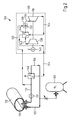
- the in the Fig. 1 shown plant 10 is used for the interior cleaning of a fluid tank 12, for example, mounted on a substructure in a tanker truck or integrated into a railway tank car.
- the fluid tank 12 has a connection 14 for the supply of fluid into the interior 16. Through a connection 18 of the fluid tank 12, it is possible to remove fluid from the interior 16.
- a nitrogen-filled pressure vessel 20 In the plant 10 there is a nitrogen-filled pressure vessel 20.
- the pressure vessel 20 can be connected to the fluid tank 12 via a connection 22 via the connection 14. From the pressure vessel 20 may in the fluid tank 12 through the conduit 22 in this manner as a primary fluid nitrogen gas are supplied to flush the interior 24 of the fluid tank 12 therewith.
- the nitrogen gas from the pressure vessel 20 in the plant 10 serves as a primary fluid for the fluid tank 12.
- a conveying unit configured as a pump or a compressor be provided, which is arranged in the line 22 between the pressure vessel 20 and the heat exchanger 48 or between the heat exchanger 48 and the fluid tank 12.
- the system 10 includes a micro gas turbine formed turbine system 26 with a burner 28. Via a line 30, which can be connected to the terminal 18 of the fluid tank 12, it is possible, the burner 28 in the turbine system 26 with fluid residues or polluted nitrogen gas as to supply a secondary fluid from the fluid tank 12.
- the plant 10 preferably, but not necessarily, includes a suction conveyor unit 31 designed as a compressor or pump.
- the burner 28 has a combustion chamber 32, in which the nitrogen gas charged with fluid residues or contaminants from the fluid tank 12 is burned with a fuel gas supplied from the outside and with combustion air.
- the burner 28 is for this purpose preferably designed as a so-called two-stage burner, which has a pilot stage as a first burner stage, in which the fuel gas is supplied, and as a second burner stage has a main stage, in which introduced the pressurized with fluid residues or contaminants nitrogen gas is to burn it there in a burner flame generated by the pilot stage.
- the burner 28 is for burning fluid residue or contaminants from the fluid tank 12 can also be a burner which burns nitrogen gas charged with fluid residues or contaminants without supplying additional fuel gas. In this case, however, it must be ensured that the fluid residues and contaminants in the nitrogen gas from the fluid tank 12 have combustion characteristics at least approximately corresponding to the combustion characteristics of fuel gas.
- the burner 28 thereby generates a hot gas jet, which is conducted via a hot gas duct 34 to a gas turbine 36.
- a gas turbine 36 the thermal energy of the hot gas generated by the burner 28 is converted into kinetic energy, which is then transferred to a compressor 38 motion-coupled to the gas turbine and an electric generator 40.
- the compressor is for compressing intake air which is supplied to the burner 28 through an intake air passage 42.
- electrical energy can be provided for a not further illustrated line network with electrical consumers.
- the exhaust gas of the gas turbine 36 is guided through an exhaust passage 44.
- the turbine system 26 includes a heat exchanger 46 that transfers heat from the exhaust gas of the gas turbine 36 to the compressed combustion air supplied to the burner 28.
- the exhaust passage 42 of the turbine system 26 is connected to a heat exchanger 48.
- the heat exchanger 48 is for conditioning nitrogen gas from the pressure vessel 20, which is supplied through the conduit 22 to the fluid tank 12 for purging from the interior thereof.
- the heat exchanger 48 is designed for heating nitrogen gas supplied from the pressure vessel 20. By means of the heat exchanger 48, it is possible to heat the nitrogen gas from the pressure vessel 20 from the ambient temperature up to 600 ° C.
- a fluid tank 12 having a large internal volume such as rail tank cars, tank trucks and ships fluid tanks, has interior volumes of up to 700m 3 are not uncommon, can be rinsed.
- the conditioning of the introduced into a fluid tank 12 primary fluid thereby not only causes dissolved in the interior of a fluid tank 12 contaminants, but also that in a fluid tank 12 recorded residual fluid swirled not only with the primary fluid, but by the heat transfer mostly in one gaseous state of aggregation can be transferred.
- Burner 28 thus acts as a means for chemically reacting secondary fluid in the form of primary fluid and residual fluid and contaminants from fluid tank 12 to release heat.
- the structure of the plant 100 in Fig. 2 corresponds basically to the structure of the system 10 Fig. 1 , Assemblies of the plant 100 in Fig. 2 , which are to assemblies in the Appendix 10 from in Fig. 1 are identical in the Fig. 2 in terms of the Fig. 1 numbers increased by the number 100 as reference numerals.
- a conduit section 150 which connects the secondary fluid discharge line 130 from the fluid tank 112 to the primary fluid supply line 122 in the fluid tank 112.
- the primary fluid can be partially circulated through the fluid tank 112, so that it passes through it several times.
- the Saug bankiki 131 instead of the Saug bankong 131 or additionally be provided for this in the line 122 designed as a pump or compressor stage pressure conveying unit.
- the hot exhaust gas of the turbine system 26, 126 in the systems 10, 100 can also be used to heat the fluid tank 12, 112 to be cleaned from the outside.
- the invention relates to a method for interior cleaning of a connection 14, 18 for the supply of fluid and a connection 14, 18 for the removal of fluid having fluid tank 12, 112, in which through the connection 14, 18 for the Feeding fluid into the fluid tank 12, 112 primary fluid is introduced.
- the port (14, 18) for discharging fluid from the fluid tank 12, 112 secondary fluid in the form of fluid contained in the fluid tank 12, 112 and / or primary fluid loaded with such fluid residue or contaminant is used as a secondary fluid dissipated.
- the primary fluid supplied to the fluid tank 12, 112 is heated to a process temperature which is favorable for the internal cleaning of the fluid tank 12, 112.
Landscapes
- Engineering & Computer Science (AREA)
- Mechanical Engineering (AREA)
- Cleaning In General (AREA)
Abstract
Verfahren und Anlage zum Innenreinigen eines einen Anschluss (14, 18) für das Zuführen von Fluid und einen Anschluss (14, 18) für das Abführen von Fluid aufweisenden Fluidtanks (12), bei dem durch den Anschluss (14, 18) für das Zuführen von Fluid in den Fluidtank (12) Primärfluid eingeleitet wird. Durch das Verfahren wird bei dem durch den Anschluss (14, 18) für das Abführen von Fluid aus dem Fluidtank (12) Sekundärfluid in Form von in dem Fluidtank (12) aufgenommenen Fluidresten und/oder mit solchen Fluidresten oder Schmutzstoffen beaufschlagtem Primärfluid abgeführt. Das dem Fluidtank (12) zugeführte Primärfluid wird auf eine für das Innenreinigen des Fluidtanks (12) günstige Prozesstemperatur erwärmt.Method and installation for internally cleaning a fluid tank (12) having a connection (14, 18) for the supply of fluid and a connection (14, 18) for the removal of fluid, in which the connection (14, 18) for the supply from fluid into the fluid tank (12) primary fluid is introduced. By means of the method, secondary fluid in the form of fluid residues accommodated in the fluid tank (12) and / or primary fluid charged with such fluid residues or contaminants is discharged through the connection (14, 18) for discharging fluid from the fluid tank (12). The primary fluid supplied to the fluid tank (12) is heated to a process temperature which is favorable for internally cleaning the fluid tank (12).
Description
Die Erfindung betrifft ein Verfahren zum Innenreinigen eines einen Anschluss für das Zuführen von Fluid und einen Anschluss für das Abführen von Fluid aufweisenden Fluidtank, bei dem durch den Anschluss für das Zuführen von Fluid in den Fluidtank ein Primärfluid eingeleitet wird, und bei dem durch den Anschluss für das Abführen von Fluid aus dem Fluidtank ein Sekundärfluid in Form von in dem Fluidtank aufgenommenen Fluidresten und/oder mit solchen Fluidresten oder Schmutzstoffen beaufschlagtem Primärfluid abgeführt wird.The invention relates to a method for internally cleaning a fluid tank having a connection for supplying fluid and a connection for discharging fluid, in which a primary fluid is introduced through the connection for the supply of fluid into the fluid tank, and through which connection for discharging fluid from the fluid tank, a secondary fluid in the form of fluid residues accommodated in the fluid tank and / or primary fluid charged with such fluid residues or contaminants is removed.
Darüber hinaus betrifft die Erfindung eine Anlage zum Innenreinigen eines einen Anschluss für das Zuführen von Fluid und einen Anschluss für das Abführen von Fluid aufweisenden Fluidtank, die eine an den Anschluss für das Zuführen von Fluid anschließbare Leitung für das Zuführen eines Primärfluids in den Fluidtank aufweist und eine an den Anschluss für das Abführen von Fluid anschließbaren Leitung für das Abführen eines Sekundärfluids in Form von in dem Fluidtank aufgenommenen Fluidresten und/oder mit solchen Fluidresten oder Schmutzstoffen beaufschlagtem Primärfluid hat.Moreover, the invention relates to a system for internally cleaning a fluid delivery port and a fluid discharge port, which has a conduit connectable to the fluid supply port for supplying a primary fluid into the fluid tank, and a conduit connectable to the fluid discharge port for discharging a secondary fluid in the form of fluid residues received in the fluid tank and / or primary fluid impinged upon such fluid residues or contaminants.
Unter einem Fluidtank wird im Sinne der Erfindung ein geschlossener Behälter für die Lagerung, Bevorratung und/oder den Transport von gasförmigen und/oder flüssigen Medien verstanden, wie z.B. Propan, Butan, Butadien, Propen, Isobutan, Isobuten, Cyclobutan, Otto- oder Dieselkraftstoff, Biodiesel, Heizöl, Cyclobutan, Gemische dieser Medien, oder andere flüchtige, organische Verbindungen enthaltende oder aus diesen bestehende Fluide oder andere, brennbare Bestandteile enthaltende Fluide.For the purposes of the invention, a fluid tank means a closed container for the storage, storage and / or transport of gaseous and / or liquid media, such as e.g. Propane, butane, butadiene, propene, isobutane, isobutene, cyclobutane, gasoline or diesel fuel, biodiesel, fuel oil, cyclobutane, mixtures of these media, or other volatile, organic compounds containing or consisting of these fluids or other combustibles containing fluids.
Vor dem Durchführen von Wartungsarbeiten und Sicherheitsüberprüfungen an einem Fluidtank, sowie um das Aufnehmen von insbesondere wechselnden unterschiedlichen Fluiden vorzubereiten, ist bei Fluidtanks regelmäßig eine Innenreinigung erforderlich.Prior to performing maintenance and safety checks on a fluid tank, as well as to prepare for accommodating particular varying different fluids, fluid cleaning requires regular internal cleaning.
Für das Innenreinigen von Fluidtanks ist es bekannt, den Innenraum mit einem Primärfluid in Form von Inertgas, z.B. mit gasförmigem Stickstoff zu spülen, um darin aufgenommene Fluidreste und Schmutzstoffe auszutreiben. Aufgrund der für das Spülen von Fluidtanks erforderlichen großen Gasmengen ist eine solche Innenreinigung von Fluidtanks sehr kostenintensiv. Herkömmlich werden die aus einem Fluidtank entfernten Fluidreste und Schmutzstoffe keiner planmäßigen Verwertung zugeführt, sondern lediglich durch Abfackeln vernichtet.For internally cleaning fluid tanks, it is known to seal the interior with a primary fluid in the form of inert gas, e.g. to purge with gaseous nitrogen to expel contained therein fluid residue and contaminants. Due to the large quantities of gas required for flushing fluid tanks, such internal cleaning of fluid tanks is very cost-intensive. Conventionally, the fluid residues removed from a fluid tank and contaminants are not supplied to scheduled recovery, but destroyed only by flaring.
Aufgabe der Erfindung ist es, ein Verfahren für das Innenreinigen von Fluidtanks bereitzustellen, das ein kostengünstiges Innenreinigen von Fluidtanks ermöglicht, und eine Anlage für das Innenreinigen von Fluidtanks zu schaffen, die sich mit geringen Betriebskosten betreiben lässt.The object of the invention is to provide a method for the internal cleaning of fluid tanks, which allows a cost-effective internal cleaning of fluid tanks, and to provide a system for the internal cleaning of fluid tanks, which can be operated with low operating costs.
Diese Aufgabe wird zum einen durch ein Verfahren für das Innereinigen von Fluidtanks der eingangs genannten Art gelöst, bei dem das dem Fluidtank zugeführte Primärfluid auf eine für das Innenreinigen des Fluidtanks günstige Prozesstemperatur erwärmt wird. Zum anderen wird diese Aufgabe durch eine Anlage der eingangs genannten Art gelöst, die eine Konditioniereinrichtung für das Erwärmen des dem Fluidtank zugeführten Primärfluids auf eine für das Innenreinigen des Fluidtanks günstige Prozesstemperatur enthält.This object is achieved, on the one hand, by a method for cleaning internal fluid tanks of the type mentioned in the introduction, in which the primary fluid supplied to the fluid tank is heated to a process temperature which is favorable for the internal cleaning of the fluid tank. On the other hand, this object is achieved by a plant of the type mentioned, which contains a conditioning device for heating the primary fluid supplied to the fluid tank to a favorable for the internal cleaning of the fluid tank process temperature.
Wegen der Explosionsgefahr können Fluidtanks, die mit brennbaren Gasen oder Flüssigkeiten befüllt wurden, nicht mit Druckluft gespült werden. Für das Reinigen von solchen Fluidtanks mittels Spülen ist deshalb aus Sicherheitsgründen der Einsatz von chemisch inertem Primärfluid erforderlich, wie z.B. Stickstoff. Die Erfinder haben erkannt, dass die Reinigungswirkung von für das Reinigen von Fluidtanks eingesetztem Primärfluid erheblich gesteigert werden kann, indem das Primärfluid vor dem Zuführen in einen Fluidtank konditioniert, d.h. auf eine für das Reinigen und Spülen günstige Temperatur aufgewärmt wird. Indem das Primärfluid erwärmt wird, ist es insbesondere möglich, in den Fluidtanks aufgenommene Flüssigkeiten durch das Übertragen von Wärme aus dem Primärfluid zu verdampfen und aus den Fluidtanks auszutreiben.Due to the risk of explosion, fluid tanks filled with flammable gases or liquids can not be flushed with compressed air. For cleaning such fluid tanks by means of rinsing, the use of chemically inert primary fluid, such as nitrogen, is therefore necessary for safety reasons. The inventors have recognized that the cleaning effect of primary fluid used for cleaning fluid tanks can be significantly increased by conditioning the primary fluid prior to feeding it into a fluid tank, ie warming it to a temperature favorable for cleaning and rinsing. In particular, by heating the primary fluid it is possible to evaporate liquids taken up in the fluid tanks by transferring heat from the primary fluid and drive them out of the fluid tanks.
Bei einem Einsatz von gasförmigem Primärfluid für das Spülen, wie z.B. Stickstoff, werden für die Reinigung von Eisenbahn-Kesselwägen, von Tanklastwagen oder auch von Schiffstanks mit einem Tankvolumen, das häufig in der Größenordnung von 20m3 liegt, sehr große Gasmengen von 700m3 oder mehr benötigt, was zu erheblichen Kosten führt.When using gaseous primary fluid for purging, such as nitrogen, for the cleaning of railroad tank cars, tankers or even ship tanks with a tank volume, which is often in the order of 20m 3 , very large gas quantities of 700m 3 or more needed, which leads to considerable costs.
Eine Idee der Erfindung besteht deshalb auch darin, das für das Innenreinigen von Fluidtanks eingesetzte Primärfluid zu erwärmen, bevor es in den Fluidtank eingeleitet wird, um die für das Spülen eines Fluidtanks erforderliche Menge von Primärfluid zu verringern. Darüber hinaus ist es eine Idee der Erfindung, die für das Erwärmen des Primärfluids benötigte Energie aus in den Fluidtanks aufgenommenem Sekundärfluid und Schmutzstoffen zu gewinnen, die aus den Fluidtanks entfernt werden.Therefore, an idea of the invention is also to heat the primary fluid used for internally cleaning fluid tanks before it is introduced into the fluid tank in order to reduce the amount of primary fluid required for flushing a fluid tank. Moreover, it is an idea of the invention to recover the energy needed to heat the primary fluid from secondary fluid received in the fluid tanks and contaminants removed from the fluid tanks.
Erfindungsgemäß wird deshalb vorgeschlagen, das aus einem Fluidtank bei dem Spülen abgeführte Sekundärfluid wenigstens teilweise einer Einrichtung für das chemische Umsetzen des Sekundärfluids unter Freisetzen von Wärme zuzuführen, um die darin freigesetzte Wärme dann wenigstens teilweise auf das dem Fluidtank zugeführte Primärfluid zu übertragen. Mit dieser Maßnahme ist es insbesondere möglich, die für das Reinigen von Fluidtanks benötigte Zeitspanne zu verringern und auf diese Weise auch die Wartungsintervalle für z.B. Eisenbahn-Kesselwagen, Tanklastwagen oder Schifftanks zu verkürzen. Die Einrichtung für das chemische Umsetzen des Sekundärfluids kann z.B. ein Brenner sein, in dem das Sekundärfluid mit einem weiteren brennbaren Fluid verbrannt wird.According to the invention, therefore, it is proposed to at least partially supply the secondary fluid discharged from a fluid tank during purging to a means for chemically reacting the secondary fluid to release heat to transfer the heat released therein at least partially to the primary fluid supplied to the fluid tank. With this measure it is possible in particular to reduce the time required for the cleaning of fluid tanks and in this way also to reduce the maintenance intervals for e.g. To shorten railway tank cars, tank trucks or ship tanks. The means for the chemical reaction of the secondary fluid may e.g. a burner in which the secondary fluid is burned with another combustible fluid.
Von Vorteil ist es, wenn der Brenner in ein vorzugsweise als Mikrogasturbine ausgebildetes Turbinensystem integriert ist und einen Heißgasstrom erzeugt, mit dem für das Erzeugen von kinetischer Energie eine Gasturbine beaufschlagt wird, die mit einem mechanischen Energieverbraucher bewegungsgekoppelt ist. Die in dem Abgasstrom der Gasturbine enthaltene thermische Energie kann dann z.B. in der Konditioniereinrichtung zumindest teilweise auf das dem Fluidtank zugeführte Primärfluid übertragen werden.It is advantageous if the burner is integrated in a preferably designed as a micro gas turbine turbine system and generates a hot gas stream, which is acted upon for generating kinetic energy, a gas turbine, which is coupled in motion with a mechanical energy consumer. The thermal energy contained in the exhaust gas flow of the gas turbine can then be transferred, for example, in the conditioning device at least partially to the primary fluid supplied to the fluid tank.
Eine Idee der Erfindung ist es deshalb auch, ein Turbinensystem, insbesondere eine Mikrogasturbine zur Reinigung oder Spülung eines Fluidtanks mit einem Primärfluid einzusetzen, wobei das Turbinensystem einen Brenner und eine mit einem Verdichter gekoppelte Gasturbine umfasst. Dabei wird der Brenner mit einem Sekundärfluid versorgt, welches aus mit in dem Fluidtank aufgenommenen Fluidresten und/oder mit solchen Fluidresten oder Schmutzstoffen beaufschlagtem Primärfluid besteht, und es wird das von dem Turbinensystem freigesetzte Abgas einer Konditioniereinrichtung für das Konditionieren des Primärfluids zugeführt.An idea of the invention is therefore also to use a turbine system, in particular a micro gas turbine for cleaning or flushing a fluid tank with a primary fluid, wherein the turbine system comprises a burner and a compressor coupled to a gas turbine. In this case, the burner is supplied with a secondary fluid which consists of fluid residues accommodated in the fluid tank and / or primary fluid charged with such fluid residues or contaminants, and the exhaust gas released by the turbine system is supplied to a conditioning device for conditioning the primary fluid.
Um die Leistung der Gasturbine zu steigern und um die Temperatur des mit der Gasturbine erzeugten Abgasstroms zu erhöhen, ist es von Vorteil, wenn der mechanische Energieverbraucher ein Verdichter für das Verdichten von dem Brenner zugeführter Verbrennungsluft ist, wobei auf die mittels des Verdichters verdichtete Verbrennungsluft thermische Energie aus dem Abgasstrom übertragen wird. Der mechanische Energieverbraucher kann alternativ oder zusätzlich auch ein elektrischer Generator sein, der elektrischen Strom erzeugt.In order to increase the power of the gas turbine and to increase the temperature of the exhaust gas flow generated by the gas turbine, it is advantageous if the mechanical energy consumer is a compressor for compressing the combustion air supplied to the burner, wherein the combustion air compressed by the compressor thermal Energy is transferred from the exhaust stream. The mechanical energy consumer may alternatively or additionally also be an electrical generator which generates electrical current.
Darüber hinaus ist es möglich, einen entsprechenden Fluidtank mit der beim chemischen Umsetzen des Sekundärfluids freigesetzten Wärme von außen zu erwärmen, was insbesondere in der Winterzeit zu erheblichen Energieeinsparungen führen kann.Moreover, it is possible to heat a corresponding fluid tank with the heat released in the chemical reaction of the secondary fluid from the outside, which can lead to significant energy savings, especially in the winter time.
Von Vorteil ist es, in einer Anlage für das Innenreinigen von Fluidtanks einen Leitungsabschnitt vorzusehen, der die Leitung für das Abführen von Sekundärfluid aus einem Fluidtank mit der Leitung für das Zuführen von Primärfluid in den Fluidtank verbindet, um das aus dem Fluidtank abgeführte Sekundärfluid dem Fluidtank erneut zuzuführen. Auf diese Weise ist es möglich, einen Fluidtank mit Primärfluid zu beaufschlagen, das zumindest teilweise in einem Kreislauf geführt ist, so dass die für das Spülen eines Fluidtanks erforderliche Menge an Primärfluid mit dieser Maßnahme verringert werden kann.It is advantageous to provide in a system for the internal cleaning of fluid tanks, a line section, the conduit for the discharge of secondary fluid from a fluid tank communicates with the conduit for supplying primary fluid into the fluid tank to re-supply the secondary fluid discharged from the fluid tank to the fluid tank. In this way, it is possible to apply a fluid tank with primary fluid which is at least partially circulated, so that the amount of primary fluid required for flushing a fluid tank can be reduced by this measure.
Indem in diesem Leitungsabschnitt ein Wärmetauscher für das Übertragen von Abwärme aus dem Abgas der Gasturbine auf das dem Fluidkanal erneut zugeführte Primärfluid angeordnet ist, lässt sich dabei das für das Spülen eines Fluidtanks eingesetzte Primärfluid auf eine für das Reinigen günstige Prozesstemperatur konditionieren.By arranging in this line section a heat exchanger for the transfer of waste heat from the exhaust gas of the gas turbine to the primary fluid once again supplied to the fluid channel, the primary fluid used for rinsing a fluid tank can be conditioned to a process temperature which is favorable for the cleaning.
Im Folgenden wird die Erfindung anhand der in der Zeichnung in schematischer Weise dargestellten Ausführungsbeispiele näher erläutert.In the following the invention will be explained in more detail with reference to the embodiments schematically illustrated in the drawing.
Es zeigen:
- Fig. 1
- eine erste Anlage für das Innenreinigen eines Fluidtanks; und
- Fig. 2
- eine zweite Anlage für das Innenreinigen eines Fluidtanks.
- Fig. 1
- a first facility for internally cleaning a fluid tank; and
- Fig. 2
- a second system for the internal cleaning of a fluid tank.
Die in der
In der Anlage 10 gibt es einen mit Stickstoff befüllten Druckbehälter 20. Der Druckbehälter 20 kann mit einer Leitung 22 über den Anschluss 14 mit dem Fluidtank 12 verbunden werden. Aus dem Druckbehälter 20 kann in den Fluidtank 12 durch die Leitung 22 auf diese Weise als ein Primärfluid Stickstoffgas zugeführt werden, um den Innenraum 24 des Fluidtanks 12 damit zu spülen. Das Stickstoffgas aus dem Druckbehälter 20 in der Anlage 10 dient als ein Primärfluid für den Fluidtank 12. Um das Stickstoffgas aus dem Druckbehälter 20 durch die Leitung 22 in den Fluidtank zu bewegen, kann in der Anlage 10 optional insbesondere eine als Pumpe oder Verdichter ausgebildete Fördereinheit vorgesehen sein, die in der Leitung 22 zwischen dem Druckbehälter 20 und dem Wärmetauscher 48 oder zwischen dem Wärmetauscher 48 und dem Fluidtank 12 angeordnet ist.In the
Die Anlage 10 enthält ein als Mikrogasturbine ausgebildetes Turbinensystem 26 mit einem Brenner 28. Über eine Leitung 30, die mit dem Anschluss 18 des Fluidtanks 12 verbunden werden kann, ist es möglich, dem Brenner 28 in dem Turbinensystem 26 mit Fluidresten oder Schmutzstoffen beaufschlagtes Stickstoffgas als ein Sekundärfluid aus dem Fluidtank 12 zuzuführen. Um das mit Fluidresten oder Schmutzstoffen beaufschlagte Stickstoffgas aus dem Fluidtank 12 durch die Leitung 30 in die Brennkammer 28 zu bewegen, enthält die Anlage 10 bevorzugt, aber nicht zwingend, eine als Verdichter oder Pumpe ausgebildete Saugfördereinheit 31. Der Brenner 28 hat eine Brennkammer 32, in der das mit Fluidresten oder Schmutzstoffen aus dem Fluidtank 12 beaufschlagte Stickstoffgas mit einem von außen zugeführten Brenngas und mit Verbrennungsluft verbrannt wird.The
Der Brenner 28 ist dazu bevorzugt als ein sogenannter Zweistufen-Brenner ausgebildet, der als eine erste Brennerstufe eine Pilotstufe hat, in die das Brenngas zugeführt wird, und der als eine zweite Brennerstufe eine Hauptstufe aufweist, in die das mit Fluidresten oder Schmutzstoffen beaufschlagte Stickstoffgas eingeleitet wird, um es dort in einer mittels der Pilotstufe erzeugten Brennerflamme zu verbrennen.The
Es sei bemerkt, dass in einer modifizierten Ausführungsform der Brenner 28 für das Verbrennen von mit Fluidresten oder Schmutzstoffen aus dem Fluidtank 12 beaufschlagtem Stickstoffgas auch ein Brenner sein kann, der mit Fluidresten oder Schmutzstoffen beaufschlagtes Stickstoffgas ohne das Zuführen von zusätzlichem Brenngas verbrennt. In diesem Fall muss allerdings gewährleistet sein, dass die Fluidreste und Schmutzstoffe in dem Stickstoffgas aus dem Fluidtank 12 Verbrennungseigenschaften haben, die zumindest näherungsweise den Verbrennungseigenschaften von Brenngas entsprechen.It should be noted that in a modified embodiment, the
Der Brenner 28 erzeugt dabei einen Heißgasstrahl, der über einen Heißgaskanal 34 zu einer Gasturbine 36 geleitet wird. In der Gasturbine 36 wird die thermische Energie des mit dem Brenner 28 erzeugten Heißgases in kinetische Energie gewandelt, die dann auf einen mit der Gasturbine bewegungsgekoppelten Verdichter 38 und einen elektrischen Generator 40 übertragen wird. Der Verdichter dient für das Verdichten von Ansaugluft, die dem Brenner 28 durch einen Ansaugluftkanal 42 zugeführt wird. Mittels des elektrischen Generators 40 kann für ein nicht weiter dargestelltes Leitungsnetz mit elektrischen Verbrauchern elektrische Energie bereitgestellt werden.The
Das Abgas der Gasturbine 36 ist durch einen Abgaskanal 44 geführt. Für das Übertragen von Wärme aus dem Abgas der Gasturbine 36 auf die dem Brenner 28 zugeführte Ansaugluft enthält das Turbinensystem 26 einen Wärmetauscher 46, der Wärme aus dem Abgas der Gasturbine 36 auf die dem Brenner 28 zugeführte verdichtete Verbrennungsluft überträgt.The exhaust gas of the
Der Abgaskanal 42 des Turbinensystems 26 ist an einen Wärmetauscher 48 angeschlossen. Der Wärmetauscher 48 dient für das Konditionieren von Stickstoffgas aus dem Druckbehälter 20, das durch die Leitung 22 dem Fluidtank 12 für das Spülen von dessen Innenraum zugeführt wird. Der Wärmetauscher 48 ist für das Erwärmen von dem Druckbehälter 20 zugeführtem Stickstoffgas ausgelegt. Mittels des Wärmetauschers 48 ist es möglich, das Stickstoffgas aus dem Druckbehälter 20 von der Umgebungstemperatur auf bis zu 600°C aufzuheizen.The
Indem der Fluidtank 12 mit aufgeheiztem Stickstoffgas gespült wird, lässt sich erreichen, dass mit einer vergleichsweise geringen Menge von Spülgas ein Fluidtank 12 mit einem großen Innenraumvolumen, wie dies z.B. bei den Fluidtanks von Eisenbahn-Kesselwagen, Tanklastwagen und Schiffen der Fall ist, wo Innenraumvolumina von bis zu 700m3 nicht ungewöhnlich sind, gespült werden kann. Das Konditionieren des in einen Fluidtank 12 eingeleiteten Primärfluids bewirkt dabei nicht nur, dass in dem Innenraum eines Fluidtanks 12 angelagerte Schmutzstoffe sich lösen, sondern auch, dass in einem Fluidtank 12 aufgenommenes Restfluid nicht nur mit dem Primärfluid verwirbelt, sondern durch die Wärmeübertragung größtenteils in einen gasförmigen Aggregatszustand überführt werden kann.By flushing the
Das beim Spülen eines Fluidtanks 12 über die Leitung 30 mit Schmutzstoffen ausgetragene Sekundärfluid wird in dem Brenner 28 des Turbinensystems 26 mit verdichteter Verbrennungsluft unter Zufuhr von Brenngas chemisch umgesetzt. Der Brenner 28 wirkt so als eine Einrichtung für das chemische Umsetzen von Sekundärfluid in Form von Primärfluid und Restfluid und Schmutzstoffen aus dem Fluidtank 12 unter Freisetzen von Wärme.The discharged during flushing of a
Der Aufbau der Anlage 100 in
Im Unterschied zu der Anlage 10 aus
Es sei bemerkt, dass das heiße Abgas des Turbinensystems 26, 126 in den Anlagen 10, 100 auch dazu eingesetzt werden kann, den zu reinigenden Fluidtank 12, 112 von außen zu erwärmen. Hierfür ist es möglich, einen Fluidtank 12, 112 von außen mit aus dem Abgaskanal 44, 144 strömendem heißen Abgas aus der Gasturbine 36, 136 zu beaufschlagen oder mit der in diesem Abgas enthaltenen Restwärme z.B. Wasser zu erwärmen oder Wasserdampf zu erhitzen, mit dem eine entsprechende Oberfläche eines Fluidtanks 12, 112 beaufschlagt wird.It should be noted that the hot exhaust gas of the
Zusammenfassend ist folgendes festzuhalten: Die Erfindung betrifft ein Verfahren zum Innenreinigen eines einen Anschluss 14, 18 für das Zuführen von Fluid und einen Anschluss 14, 18 für das Abführen von Fluid aufweisenden Fluidtank 12, 112, bei dem durch den Anschluss 14, 18 für das Zuführen von Fluid in den Fluidtank 12, 112 Primärfluid eingeleitet wird. Durch das Verfahren wird bei dem durch den Anschluss (14, 18) für das Abführen von Fluid aus dem Fluidtank 12, 112 Sekundärfluid in Form von in dem Fluidtank 12, 112 aufgenommenen Fluidresten und/oder mit solchen Fluidresten oder Schmutzstoffen beaufschlagtem Primärfluid als ein Sekundärfluid abgeführt. Erfindungsgemäß wird das dem Fluidtank 12, 112 zugeführte Primärfluid auf eine für das Innenreinigen des Fluidtanks 12, 112 günstige Prozesstemperatur erwärmt.In summary, the following is to be noted: The invention relates to a method for interior cleaning of a
- 10, 10010, 100
- Anlageinvestment
- 12, 11212, 112
- Fluidtankfluid tank
- 14, 11414, 114
- Anschlussconnection
- 16, 11616, 116
- Innenrauminner space
- 18, 11818, 118
- Anschlussconnection
- 20, 12020, 120
- Druckbehälterpressure vessel
- 22, 12222, 122
- Leitungmanagement
- 26, 12626, 126
- Turbinensystemturbine system
- 28, 12828, 128
- Brennerburner
- 31, 13131, 131
- Saugfördereinheitsuction unit
- 30, 13030, 130
- Leitungmanagement
- 32, 13232, 132
- Brennkammercombustion chamber
- 34, 13434, 134
- HeißgaskanalHot gas duct
- 36, 13636, 136
- Gasturbinegas turbine
- 38, 13838, 138
- Verdichtercompressor
- 40, 14040, 140
- Generatorgenerator
- 42, 14242, 142
- Ansaugluftkanalintake air passage
- 44, 14444, 144
- Abgaskanalexhaust duct
- 46, 48, 146, 14846, 48, 146, 148
- Wärmetauscherheat exchangers
- 150150
- Leitungsabschnittline section
Claims (16)
bei dem durch den Anschluss (14, 18) für das Zuführen von Fluid in den Fluidtank (12, 112) ein Primärfluid eingeleitet wird; und
bei dem durch den Anschluss (14, 18) für das Abführen von Fluid aus dem Fluidtank (12, 112) ein Sekundärfluid in Form von in dem Fluidtank (12, 112) aufgenommenen Fluidresten und/oder mit solchen Fluidresten oder Schmutzstoffen beaufschlagtem Primärfluid abgeführt wird,
dadurch gekennzeichnet, dass
das dem Fluidtank (12, 112) zugeführte Primärfluid auf eine für das Innenreinigen des Fluidtanks (12, 112) günstige Prozesstemperatur erwärmt wird.Method for interior cleaning of a fluid tank (12, 112) having a connection (14, 18) for supplying fluid and a connection (14, 18) for discharging fluid
wherein a primary fluid is introduced through the port (14, 18) for supplying fluid into the fluid tank (12, 112); and
in which a secondary fluid in the form of fluid residues accommodated in the fluid tank (12, 112) and / or primary fluid charged with such fluid residues or contaminants is discharged through the connection (14, 18) for discharging fluid from the fluid tank (12, 112) .
characterized in that
the primary fluid supplied to the fluid tank (12, 112) is heated to a process temperature favorable for internally cleaning the fluid tank (12, 112).
mit einer mit an den Anschluss (14, 18, 114, 118) für das Zuführen von Fluid anschließbaren Leitung (30, 130) für das Zuführen eines Primärfluids in den Fluidtank (12, 112); und
mit einer an den Anschluss (14, 18, 114, 118) für das Abführen von Fluid anschließbaren Leitung (30, 130) für das Abführen eines Sekundärfluids in Form von in dem Fluidtank (12, 112) aufgenommenen Fluidresten und/oder mit solchen Fluidresten oder Schmutzstoffen beaufschlagtem Primärfluid,
gekennzeichnet durch
eine Konditioniereinrichtung (48, 148) für das Erwärmen des dem Fluidtank (12, 112) zugeführten Primärfluids auf eine für das Innenreinigen des Fluidtanks (12, 112) günstige Prozesstemperatur.System for internally cleaning a fluid tank (12, 112) having a connection (14, 18) for the supply of fluid and a connection (14, 18, 114, 118) for the removal of fluid
a conduit (30, 130) connectable to the fluid supply port (14, 18, 114, 118) for supplying a primary fluid to the fluid tank (12, 112); and
with a line (30, 130) which can be connected to the connection (14, 18, 114, 118) for the removal of fluid for the discharge of a secondary fluid in the form of fluid residues accommodated in the fluid tank (12, 112) and / or with such fluid residues or polluted primary fluid,
marked by
a conditioning means (48, 148) for heating the primary fluid supplied to the fluid tank (12, 112) to a process temperature favorable for internally cleaning the fluid tank (12, 112).
wobei das Turbinensystem (26, 126) einen Brenner (28, 128) und eine mit einem Verdichter (38, 138) gekoppelte Gasturbine (36, 136) umfasst,
wobei der Brenner (28, 128) mit einem Sekundärfluid versorgt wird, welches aus mit in dem Fluidtank (12, 112) aufgenommenen Fluidresten und/oder mit solchen Fluidresten oder Schmutzstoffen beaufschlagtem Primärfluid besteht, und
wobei das von dem Turbinensystem (26, 126) freigesetzte Abgas einer Konditioniereinrichtung (48, 148) für das Konditionieren des Primärfluids zugeführt wird.Use of a turbine system (26, 126), in particular a micro gas turbine, for cleaning or flushing a fluid tank (12, 112) with a primary fluid,
the turbine system (26, 126) comprising a burner (28, 128) and a gas turbine (36, 136) coupled to a compressor (38, 138),
wherein the burner (28, 128) is supplied with a secondary fluid which consists of fluid residues accommodated in the fluid tank (12, 112) and / or primary fluid charged with such fluid residues or contaminants, and
wherein the exhaust gas released from the turbine system (26, 126) is supplied to a conditioning device (48, 148) for conditioning the primary fluid.
Applications Claiming Priority (1)
| Application Number | Priority Date | Filing Date | Title |
|---|---|---|---|
| DE102013206908.1A DE102013206908A1 (en) | 2013-04-17 | 2013-04-17 | Method and device for interior cleaning of a fluid tank |
Publications (2)
| Publication Number | Publication Date |
|---|---|
| EP2792425A1 true EP2792425A1 (en) | 2014-10-22 |
| EP2792425B1 EP2792425B1 (en) | 2017-05-31 |
Family
ID=50424073
Family Applications (1)
| Application Number | Title | Priority Date | Filing Date |
|---|---|---|---|
| EP14163059.0A Not-in-force EP2792425B1 (en) | 2013-04-17 | 2014-04-01 | Method, device and use of a turbine system for cleaning the inside of a fluid tank |
Country Status (2)
| Country | Link |
|---|---|
| EP (1) | EP2792425B1 (en) |
| DE (1) | DE102013206908A1 (en) |
Citations (5)
| Publication number | Priority date | Publication date | Assignee | Title |
|---|---|---|---|---|
| DE3213711A1 (en) * | 1982-04-14 | 1983-10-27 | Manfred Dr. 2104 Hamburg Nitsche | Method of cleaning flammable volatile or vaporisable substances out of vessels |
| CA2184285C (en) * | 1994-12-30 | 1999-04-20 | Einar Brendeng | A method of draining a tank and a plant for use in such draining |
| DE202009016441U1 (en) * | 2009-04-17 | 2010-04-29 | Endegs Gmbh | System for removing liquids and / or gases |
| DE102011003972A1 (en) * | 2011-02-11 | 2012-08-16 | Endegs Gmbh | System for degassing bearing and/or solid, liquid and/gas transportation unit for stationary or movable storage tank of motor vehicle, has current generator that is connected with gas engine that partially burns to-be-removed gas |
| DE102011001374A1 (en) * | 2011-03-17 | 2012-09-20 | Deutsches Zentrum für Luft- und Raumfahrt e.V. | Method for cleaning pollutant-containing fluid, particularly exhaust air from paint spray line, involves feeding part of pollutant-containing fluid to combustion device by oxidant supply line of gas turbine |
Family Cites Families (6)
| Publication number | Priority date | Publication date | Assignee | Title |
|---|---|---|---|---|
| AT395951B (en) * | 1991-02-19 | 1993-04-26 | Union Ind Compr Gase Gmbh | CLEANING OF WORKPIECES WITH ORGANIC RESIDUES |
| US5377723A (en) * | 1993-09-03 | 1995-01-03 | Henry T. Hilliard, Jr. | Method and apparatus for venting a storage vessel |
| DE4423188C2 (en) * | 1994-07-01 | 1999-03-11 | Linde Ag | Cleaning of compressed gas tanks |
| TW446800B (en) * | 1998-12-18 | 2001-07-21 | Exxon Production Research Co | Process for unloading pressurized liquefied natural gas from containers |
| DE10247511A1 (en) * | 2002-10-11 | 2004-04-22 | Linde Ag | Petrochemical barge tank residual vapors expelled with a scavenging gas for cryogenic recovery of vapors and return of scavenging nitrogen to tank |
| JP5099326B2 (en) * | 2007-08-31 | 2012-12-19 | 農工大ティー・エル・オー株式会社 | Discharge, recovery, treatment method of volatile organic compounds, cleaning treatment method in tank container, and cleaning treatment device display device holding device in tank container |
-
2013
- 2013-04-17 DE DE102013206908.1A patent/DE102013206908A1/en not_active Withdrawn
-
2014
- 2014-04-01 EP EP14163059.0A patent/EP2792425B1/en not_active Not-in-force
Patent Citations (5)
| Publication number | Priority date | Publication date | Assignee | Title |
|---|---|---|---|---|
| DE3213711A1 (en) * | 1982-04-14 | 1983-10-27 | Manfred Dr. 2104 Hamburg Nitsche | Method of cleaning flammable volatile or vaporisable substances out of vessels |
| CA2184285C (en) * | 1994-12-30 | 1999-04-20 | Einar Brendeng | A method of draining a tank and a plant for use in such draining |
| DE202009016441U1 (en) * | 2009-04-17 | 2010-04-29 | Endegs Gmbh | System for removing liquids and / or gases |
| DE102011003972A1 (en) * | 2011-02-11 | 2012-08-16 | Endegs Gmbh | System for degassing bearing and/or solid, liquid and/gas transportation unit for stationary or movable storage tank of motor vehicle, has current generator that is connected with gas engine that partially burns to-be-removed gas |
| DE102011001374A1 (en) * | 2011-03-17 | 2012-09-20 | Deutsches Zentrum für Luft- und Raumfahrt e.V. | Method for cleaning pollutant-containing fluid, particularly exhaust air from paint spray line, involves feeding part of pollutant-containing fluid to combustion device by oxidant supply line of gas turbine |
Also Published As
| Publication number | Publication date |
|---|---|
| EP2792425B1 (en) | 2017-05-31 |
| DE102013206908A1 (en) | 2014-10-23 |
Similar Documents
| Publication | Publication Date | Title |
|---|---|---|
| WO2003062698A1 (en) | Method for disposing of boil-off gas from a cryogenic tank and motor vehicle operating with said method | |
| DE2222162A1 (en) | Method and device for generating hydrogen for a gas engine | |
| EP3353462B1 (en) | Maintenance system for a high pressure gas tank system | |
| EP1467887A1 (en) | Motor vehicle comprising a cryotank | |
| WO2000031461A1 (en) | Device and method for converting boil-off gas from cryo fuel tanks | |
| EP2241806B1 (en) | Device and system for removing liquids and/or gases | |
| EP2690158A1 (en) | Multistage method for producing a hydrogen-containing gaseous fuel and thermal gas generator plant | |
| EP2792425B1 (en) | Method, device and use of a turbine system for cleaning the inside of a fluid tank | |
| DE112018004913T5 (en) | Lime milk production device with a waste heat recovery line and lime milk production method using a waste heat recovery line | |
| JP2016517501A (en) | System and method for handling heavy oil residues | |
| DE102008060893A1 (en) | Method and device for supplying a reactor for the production of raw synthesis gas | |
| DE102011003972A1 (en) | System for degassing bearing and/or solid, liquid and/gas transportation unit for stationary or movable storage tank of motor vehicle, has current generator that is connected with gas engine that partially burns to-be-removed gas | |
| DE10139136A1 (en) | Method for operating vehicle fuel tank system with liquid hydrogen involves producing pressure drop to ventilate interior space of capsule and further processing leaking gas | |
| EP2811229B1 (en) | Transportable installation for burning unwanted gases | |
| DE102012016882A1 (en) | Plant for the thermal treatment of PAH-containing road-breaking material or oil sludge | |
| DE102022109097A1 (en) | Method and device for supplying consumers with hydrogen | |
| JP6741593B2 (en) | Systems and methods for handling heavy oil residues | |
| DE2540082C3 (en) | System for the extraction and removal of flammable vapors | |
| DE410194C (en) | Hot water heating for railway vehicles | |
| EP3256269B1 (en) | Method for cleaning a large tank for flammable liquid and device therefor | |
| AT519848B1 (en) | Fuel cell system for an SOEC operating state | |
| DE102009002365A1 (en) | Tank cleaning system for small storage tanks and slop tanks has trailer uncoupled for cleaning, is located in explosion risk region, and has hydraulically driven components | |
| EP0033319B1 (en) | Method and apparatus for burning waste oils | |
| JP4685644B2 (en) | Heavy oil reformer, heavy oil reformer shutdown method, and gas turbine equipped with heavy oil reformer | |
| DE102014004778A1 (en) | Oxygen / air-fuel burning system and method for preheating combustion components |
Legal Events
| Date | Code | Title | Description |
|---|---|---|---|
| PUAI | Public reference made under article 153(3) epc to a published international application that has entered the european phase |
Free format text: ORIGINAL CODE: 0009012 |
|
| 17P | Request for examination filed |
Effective date: 20140401 |
|
| AK | Designated contracting states |
Kind code of ref document: A1 Designated state(s): AL AT BE BG CH CY CZ DE DK EE ES FI FR GB GR HR HU IE IS IT LI LT LU LV MC MK MT NL NO PL PT RO RS SE SI SK SM TR |
|
| AX | Request for extension of the european patent |
Extension state: BA ME |
|
| R17P | Request for examination filed (corrected) |
Effective date: 20141213 |
|
| RBV | Designated contracting states (corrected) |
Designated state(s): AL AT BE BG CH CY CZ DE DK EE ES FI FR GB GR HR HU IE IS IT LI LT LU LV MC MK MT NL NO PL PT RO RS SE SI SK SM TR |
|
| RAP1 | Party data changed (applicant data changed or rights of an application transferred) |
Owner name: DUERR SYSTEMS AG |
|
| GRAP | Despatch of communication of intention to grant a patent |
Free format text: ORIGINAL CODE: EPIDOSNIGR1 |
|
| INTG | Intention to grant announced |
Effective date: 20170105 |
|
| GRAS | Grant fee paid |
Free format text: ORIGINAL CODE: EPIDOSNIGR3 |
|
| GRAA | (expected) grant |
Free format text: ORIGINAL CODE: 0009210 |
|
| AK | Designated contracting states |
Kind code of ref document: B1 Designated state(s): AL AT BE BG CH CY CZ DE DK EE ES FI FR GB GR HR HU IE IS IT LI LT LU LV MC MK MT NL NO PL PT RO RS SE SI SK SM TR |
|
| REG | Reference to a national code |
Ref country code: CH Ref legal event code: EP Ref country code: GB Ref legal event code: FG4D Free format text: NOT ENGLISH |
|
| REG | Reference to a national code |
Ref country code: AT Ref legal event code: REF Ref document number: 896971 Country of ref document: AT Kind code of ref document: T Effective date: 20170615 |
|
| REG | Reference to a national code |
Ref country code: IE Ref legal event code: FG4D Free format text: LANGUAGE OF EP DOCUMENT: GERMAN |
|
| REG | Reference to a national code |
Ref country code: DE Ref legal event code: R096 Ref document number: 502014003973 Country of ref document: DE |
|
| REG | Reference to a national code |
Ref country code: NL Ref legal event code: FP |
|
| REG | Reference to a national code |
Ref country code: LT Ref legal event code: MG4D |
|
| PG25 | Lapsed in a contracting state [announced via postgrant information from national office to epo] |
Ref country code: NO Free format text: LAPSE BECAUSE OF FAILURE TO SUBMIT A TRANSLATION OF THE DESCRIPTION OR TO PAY THE FEE WITHIN THE PRESCRIBED TIME-LIMIT Effective date: 20170831 Ref country code: FI Free format text: LAPSE BECAUSE OF FAILURE TO SUBMIT A TRANSLATION OF THE DESCRIPTION OR TO PAY THE FEE WITHIN THE PRESCRIBED TIME-LIMIT Effective date: 20170531 Ref country code: ES Free format text: LAPSE BECAUSE OF FAILURE TO SUBMIT A TRANSLATION OF THE DESCRIPTION OR TO PAY THE FEE WITHIN THE PRESCRIBED TIME-LIMIT Effective date: 20170531 Ref country code: GR Free format text: LAPSE BECAUSE OF FAILURE TO SUBMIT A TRANSLATION OF THE DESCRIPTION OR TO PAY THE FEE WITHIN THE PRESCRIBED TIME-LIMIT Effective date: 20170901 Ref country code: LT Free format text: LAPSE BECAUSE OF FAILURE TO SUBMIT A TRANSLATION OF THE DESCRIPTION OR TO PAY THE FEE WITHIN THE PRESCRIBED TIME-LIMIT Effective date: 20170531 Ref country code: HR Free format text: LAPSE BECAUSE OF FAILURE TO SUBMIT A TRANSLATION OF THE DESCRIPTION OR TO PAY THE FEE WITHIN THE PRESCRIBED TIME-LIMIT Effective date: 20170531 |
|
| PG25 | Lapsed in a contracting state [announced via postgrant information from national office to epo] |
Ref country code: LV Free format text: LAPSE BECAUSE OF FAILURE TO SUBMIT A TRANSLATION OF THE DESCRIPTION OR TO PAY THE FEE WITHIN THE PRESCRIBED TIME-LIMIT Effective date: 20170531 Ref country code: RS Free format text: LAPSE BECAUSE OF FAILURE TO SUBMIT A TRANSLATION OF THE DESCRIPTION OR TO PAY THE FEE WITHIN THE PRESCRIBED TIME-LIMIT Effective date: 20170531 Ref country code: BG Free format text: LAPSE BECAUSE OF FAILURE TO SUBMIT A TRANSLATION OF THE DESCRIPTION OR TO PAY THE FEE WITHIN THE PRESCRIBED TIME-LIMIT Effective date: 20170831 Ref country code: IS Free format text: LAPSE BECAUSE OF FAILURE TO SUBMIT A TRANSLATION OF THE DESCRIPTION OR TO PAY THE FEE WITHIN THE PRESCRIBED TIME-LIMIT Effective date: 20170930 Ref country code: SE Free format text: LAPSE BECAUSE OF FAILURE TO SUBMIT A TRANSLATION OF THE DESCRIPTION OR TO PAY THE FEE WITHIN THE PRESCRIBED TIME-LIMIT Effective date: 20170531 |
|
| PG25 | Lapsed in a contracting state [announced via postgrant information from national office to epo] |
Ref country code: SK Free format text: LAPSE BECAUSE OF FAILURE TO SUBMIT A TRANSLATION OF THE DESCRIPTION OR TO PAY THE FEE WITHIN THE PRESCRIBED TIME-LIMIT Effective date: 20170531 Ref country code: EE Free format text: LAPSE BECAUSE OF FAILURE TO SUBMIT A TRANSLATION OF THE DESCRIPTION OR TO PAY THE FEE WITHIN THE PRESCRIBED TIME-LIMIT Effective date: 20170531 Ref country code: DK Free format text: LAPSE BECAUSE OF FAILURE TO SUBMIT A TRANSLATION OF THE DESCRIPTION OR TO PAY THE FEE WITHIN THE PRESCRIBED TIME-LIMIT Effective date: 20170531 Ref country code: CZ Free format text: LAPSE BECAUSE OF FAILURE TO SUBMIT A TRANSLATION OF THE DESCRIPTION OR TO PAY THE FEE WITHIN THE PRESCRIBED TIME-LIMIT Effective date: 20170531 Ref country code: RO Free format text: LAPSE BECAUSE OF FAILURE TO SUBMIT A TRANSLATION OF THE DESCRIPTION OR TO PAY THE FEE WITHIN THE PRESCRIBED TIME-LIMIT Effective date: 20170531 |
|
| PG25 | Lapsed in a contracting state [announced via postgrant information from national office to epo] |
Ref country code: PL Free format text: LAPSE BECAUSE OF FAILURE TO SUBMIT A TRANSLATION OF THE DESCRIPTION OR TO PAY THE FEE WITHIN THE PRESCRIBED TIME-LIMIT Effective date: 20170531 Ref country code: IT Free format text: LAPSE BECAUSE OF FAILURE TO SUBMIT A TRANSLATION OF THE DESCRIPTION OR TO PAY THE FEE WITHIN THE PRESCRIBED TIME-LIMIT Effective date: 20170531 Ref country code: SM Free format text: LAPSE BECAUSE OF FAILURE TO SUBMIT A TRANSLATION OF THE DESCRIPTION OR TO PAY THE FEE WITHIN THE PRESCRIBED TIME-LIMIT Effective date: 20170531 |
|
| REG | Reference to a national code |
Ref country code: DE Ref legal event code: R097 Ref document number: 502014003973 Country of ref document: DE |
|
| PLBE | No opposition filed within time limit |
Free format text: ORIGINAL CODE: 0009261 |
|
| STAA | Information on the status of an ep patent application or granted ep patent |
Free format text: STATUS: NO OPPOSITION FILED WITHIN TIME LIMIT |
|
| REG | Reference to a national code |
Ref country code: FR Ref legal event code: PLFP Year of fee payment: 5 |
|
| 26N | No opposition filed |
Effective date: 20180301 |
|
| PG25 | Lapsed in a contracting state [announced via postgrant information from national office to epo] |
Ref country code: SI Free format text: LAPSE BECAUSE OF FAILURE TO SUBMIT A TRANSLATION OF THE DESCRIPTION OR TO PAY THE FEE WITHIN THE PRESCRIBED TIME-LIMIT Effective date: 20170531 |
|
| PG25 | Lapsed in a contracting state [announced via postgrant information from national office to epo] |
Ref country code: MT Free format text: LAPSE BECAUSE OF FAILURE TO SUBMIT A TRANSLATION OF THE DESCRIPTION OR TO PAY THE FEE WITHIN THE PRESCRIBED TIME-LIMIT Effective date: 20170531 |
|
| PG25 | Lapsed in a contracting state [announced via postgrant information from national office to epo] |
Ref country code: MC Free format text: LAPSE BECAUSE OF FAILURE TO SUBMIT A TRANSLATION OF THE DESCRIPTION OR TO PAY THE FEE WITHIN THE PRESCRIBED TIME-LIMIT Effective date: 20170531 |
|
| PG25 | Lapsed in a contracting state [announced via postgrant information from national office to epo] |
Ref country code: LU Free format text: LAPSE BECAUSE OF NON-PAYMENT OF DUE FEES Effective date: 20180401 |
|
| PG25 | Lapsed in a contracting state [announced via postgrant information from national office to epo] |
Ref country code: TR Free format text: LAPSE BECAUSE OF FAILURE TO SUBMIT A TRANSLATION OF THE DESCRIPTION OR TO PAY THE FEE WITHIN THE PRESCRIBED TIME-LIMIT Effective date: 20170531 |
|
| PG25 | Lapsed in a contracting state [announced via postgrant information from national office to epo] |
Ref country code: PT Free format text: LAPSE BECAUSE OF FAILURE TO SUBMIT A TRANSLATION OF THE DESCRIPTION OR TO PAY THE FEE WITHIN THE PRESCRIBED TIME-LIMIT Effective date: 20170531 Ref country code: HU Free format text: LAPSE BECAUSE OF FAILURE TO SUBMIT A TRANSLATION OF THE DESCRIPTION OR TO PAY THE FEE WITHIN THE PRESCRIBED TIME-LIMIT; INVALID AB INITIO Effective date: 20140401 |
|
| PG25 | Lapsed in a contracting state [announced via postgrant information from national office to epo] |
Ref country code: MK Free format text: LAPSE BECAUSE OF NON-PAYMENT OF DUE FEES Effective date: 20170531 Ref country code: CY Free format text: LAPSE BECAUSE OF FAILURE TO SUBMIT A TRANSLATION OF THE DESCRIPTION OR TO PAY THE FEE WITHIN THE PRESCRIBED TIME-LIMIT Effective date: 20170531 |
|
| PG25 | Lapsed in a contracting state [announced via postgrant information from national office to epo] |
Ref country code: AL Free format text: LAPSE BECAUSE OF FAILURE TO SUBMIT A TRANSLATION OF THE DESCRIPTION OR TO PAY THE FEE WITHIN THE PRESCRIBED TIME-LIMIT Effective date: 20170531 |
|
| PGFP | Annual fee paid to national office [announced via postgrant information from national office to epo] |
Ref country code: DE Payment date: 20210420 Year of fee payment: 8 Ref country code: FR Payment date: 20210423 Year of fee payment: 8 |
|
| PGFP | Annual fee paid to national office [announced via postgrant information from national office to epo] |
Ref country code: IE Payment date: 20210428 Year of fee payment: 8 Ref country code: BE Payment date: 20210420 Year of fee payment: 8 Ref country code: AT Payment date: 20210421 Year of fee payment: 8 Ref country code: CH Payment date: 20210420 Year of fee payment: 8 Ref country code: GB Payment date: 20210422 Year of fee payment: 8 |
|
| PGFP | Annual fee paid to national office [announced via postgrant information from national office to epo] |
Ref country code: NL Payment date: 20210420 Year of fee payment: 8 |
|
| REG | Reference to a national code |
Ref country code: DE Ref legal event code: R119 Ref document number: 502014003973 Country of ref document: DE |
|
| REG | Reference to a national code |
Ref country code: CH Ref legal event code: PL |
|
| REG | Reference to a national code |
Ref country code: NL Ref legal event code: MM Effective date: 20220501 |
|
| REG | Reference to a national code |
Ref country code: AT Ref legal event code: MM01 Ref document number: 896971 Country of ref document: AT Kind code of ref document: T Effective date: 20220401 |
|
| GBPC | Gb: european patent ceased through non-payment of renewal fee |
Effective date: 20220401 |
|
| REG | Reference to a national code |
Ref country code: BE Ref legal event code: MM Effective date: 20220430 |
|
| PG25 | Lapsed in a contracting state [announced via postgrant information from national office to epo] |
Ref country code: NL Free format text: LAPSE BECAUSE OF NON-PAYMENT OF DUE FEES Effective date: 20220501 Ref country code: LI Free format text: LAPSE BECAUSE OF NON-PAYMENT OF DUE FEES Effective date: 20220430 Ref country code: GB Free format text: LAPSE BECAUSE OF NON-PAYMENT OF DUE FEES Effective date: 20220401 Ref country code: FR Free format text: LAPSE BECAUSE OF NON-PAYMENT OF DUE FEES Effective date: 20220430 Ref country code: DE Free format text: LAPSE BECAUSE OF NON-PAYMENT OF DUE FEES Effective date: 20221103 Ref country code: CH Free format text: LAPSE BECAUSE OF NON-PAYMENT OF DUE FEES Effective date: 20220430 Ref country code: AT Free format text: LAPSE BECAUSE OF NON-PAYMENT OF DUE FEES Effective date: 20220401 |
|
| PG25 | Lapsed in a contracting state [announced via postgrant information from national office to epo] |
Ref country code: BE Free format text: LAPSE BECAUSE OF NON-PAYMENT OF DUE FEES Effective date: 20220430 |
|
| PG25 | Lapsed in a contracting state [announced via postgrant information from national office to epo] |
Ref country code: IE Free format text: LAPSE BECAUSE OF NON-PAYMENT OF DUE FEES Effective date: 20220401 |