EP2792807A1 - Lucarne et procédé de montage d'une telle lucarne - Google Patents
Lucarne et procédé de montage d'une telle lucarne Download PDFInfo
- Publication number
- EP2792807A1 EP2792807A1 EP20140164858 EP14164858A EP2792807A1 EP 2792807 A1 EP2792807 A1 EP 2792807A1 EP 20140164858 EP20140164858 EP 20140164858 EP 14164858 A EP14164858 A EP 14164858A EP 2792807 A1 EP2792807 A1 EP 2792807A1
- Authority
- EP
- European Patent Office
- Prior art keywords
- frame
- dormer
- construction
- top construction
- roof
- Prior art date
- Legal status (The legal status is an assumption and is not a legal conclusion. Google has not performed a legal analysis and makes no representation as to the accuracy of the status listed.)
- Withdrawn
Links
Images


Classifications
-
- E—FIXED CONSTRUCTIONS
- E04—BUILDING
- E04B—GENERAL BUILDING CONSTRUCTIONS; WALLS, e.g. PARTITIONS; ROOFS; FLOORS; CEILINGS; INSULATION OR OTHER PROTECTION OF BUILDINGS
- E04B7/00—Roofs; Roof construction with regard to insulation
- E04B7/18—Special structures in or on roofs, e.g. dormer windows
Definitions
- the present invention relates to a dormer.
- a dormer is known in the art. So as to increase the amount of useful space below a sloping roof construction usually a dormer is positioned. The useful inner space of a building increases considerably, especially because the walkable surface area is increased.
- the invention now aims at providing an improved dormer.
- the invention also aims at providing a dormer that cab e positioned easier.
- the invention especially aims at providing a dormer than can be positioned quicker.
- the invention also aims at providing a dormer that can be positioned safer.
- the invention also aims at providing an improved method for positioning a dormer on a sloping roof construction.
- the invention further aims at providing a method for positioning a dormer safe and fast.
- the present invention provides according to a first embodiment a dormer comprising the features of claim 1.
- This dormer has the advantage that it can be positioned very fast and easily.
- the frame can be connected to the sloping roof construction after which the top construction can be hoisted and connected to the frame from the outside. After the frame has been connected to the sloping roof construction, completion of the dormer may be performed in a few minutes only.
- the frame comprises a substantially horizontally extending beam near a, during use, uppermost position, said beam comprising a ridge near a side of said beam that is direct away from the opening, and said ridge being embodied for insertion in a recess provided by said gripping element.
- a simple and effective connection is especially obtained if said gripping element and said catch element provide a bead connection.
- both positioning the top construction can be effected securely and a very effective is obtained when the catch element is provided near a position of the frame beam that is at an uppermost position when in use.
- a very efficient sealing and guiding when positioning the top construction on the frame is obtained when the catch element and gripping element extend substantially over the complete width of the dormer.
- the frame may comprise a box construction positioned around an opening.
- Said box construction may be constructed of continuous beams providing a continuous box construction and constituting en opening within said box construction.
- An effective support of the top construction on said frame is obtained when said frame comprises a bearing surface and the top construction comprises a support base to be positioned on said bearing surface.
- these may be continuous surfaces, i.e. surfaces that extend at all sides of said frame and the top construction, but these surfaces may be provided at specific parts of the circumference of said frame and top construction.
- An advantage of continuous surfaces is that simultaneously a wind and fluid seal is obtained.
- top construction comprises a U-shaped element at a side that is directed downwards during use, for receiving at least part of said frame's bearing surface.
- This also comprises a U-shaped element at the frame and a part of the bearing surface of said top construction to be positioned between the legs of said U-shaped element.
- the use of such U-shaped element further provides the advantage that a simple alignment of said top construction and frame is obtained when connecting both parts.
- Such configured element also provides a labyrinth seal which effectively provides protection against moisture and wind.
- An efficient drain of water is obtained when the roof of said top construction declines towards an uppermost position of said frame and said frame comprises an integrated rainwater drainage for draining any rainwater from said sloping roof construction and from said dormer's roof.
- Water for example may be drained at the side of the beam that is directed way from the top construction, the beam being connected to the ridge, and subsequently along the sides of said dormer along said sloping roof downwards.
- said top construction comprising near said support base a compressible material for providing a wind seal, preferably comprised of a rubber material.
- a compressible material for providing a wind seal preferably comprised of a rubber material.
- Such material preferably being positioned between said bearing surface and said support base, providing an efficient sealing.
- the dormer according to the invention may be positioned especially easily when the top construction substantially comprises a prefab construction. After positioning said frame, the top construction may be brought into position in a single step, for example by means of a crane or the like. It is also preferred for the frame to be a prefab construction.
- the invention relate to a method for positioning a dormer according to the present invention at a sloping roof construction, said method comprising at least the steps of: [a] providing a cutout in a sloping roof construction, [b] connecting the frame at edges of said cutout, such that a catch element being provided near an uppermost position of said frame, [c] positioning a gripping element of said top construction around said catch element, such that the support base of said top construction is positioned at a distance from the frame's bearing surface, and [d] rotating said top construction around said catch element, so as to have the support base of said top construction bear on the frame's bearing surface.
- the top construction is hoisted in a position so as to abut said frame.
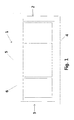
- Fig. 1 shows a schematic view of a dormer 1 according to the invention.
- the dormer 1 comprises two sides 2, 3, a bottom part 4 and a top part 5.
- the dormer's 1 roof is at its front side, as shown in the figure, surrounded by a fascia 6.
- the dormer 1 comprises three windows 7.
- Fig. 2 shows a schematic sectional side view of dormer 1 according to the invention.
- the dormer 1 is positioned on a sloping roof construction 8.
- a frame 9 is connected to the sloping roof construction 8.
- a top construction 10, as shown in Fig. 5 is positioned on said frame 9 and connected thereto.
- This provides a secure mutual coupling of frame 9 and top construction 10.
- the mutual coupling may for example be obtained through bolt and nut connections or screws.
- Frame 9 comprises at top part 11, as further shown in Fig. 4 , a weir 12 being positionable below an existing roof cladding 13.
- Rainwater, originating from roof cladding 13, schematically identified by arrow 15 in Fig. 3 will be drained through a gutter 14 provided in frame 9 (as shown in Fig. 2 ).
- Frame 9 may be connected to the roof construction 8 between the beams or on the beams.
- Fig. 4 shows frame 9, wherein a sidebeam 16 has been shown, provided at side 2, as well as a top beam 17 and a bottom beam 18.
- a left side beam is present as well, but is not shown in the figure.
- Beams 16, 17, 18 together with left side beam provide a continuous box construction that is connected to the sloping roof construction and that provides a connection platform for positioning the top construction 10.
- the top parts of the beams schematically identified by reference numerals 19, 20, 21 for beams 17, 18, 16 serve as bearing surface for top construction 10.
- said top construction 10 comprises support bases 22, 23, 24, as identified in Fig. 5 .
- beam 17 comprises a ridge 25.
- a gripping element 26 that has been provided at top construction 10, may grab when top construction 10 is lowered onto frame 9 in a position as shown in Fig. 6 .
- Said gripping element 26 grabs around ridge 25, serving as catch element 25, so as to yield a bead connection providing a pivotable connection between frame 9 and top construction 10.
- Said top construction 10 may subsequently be rotated around said bead connection in the direction of arrow 27 as shown in Fig. 6 .
- a recess 28 has been provided in a down most support base 23 of top construction 10 for receiving a ridge 29 that has been provided at an down most beam 18.
- Fig. 7 shows a detailed schematic side view of part of the dormer 1.
- the roof surface 30 slopes somewhat towards gutter 14 through which rain water is drained from roof surface 30 into gutter 14. It will then reach the regular roof cladding 13 provided at the sides 2, 3 of dormer 1 on the sloping roof construction 8, as shown in Fig. 8 .
- Fig. 8 further shows a side beam 16 of frame 9 and a side panel 32 of top construction 10, comprising a beam or plate shaped element 10 comprising a connection plate of nail strip 37 connected thereto.
- Said side panel 32 comprises a U-shaped recess 33 at the part supported by the beam 16, such that the legs of said U-shape are made up of the nail strip 37 and trim 37. Such provides protection against moisture and wind from penetrating.
- Part of the recess 33 not received by said side beam 16 provides for ventilation.
- a compressible material has been provided that yields an excellent seal.
- Nail strip 37 abuts side beam 16 of frame 9.
- a screw or nail connection may be provided at position 34 for mutually connecting frame 9 and top construction 10.
- a nail strip 36 is provided at side beam 16 of frame 9, abutting spar 35 being part of the sloping roof construction.
- Said nail strip 36 may be connected to spar 35 by means of a nail or screw connection.
- a combined connection of frame 9 to spar 35 and top construction 10 provides for a stable connection of said dormer to the sloping roof construction.
- the invention also embodies any combination of measures and features that have been described independently of each other.
Landscapes
- Engineering & Computer Science (AREA)
- Architecture (AREA)
- Physics & Mathematics (AREA)
- Electromagnetism (AREA)
- Civil Engineering (AREA)
- Structural Engineering (AREA)
- Tents Or Canopies (AREA)
- Roof Covering Using Slabs Or Stiff Sheets (AREA)
Applications Claiming Priority (2)
| Application Number | Priority Date | Filing Date | Title |
|---|---|---|---|
| NL1040172 | 2013-04-21 | ||
| NL2011324A NL2011324C2 (nl) | 2013-04-21 | 2013-08-20 | Dakkapel en werkwijze voor het plaatsen ervan. |
Publications (1)
| Publication Number | Publication Date |
|---|---|
| EP2792807A1 true EP2792807A1 (fr) | 2014-10-22 |
Family
ID=50513716
Family Applications (1)
| Application Number | Title | Priority Date | Filing Date |
|---|---|---|---|
| EP20140164858 Withdrawn EP2792807A1 (fr) | 2013-04-21 | 2014-04-16 | Lucarne et procédé de montage d'une telle lucarne |
Country Status (2)
| Country | Link |
|---|---|
| EP (1) | EP2792807A1 (fr) |
| NL (1) | NL2011324C2 (fr) |
Citations (4)
| Publication number | Priority date | Publication date | Assignee | Title |
|---|---|---|---|---|
| NL7304765A (fr) * | 1972-04-11 | 1973-10-15 | ||
| FR2570409A1 (fr) * | 1984-09-17 | 1986-03-21 | Eger Wilhelm | Fenetres tridimensionnelles pivotantes et coulissantes pour toitures en pente |
| DE8905436U1 (de) * | 1989-04-29 | 1990-06-21 | Dickgreber, Hans, Dipl.-Ing., 4780 Lippstadt | Dachgaube |
| NL8900270A (nl) * | 1989-02-03 | 1990-09-03 | Nijhuis Toelevering B V | Dakkapel en werkwijze voor de vervaardiging daarvan. |
-
2013
- 2013-08-20 NL NL2011324A patent/NL2011324C2/nl not_active IP Right Cessation
-
2014
- 2014-04-16 EP EP20140164858 patent/EP2792807A1/fr not_active Withdrawn
Patent Citations (4)
| Publication number | Priority date | Publication date | Assignee | Title |
|---|---|---|---|---|
| NL7304765A (fr) * | 1972-04-11 | 1973-10-15 | ||
| FR2570409A1 (fr) * | 1984-09-17 | 1986-03-21 | Eger Wilhelm | Fenetres tridimensionnelles pivotantes et coulissantes pour toitures en pente |
| NL8900270A (nl) * | 1989-02-03 | 1990-09-03 | Nijhuis Toelevering B V | Dakkapel en werkwijze voor de vervaardiging daarvan. |
| DE8905436U1 (de) * | 1989-04-29 | 1990-06-21 | Dickgreber, Hans, Dipl.-Ing., 4780 Lippstadt | Dachgaube |
Also Published As
| Publication number | Publication date |
|---|---|
| NL2011324C2 (nl) | 2014-10-23 |
Similar Documents
| Publication | Publication Date | Title |
|---|---|---|
| EP3406818B1 (fr) | Ensemble de lucarne | |
| JP2017533365A (ja) | 雨除け付き屋根トラスの組み立て方法および雨除け付き屋根トラス束 | |
| KR101476584B1 (ko) | 건물용 차양장치 설치구조 | |
| US20250075507A1 (en) | Draining member | |
| JP5827351B2 (ja) | 分割式屋根材 | |
| US12291874B2 (en) | Building and flashing | |
| JP5765725B2 (ja) | 換気棟及び下り棟用換気棟 | |
| CN205637363U (zh) | 用于坡屋顶有组织排水的檐构造及包含其的坡屋顶 | |
| CN209585739U (zh) | 一种预制舱装配式屋顶结构 | |
| NL2011324C2 (nl) | Dakkapel en werkwijze voor het plaatsen ervan. | |
| US20200181916A1 (en) | Roof vent for a corrugated metal roof | |
| CN208023848U (zh) | 一种金属屋面天窗防水节点结构 | |
| CN205476135U (zh) | 用于山墙处的遮蔽式檐口及含檐口构造的平屋顶 | |
| KR101897195B1 (ko) | 건물용 차양부재 | |
| AU2019204459B2 (en) | A Roof | |
| JP6047113B2 (ja) | 庇取付け構造および方法 | |
| FI129901B (en) | GUTTER, GUTTER STRUCTURE, WHICH INCLUDES A GUTTER, AND A PROCEDURE FOR ASSEMBLING A GUTTER STRUCTURE | |
| JP3583754B2 (ja) | 接合樋区分式棟部屋根構造 | |
| JP5921978B2 (ja) | 屋根構造 | |
| AU2007100612A4 (en) | An improved method for attaching pergolas etc to new and existing structures | |
| JP2004084220A (ja) | 組立構造物の屋根ユニット設置方法 | |
| JPH077442Y2 (ja) | ルーフバルコニー | |
| JPS5929052Y2 (ja) | 建築用板 | |
| NL2012070C2 (nl) | Geprefabriceerd dakelement met ten minste een zonnepaneel, bouwwerk en werkwijze. | |
| CN207110266U (zh) | 一种竹制屋顶 |
Legal Events
| Date | Code | Title | Description |
|---|---|---|---|
| PUAI | Public reference made under article 153(3) epc to a published international application that has entered the european phase |
Free format text: ORIGINAL CODE: 0009012 |
|
| 17P | Request for examination filed |
Effective date: 20140416 |
|
| AK | Designated contracting states |
Kind code of ref document: A1 Designated state(s): AL AT BE BG CH CY CZ DE DK EE ES FI FR GB GR HR HU IE IS IT LI LT LU LV MC MK MT NL NO PL PT RO RS SE SI SK SM TR |
|
| AX | Request for extension of the european patent |
Extension state: BA ME |
|
| R17P | Request for examination filed (corrected) |
Effective date: 20150420 |
|
| RBV | Designated contracting states (corrected) |
Designated state(s): AL AT BE BG CH CY CZ DE DK EE ES FI FR GB GR HR HU IE IS IT LI LT LU LV MC MK MT NL NO PL PT RO RS SE SI SK SM TR |
|
| 17Q | First examination report despatched |
Effective date: 20151102 |
|
| GRAP | Despatch of communication of intention to grant a patent |
Free format text: ORIGINAL CODE: EPIDOSNIGR1 |
|
| INTG | Intention to grant announced |
Effective date: 20160613 |
|
| STAA | Information on the status of an ep patent application or granted ep patent |
Free format text: STATUS: GRANT OF PATENT IS INTENDED |
|
| STAA | Information on the status of an ep patent application or granted ep patent |
Free format text: STATUS: THE APPLICATION IS DEEMED TO BE WITHDRAWN |
|
| 18D | Application deemed to be withdrawn |
Effective date: 20161025 |