EP2792918A1 - Stellgerät für eine verfahrenstechnische Anlage - Google Patents
Stellgerät für eine verfahrenstechnische Anlage Download PDFInfo
- Publication number
- EP2792918A1 EP2792918A1 EP14001243.6A EP14001243A EP2792918A1 EP 2792918 A1 EP2792918 A1 EP 2792918A1 EP 14001243 A EP14001243 A EP 14001243A EP 2792918 A1 EP2792918 A1 EP 2792918A1
- Authority
- EP
- European Patent Office
- Prior art keywords
- valve housing
- actuator
- deformation
- valve
- engagement
- Prior art date
- Legal status (The legal status is an assumption and is not a legal conclusion. Google has not performed a legal analysis and makes no representation as to the accuracy of the status listed.)
- Granted
Links
Images

Classifications
-
- F—MECHANICAL ENGINEERING; LIGHTING; HEATING; WEAPONS; BLASTING
- F16—ENGINEERING ELEMENTS AND UNITS; GENERAL MEASURES FOR PRODUCING AND MAINTAINING EFFECTIVE FUNCTIONING OF MACHINES OR INSTALLATIONS; THERMAL INSULATION IN GENERAL
- F16K—VALVES; TAPS; COCKS; ACTUATING-FLOATS; DEVICES FOR VENTING OR AERATING
- F16K27/00—Construction of housing; Use of materials therefor
- F16K27/02—Construction of housing; Use of materials therefor of lift valves
- F16K27/0254—Construction of housing; Use of materials therefor of lift valves with conical shaped valve members
-
- F—MECHANICAL ENGINEERING; LIGHTING; HEATING; WEAPONS; BLASTING
- F16—ENGINEERING ELEMENTS AND UNITS; GENERAL MEASURES FOR PRODUCING AND MAINTAINING EFFECTIVE FUNCTIONING OF MACHINES OR INSTALLATIONS; THERMAL INSULATION IN GENERAL
- F16K—VALVES; TAPS; COCKS; ACTUATING-FLOATS; DEVICES FOR VENTING OR AERATING
- F16K31/00—Actuating devices; Operating means; Releasing devices
- F16K31/12—Actuating devices; Operating means; Releasing devices actuated by fluid
- F16K31/126—Actuating devices; Operating means; Releasing devices actuated by fluid the fluid acting on a diaphragm, bellows, or the like
-
- F—MECHANICAL ENGINEERING; LIGHTING; HEATING; WEAPONS; BLASTING
- F16—ENGINEERING ELEMENTS AND UNITS; GENERAL MEASURES FOR PRODUCING AND MAINTAINING EFFECTIVE FUNCTIONING OF MACHINES OR INSTALLATIONS; THERMAL INSULATION IN GENERAL
- F16K—VALVES; TAPS; COCKS; ACTUATING-FLOATS; DEVICES FOR VENTING OR AERATING
- F16K27/00—Construction of housing; Use of materials therefor
- F16K27/02—Construction of housing; Use of materials therefor of lift valves
- F16K27/0281—Housings in two parts which can be orientated in different positions
-
- F—MECHANICAL ENGINEERING; LIGHTING; HEATING; WEAPONS; BLASTING
- F16—ENGINEERING ELEMENTS AND UNITS; GENERAL MEASURES FOR PRODUCING AND MAINTAINING EFFECTIVE FUNCTIONING OF MACHINES OR INSTALLATIONS; THERMAL INSULATION IN GENERAL
- F16B—DEVICES FOR FASTENING OR SECURING CONSTRUCTIONAL ELEMENTS OR MACHINE PARTS TOGETHER, e.g. NAILS, BOLTS, CIRCLIPS, CLAMPS, CLIPS OR WEDGES; JOINTS OR JOINTING
- F16B2200/00—Constructional details of connections not covered for in other groups of this subclass
- F16B2200/99—Fasteners with means for avoiding incorrect assembly or positioning
-
- F—MECHANICAL ENGINEERING; LIGHTING; HEATING; WEAPONS; BLASTING
- F16—ENGINEERING ELEMENTS AND UNITS; GENERAL MEASURES FOR PRODUCING AND MAINTAINING EFFECTIVE FUNCTIONING OF MACHINES OR INSTALLATIONS; THERMAL INSULATION IN GENERAL
- F16B—DEVICES FOR FASTENING OR SECURING CONSTRUCTIONAL ELEMENTS OR MACHINE PARTS TOGETHER, e.g. NAILS, BOLTS, CIRCLIPS, CLAMPS, CLIPS OR WEDGES; JOINTS OR JOINTING
- F16B39/00—Locking of screws, bolts or nuts
- F16B39/02—Locking of screws, bolts or nuts in which the locking takes place after screwing down
- F16B39/10—Locking of screws, bolts or nuts in which the locking takes place after screwing down by a plate, spring, wire or ring immovable with regard to the bolt or object and mainly perpendicular to the axis of the bolt
- F16B39/108—Locking of screws, bolts or nuts in which the locking takes place after screwing down by a plate, spring, wire or ring immovable with regard to the bolt or object and mainly perpendicular to the axis of the bolt with a locking washer under the nut or bolt head having at least one tongue or lug folded against the nut or bolt head, or against the object itself
-
- F—MECHANICAL ENGINEERING; LIGHTING; HEATING; WEAPONS; BLASTING
- F16—ENGINEERING ELEMENTS AND UNITS; GENERAL MEASURES FOR PRODUCING AND MAINTAINING EFFECTIVE FUNCTIONING OF MACHINES OR INSTALLATIONS; THERMAL INSULATION IN GENERAL
- F16K—VALVES; TAPS; COCKS; ACTUATING-FLOATS; DEVICES FOR VENTING OR AERATING
- F16K27/00—Construction of housing; Use of materials therefor
Definitions
- the invention relates to a control device or a valve arrangement for a process plant, such as a petrochemical plant, a brewery, a nuclear facility or the like.
- the actuator includes a control valve, with a valve housing, a valve seat and a valve member, and a top, such as a yoke, a lantern or a drive rod or drive shaft guide.
- the top is adapted to be screwed into a passage opening in the valve housing to serve as a supporting structure for connecting an actuator housing.
- the actuator does not necessarily have to be equipped with an actuator attached to the bonnet, such as a pneumatic actuator.
- the actuator can also be retrofitted. Usually, however, the actuator is a unit of control valve, upper part and actuator.
- An example of a positioning device is off US 6,905,108 B2 in which the upper part realizes both a yoke function and a drive-rod guiding function in a support structure made in one piece.
- a seal assembly such as a seal pack, is housed in an actuating rod passageway of the top to seal the control valve interior in the area of the actuator rod or actuator drive shaft passageway.
- a proven actuator is off DE 10 2010 025 635 B4 known, in which the upper part receives the seal package and compression springs for the axial bias of the packing.
- the upper part is screwed to the passage opening of the valve housing.
- the top serves to guide the actuating rod of the actuator for actuating the valve member with respect to the valve seat.
- an actuating device or a valve arrangement for a process plant, such as a petrochemical plant, a brewery, a nuclear facility or the like, is provided.
- the actuating device comprises a control valve with a valve housing which can be connected to pipelines of the system and structurally defines a valve seat in the interior, with which an adjustable valve member of the control valve occlusive, sometimes even completely open, works together.
- the valve housing actuator side comprises a passage opening in particular for performing a actuated by the actuator control rod which carries the valve member at the valve seat side end.
- the actuator has an upper part, which can be referred to in the field of process field equipment as a yoke, lantern or drive rod or drive shaft guide.
- the top is made as a separate mounting part of the actuator to provide the ability to incorporate a large access opening for easy access opening in the valve housing.
- the upper part can be in one or more parts in order to realize the yoke, lantern or guide function.
- the upper part is designed to be screwed into the lead-through opening, the upper part serving at least partially as a coupling structure for supporting the actuator to the valve housing can.
- a deformation buffer is arranged or formed on opposing screw stop surfaces of the upper part and of the valve housing, which can be de-deformed in a predetermined manner during screwing, in particular when screwing in the upper part.
- the deformation buffer serves to avoid a sudden generation of axial ringpress adoptedn between the fferanschlags vom by the construction of axial Verschraubungspress principle is progressively delayed in the course of screwing. In this way, it is also possible for an inexperienced assembly personnel to produce a sufficient Montagefeststellkraft between the upper part and the valve housing, wherein a desired rotational position of the upper part relative to the valve housing can be taken accurately position.
- An advantage of the deformation buffer is, in particular, to dampen pressure surges occurring in the process medium such that the upper part does not loosen. This advantage results from the buffer compliance by means of elastic deformation of the deformation buffer.
- the fferably, the fferanschlags simulation of the valve housing is formed by a respect to an axial extension direction of an actuating rod or actuating shaft of the actuator radial end face of a protruding housing neck, while the screw stop surface of the upper part may be formed by a radially outer or radially inner annular shoulder, depending on the Whether the upper part is screwed into the passage opening of the valve housing or the annular shoulder radially surrounds the housing neck of the valve housing.
- the deformation buffer is formed as a separate base ring structure, which may have as a basic shape a disc shape, which can provide even with this basic shape a non-negligible deformation volume to achieve the desired Vercardverzögerung when building the Verschraubpresskraft.
- the deformation buffer may have a predetermined profile in the form of an annular disk, such as a wave structure, in order to increase the desired deformation volume.
- the deformation buffer can also be formed on the upper side or on the valve housing side from one piece with the upper part or with the valve housing.
- the deformation buffer is coupled to the upper part or the valve housing such that when the upper part is screwed, the deformation buffer is held stationary relative to the upper part or the valve housing.
- the deformation buffer can be equipped with an anti-rotation, the one Mitvermosen when screwing the upper part against either the upper part or the valve housing prevented.
- the deformation buffer is inserted as a separate mounting part between the upper part and the valve housing.
- the deformation buffer preferably has a valve housing facing in particular annular clamping side and the upper part facing particular annular clamping side.
- the deformation buffer is designed as a disk-shaped, in particular closed, base ring structure, the two clamping sides of which are preferably planar in sections.
- the deformation buffer may have at least one protruding engagement nose, in particular for forming the anti-twist device.
- the engagement nose preferably protrudes from one or both clamping sides of the base ring structure.
- the least one engaging lug can preferably engage loosely in a recess complementary to the shape on the screw stop surface of the upper part or of the valve housing.
- the at least one engagement nose can be designed as a solid body or a draft.
- the engagement recess can be designed as a blind hole.
- the at least one engagement nose can be fixed as a solid body by welding.
- a plurality of engagement lugs are formed in particular with a constant circumferential section of 120 °, 90 ° or 60 ° between adjacent engagement lugs on the base ring structure.
- all engagement lugs are formed on one of the two clamping sides of the base structure.
- the upper part or the valve housing may have the same number of engagement recesses or a larger number of engagement recesses with respect to the number of engagement lugs.
- the engagement recesses are arranged such that in a certain rotational position, the base ring structure is held stationary on the upper part or the valve housing, while all engagement lugs are received in engagement recesses.
- the deformation buffer has at least one predetermined deformation zone on a clamping side facing the upper part and / or the valve housing, in particular the respective screw stop surfaces.
- the target deformation zone is a opposite the particular flat clamping side localized area and includes a predetermined deformation volume.
- the at least one desired deformation zone is preferably formed only on one of the two clamping sides, while the other clamping side is designed without deformation zones. The desired deformation zone comes when screwing the upper part into contact with the respective steranschlags Type and is gradually deformed during subsequent further screwing.
- the geometry of the deformation zone can predeterminably set the structure of axial clamping forces between the upper part and the valve housing.
- the at least one desired deformation zone is realized by at least one localized raised dome projecting from one of the planar clamping sides of the base structure.
- the protrusion is formed by an impression of the disk-shaped base ring structure, so that the at least one desired deformation zone has the same cross-sectional thickness as the remaining part of the base ring structure. This is intended to ensure that, when the set deformation zone deforms, one of the protrusions is provided with corresponding concavity, wherein the material of the at least one set deformation zone can escape into the concave free space. In this way, a homogeneous surface pressing force transfer between the upper part, the deformation buffer and the valve housing can be achieved.
- a plurality of predetermined deformation zones are preferably formed with a constant circumferential distance of 120 °, 90 ° or 60 ° to the base structure.
- four or more deformation zones, in particular six deformation zones are arranged.
- both the at least one engagement lug of the anti-twist device and the at least one predetermined deformation zone project from the same flat clamping side of the base ring structure.
- the at least one engagement lug and the at least one predetermined deformation zone are opposite to a flat clamping side of the base ring structure.
- the engagement nose preferably faces the valve housing.
- the opposite, in particular the upper part facing the flat clamping side is provided with the concavity of the at least one predetermined deformation zone opposite concave embossing.
- the at least one engagement lug of the anti-twist device and the at least one predetermined deformation zone protrude from the same side of the base structure and preferably face the valve housing.
- the deformation buffer has a securing tab, which is arranged in particular on the outer circumference of the base ring structure.
- the locking tab is bent over to the upper part or the valve body after completing the screwing procedure.
- the bending direction of the securing tab should be opposite to the Vorstehraum the at least one engagement nose and / or the at least one target deformation zone.
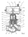
- FIG. 1 In general, a control device according to the invention is provided with the reference numeral 1.
- the actuator 1 comprises three main components, namely the control valve 3, a bolted to the control valve 3 upper part 5 and a rigidly coupled to the control valve 3 actuator, which is optionally grown for the realization of the actuator or can be added later.
- the actuator 7 is realized as a pneumatic drive and equipped with two pneumatic working chambers 11, 13 which are separated from each other by a membrane 15 airtight.
- a coupling ring 17 is attached, which allows a rigid coupling of the diaphragm 15 to a drive rod 21 of the actuator 7.
- the membrane 15 is clamped between two drive housing halves 23a, 23b, which limit the working chambers 11, 13, and in which pneumatic connections 25a, 25b are provided.
- a lower drive housing half 23 b has an output opening for passing through the two-part drive rod 21, which comprises an actuator-side drive rod part 31 and a valve-side output rod part 33. Both rod parts 31, 33 are frictionally and / or positively coupled to each other by a rod coupler 35, wherein the rod coupler 35 may be formed by two clamps screwed together. The clamps engage in a rod coupler near recess of the output rod portion 33 a.
- the control valve 3 has a valve housing 54 which defines an inlet 37 and a drain 41, wherein the inlet 37 is separated from the drain 41 via a valve seat passage 43.
- the valve seat passage 43 receives a valve seat ring 45, which cooperates with a valve member 47 closing and opening, so that a flow through the control valve 3 either approved, partially approved or can be locked.
- the valve member 47 is fixed to one end of the output rod member 33.
- the valve housing 54 is rigidly coupled to the housing of the actuator 7, with the aid of the upper part 5, which may be formed as a yoke, lantern and / or drive rod or drive shaft guide.
- the upper part 5 is realized as a one-piece component, which forms both a laterally accessible yoke structure 51 and a rod or waveguide insert 53.
- the upper part 5 is an upper through-opening 55, which is provided with an internal thread, the valve housing 54 is screwed, for which the rod or wave guide insert 53 of the upper part 5 has a corresponding external thread.
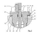
- the passage opening 55 is realized on the valve housing 54 by a neck 57, on the inner surface of which both the internal thread and the sealing surfaces are formed, wherein a leakage channel 61 extends radially through the vertical neck 57.
- the leakage channel 61 opens at an inner surface of the vertical neck 57 directly axially below the internal thread, wherein further below the sealing surfaces are formed, which cooperate with O-rings 63 of the rod or shaft guide insert 53.
- the rod or wave guide insert 53 has a sealed passage 65 for the implementation of the output rod portion 33.
- the passage 65 is extended in the form of a blind hole in the course towards the valve member 47, wherein in the blind hole-shaped extension an optionally axially biased seal package is arranged, which is connected by a plurality of sealing elements connected in series can be realized (see FIG. 2 ).
- the neck 57 has at its upper, the actuator 7 facing mounting side an annular, planar, radial screw abutment surface 71, which is perpendicular to the axial direction A, which corresponds to the translational adjustment direction of the control rod 21.
- the screw stop surface 71 has at a constant circumferential distance a plurality, preferably three receiving recesses 73, which may be formed, for example, as a blind hole. It is also possible for more than three such engagement recesses 73 to be formed on the screw stop surface 71.
- the screw abutment surface 71 cooperates with an opposite screw abutment counter surface 77 of a Montageradialabsatzes 75 of the upper part 5, which extends in the radial direction and the radial screw abutment counter surface 77 determines. Between the screw abutment counter surface 77 and the screw abutment surface 71 a forming a deformation buffer ring and disc-shaped base ring structure 81 is inserted. When screwing the upper part, the base ring structure 81 between the upper part 5 and the valve housing 54 is gradually deformed.
- the deformation buffer 81 has two basic functions, namely to achieve an anti-rotation lock and a predetermined setpoint position from upper part to valve part by means of a tolerated set deformation of the deformation buffer.
- the rotation ensures that the deformation buffer 81 is not rotated when screwing the upper part 5 in the valve housing 54 in the direction of rotation.
- the target deformation is realized by a plurality of target deformation zones formed by a part of the deformation buffer 81.
- the deformation zone is realized by a localized stamping, resulting in a convex curvature on one clamping side of the deformation buffer 81 and a concave impression on the other clamping side.
- the predetermined deformation zones are gradually deformed during the screwing of the upper part 5, that is to say when the deformation buffer 81 is braced. By means of this nominal deformation it is ensured that no excessive axial screwing forces possibly damaging the thread are applied and a sudden build-up of axial clamping forces is prevented.
- the inner diameter of the deformation buffer 81 substantially corresponds to the inner diameter of the passage 55.
- the outer diameter of the deformation buffer 81 substantially corresponds to the outer diameter of the radial shoulder 75.
- the ring width is substantially constant.
- the axial ring thickness is constant in the circumferential course.
- the deformation buffer 81 comprises on its annular surface (clamping side) 83 facing the valve housing 54 at least two, preferably three engagement lugs 85, all of which engage in the associated engagement recesses 73 in the screw abutment surface 71, thus when screwing and applying rotary Mit Meeting, the deformation buffer 81 whose circumferential position does not change.
- a corresponding engagement lug 85 can also be formed on the annular surface of the deformation buffer 81 facing the actuator 7, in which case the corresponding engagement depression on the screw stop counter surface 77 of the upper part 5 is to be formed.
- the deformation buffer 81 includes a plurality of indentations projecting convexly on an annular surface 83 and engaging with the screw abutment surface 71 or screw abutment counter surface 77.
- the protrusions 87 are plastically predetermined deformed to the Delay generation of clamping forces between the upper part 5 and the valve housing 54 with respect to the rotational path.
- the bulges 87 are concave on the annular surface side 89 of the base ring structure 81, while they are convex on the opposite annular surface 83.
- the engagement lugs 85 differ from the cambers 87 in that the axial strength of the engagement lug is greater than that of the camber 87, the camber 87 having a material thickness corresponding to the ring structure of the base ring structure 81, and the engagement lugs 85 the bulges 87 on the opposite side of the base ring structure 81 protrude.
- more than four such separate desired deformation zones in the form of bulges 87 at the same circumferential angular distances (about 60 °) are formed on the deformation buffer 81.
- the annular deformation buffer 81 has a final mounting tab 91 which is bent toward the top 5 or toward the valve housing 54, depending on the orientation of the engagement lobes and / or the buckling portions 87 of the desired deformation zone.
- the bending direction depends on which direction the engagement lugs 85 are directed. In FIG. 4 the engagement lugs 85 are directed toward the valve housing 54, so that the final mounting tab 91 is bent vertically upwards to the upper part 5.
Landscapes
- Engineering & Computer Science (AREA)
- General Engineering & Computer Science (AREA)
- Mechanical Engineering (AREA)
- Valve Housings (AREA)
Abstract
Description
- Die Erfindung betrifft ein Stellgerät oder eine Ventilanordnung für eine verfahrenstechnische Anlage, wie eine petrochemische Anlage, eine Brauerei, eine Nuklearanlage oder dergleichen.
- Das Stellgerät umfasst ein Stellventil, mit einem Ventilgehäuse, einem Ventilsitz und einem Ventilglied, und ein Oberteil, wie ein Joch, eine Laterne oder eine Antriebsstangen- oder Antriebswellenführung. Das Oberteil ist dazu ausgelegt, in eine Durchführungsöffnung im Ventilgehäuse eingeschraubt zu werden, um als tragende Struktur zur Anbindung eines Stellantriebsgehäuses zu dienen. Das Stellgerät muss nicht unbedingt mit einem an dem Oberteil befestigten Stellantrieb, wie einem pneumatischen Stellantrieb, ausgestattet sein. Der Stellantrieb kann auch nachträglich angebaut werden. Üblicherweise ist das Stellgerät allerdings eine Einheit aus Stellventil, Oberteil und Stellantrieb.
- Ein Beispiel für ein Stellgerät ist aus
US 6,905,108 B2 bekannt, bei dem das Oberteil sowohl eine Jochfunktion als auch eine Antriebsstangenführungsfunktion in einer einstückig hergestellten Tragstruktur realisiert. In einem Stellstangen-Durchführkanal des Oberteils ist eine Dichtungsanordnung, wie ein Dichtungspaket, untergebracht, um den Stellventilinnenraum im Bereich des Durchtrittkanals für die Stellantriebsstange oder der Stellantriebswelle des Stellantriebs abzudichten. - Ein bewährtes Stellgerät ist aus
DE 10 2010 025 635 B4 bekannt, bei dem das Oberteil das Dichtungspaket sowie Druckfedern zur axialen Vorspannung der Dichtungspackung aufnimmt. Das Oberteil ist an der Durchführöffnung des Ventilgehäuses eingeschraubt. Das Oberteil dient dazu, die Stellstange des Stellantriebs zum Betätigen des Ventilglieds gegenüber dem Ventilsitz zu führen. - Beim Einschrauben des Oberteils samt Joch zeigten sich Montageschwierigkeiten vor allem bei ungeübtem Bedienpersonal. Wegen der fehlenden Rotationssymmetrie des Oberteils ist es bei der an sich bewährten Verschraubung des Oberteils schwierig, eine bestimmte Relativposition des Oberteils gegenüber dem Ventilgehäuse bzw. dem Stellantriebsgehäuse einzustellen, ohne entweder das Oberteil gegenüber dem Ventilgehäuse zu überdrehen oder ihm eine zu geringe Schraubkraft zu verleihen. Aufgrund der recht hohen Hebelarme der Jochstruktur gegenüber der Schraubachse kann es auch dazu kommen, dass ein unabsichtliches Lösen des Oberteils von dem Ventilgehäuse verursacht wird, vor allem dann, wenn bei Erreichen der gewünschten Drehposition des Oberteils noch zu geringe Schraubkräfte zwischen dem Oberteil und dem Ventilgehäuse wirken.
- Es ist Aufgabe der Erfindung, die Nachteile des Stands der Technik zu überwinden, insbesondere ein Stellgerät für eine verfahrenstechnische Anlage dahingehend zu verbessern, dass sowohl die Gefahr eines unabsichtlichen Lösens des Oberteils von dem Ventilgehäuse minimiert wird als auch die Positionierung des Oberteils relativ zum Ventilgehäuse präzise und beliebig unter Beibehaltung einer festen und lösbaren Kopplung des Oberteils an das Ventilgehäuse sichergestellt ist.
- Diese Aufgabe wird durch die Merkmale von Anspruch 1 gelöst.
- Danach ist ein Stellgerät oder eine Ventilanordnung, insbesondere eine Stellventilanordnung, für eine verfahrenstechnische Anlage, wie eine petrochemische Anlage, eine Brauerei, eine Nuklearanlage oder dergleichen, vorgesehen. Das Stellgerät umfasst ein Stellventil mit einem Ventilgehäuse, das an Rohrleitungen der Anlage anschließbar ist und im Inneren einen Ventilsitz strukturell festlegt, mit dem ein stellbares Ventilglied des Stellventils verschließend, teilweise sogar vollständig öffnend, zusammenarbeitet. Zur Betätigung des Ventilglieds mittels eines Stellantriebs, der Teil des Stellgeräts sein kann, umfasst das Ventilgehäuse stellantriebsseitig eine Durchführöffnung insbesondere zum Durchführen einer durch den Stellantrieb betätigten Stellstange, die an deren ventilsitzseitigem Ende das Ventilglied trägt. Des Weiteren hat das Stellgerät ein Oberteil, das auf dem Gebiet der verfahrenstechnischen Feldgeräte als Joch, Laterne oder Antriebsstangen- oder Antriebswellenführung bezeichnet werden kann. Das Oberteil wird als separates Montageteil des Stellgeräts gefertigt, um die Möglichkeit bereitzustellen, eine für eine einfache Zugänglichkeit größere Durchführöffnung in dem Ventilgehäuse einzuarbeiten. Das Oberteil kann einteilig oder mehrteilig sein, um die Joch-, Laternen- oder Führungsfunktion zu realisieren. Das Oberteil ist dazu ausgelegt, in die Durchführöffnung eingeschraubt zu werden, wobei das Oberteil zumindest teilweise als Kopplungsstruktur zum tragenden Anbinden des Stellantriebs an das Ventilgehäuse dienen kann. Erfindungsgemäß ist an sich gegenüberliegenden Schraubanschlagsflächen des Oberteils und des Ventilgehäuses ein Deformationspuffer angeordnet oder ausgebildet, der beim Verschrauben, insbesondere beim Einschrauben, des Oberteils auf vorbestimmte Weise de-formierbar ist. Der Deformationspuffer dient dazu, ein schlagartiges Erzeugen von axialen Schraubpresskräften zwischen den Schraubanschlagsflächen zu vermeiden, indem der Aufbau axialer Verschraubungspresskräfte bei fortschreitender Einschraubbewegung drehwegverzögert wird. Auf diese Weise ist es auch für ein ungeübtes Montagepersonal möglich, eine ausreichende Montagefeststellkraft zwischen dem Oberteil und dem Ventilgehäuse zu erzeugen, wobei eine gewünschte Rotationsposition des Oberteils gegenüber dem Ventilgehäuse positionsgenau eingenommen werden kann. Ein Vorteil des Deformationspuffers besteht insbesondere darin, im Prozessmedium auftretende Druckschläge derart zu dämpfen, dass das Oberteil sich nicht lockert. Dieser Vorteil entsteht aus der Puffernachgiebigkeit mittels elastischer Verformung des Deformationspuffers.
- Vorzugweise ist die Schraubanschlagsfläche des Ventilgehäuses durch eine in Bezug auf eine axiale Erstreckungsrichtung einer Stellstange oder Stellwelle des Stellantriebs radiale Stirnfläche eines vorstehenden Gehäusehalses ausgebildet, während die Schraubanschlagsfläche des Oberteils durch einen radial außen liegenden oder radial innen liegenden Ringabsatz gebildet sein kann, je nach dem, ob das Oberteil in die Durchführöffnung des Ventilgehäuses eingeschraubt ist oder der Ringabsatz den Gehäusehals des Ventilgehäuses radial umgibt.
- Vorzugsweise ist der Deformationspuffer als separate Basisringstruktur ausgebildet, die als Grundgestalt eine Scheibenform aufweisen kann, welche selbst bei dieser Grundgestalt ein nicht vernachlässigbares Deformationsvolumen bereitstellen kann, um die gewünschte Verdrehverzögerung beim Aufbau der Verschraubpresskraft zu erreichen. Der Deformationspuffer kann in Form einer Ringscheibe eine vorbestimmte Profilierung aufweisen, wie eine Wellenstruktur, um das Soll-Deformations-Volumen zu vergrößern. Der Deformationspuffer kann auch oberteilseitig oder ventilgehäuseseitig aus einem Stück mit dem Oberteil bzw. mit dem Ventilgehäuse ausgebildet sein.
- Bei einer bevorzugten Ausführung der Erfindung ist der Deformationspuffer derart mit dem Oberteil oder dem Ventilgehäuse gekoppelt, dass beim Verschrauben des Oberteils der Deformationspuffer gegenüber dem Oberteil oder dem Ventilgehäuse ortsfest gehalten wird. Damit kann der Deformationspuffer mit einer Verdrehsicherung ausgestattet sein, die ein Mitverdrehen beim Verschrauben des Oberteils entweder gegenüber dem Oberteil oder dem Ventilgehäuse verhindert. Bei einer bevorzugten Ausführung der Erfindung ist der Deformationspuffer ist als separates Montageteil zwischen dem Oberteil und dem Ventilgehäuse eingelegt. Der Deformationspuffer hat vorzugsweise eine dem Ventilgehäuse zugewandte insbesondere ringförmige Klemmseite und eine dem Oberteil zugewandte insbesondere ringförmige Klemmseite.
- Vorzugsweise ist der der Deformationspuffer als eine scheibenförmige insbesondere geschlossene Basisringstruktur ausgebildet, dessen beide Klemmseiten vorzugsweise abschnittsweise eben geformt sind.
- Bei einer bevorzugten Ausführung der Erfindung kann insbesondere zur Bildung der Verdrehsicherung der Deformationspuffer wenigstens eine vorstehende Eingriffsnase aufweisen. Vorzugsweise ragt die Eingriffsnase von einer oder beiden Klemmseiten der Basisringstruktur vor. Zur Bildung der Verdrehsicherung kann die wenigsten eine Eingriffsnase in einer dazu formkomplementären Eingriffsvertiefung an der Schraubanschlagsfläche des Oberteils oder des Ventilgehäuses vorzugsweise lose eingreifen. Die wenigstens eine Eingriffsnase kann als Vollkörper oder Durchzug ausgebildet sein. Die Eingriffsvertiefung kann als Sackloch ausgeführt sein. Bei einer Ausbildung der Erfindung kann die wenigstens eine Eingriffsnase als Vollkörper durch Aufschweißen befestigt sein.
- Vorzugsweise sind mehrere Eingriffsnasen insbesondere mit einem konstanten Umfangsabschnitt von 120°, 90° oder 60° zwischen benachbarten Eingriffsnasen an der Basisringstruktur ausgebildet. Vorzugsweise sind sämtliche Eingriffsnasen an einer der beiden Klemmseiten der Basisstruktur ausgebildet. An der Schraubanschlagsfläche des Oberteils oder des Ventilgehäuses können in Bezug auf die Anzahl der Eingriffsnasen gleich viele Eingriffsvertiefungen oder eine größere Anzahl von Eingriffsvertiefungen aufweisen. Dabei sind die Eingriffsvertiefungen derart angeordnet, dass in einer bestimmten Rotationsposition die Basisringstruktur ortsfest an dem Oberteil oder dem Ventilgehäuse gehalten wird, während sämtliche Eingriffsnasen in Eingriffsvertiefungen aufgenommen sind.
- Bei einer Weiterbildung der Erfindung hat der Deformationspuffer auf einer dem Oberteil und/oder dem Ventilgehäuse insbesondere den jeweiligen Schraubanschlagsflächen zugewandten Klemmseite wenigstens eine Solldeformationszone. Die Solldeformationszone ist ein gegenüber der insbesondere ebenen Klemmseite örtlich begrenzter Bereich und umfasst ein vorbestimmtes Deformationsvolumen. Die wenigstens eine Soll-Deformationszone ist vorzugsweise nur auf einer der beiden Klemmseiten ausgebildet, während die andere Klemmseite solldeformationszonenfrei ausgeführt ist. Die Solldeformationszone kommt beim Verschrauben des Oberteils in einen Kontakt mit der jeweiligen Schraubanschlagsfläche und wird beim anschließenden Weiterschrauben allmählich deformiert.
- Bei einer bevorzugten Ausführung der Erfindung kann die Geometrie der Deformationszone vorbestimmbar den Aufbau von axialen Klemmkräften zwischen dem Oberteil und dem Ventilgehäuse einstellen. Je höher die Anzahl der Deformationszonen, desto höhere Deformationskräfte sind erzeugbar; d.h. desto höhere axiale Verschraubklemmkräfte können je nach Verdrehweg des Oberteils realisiert werden.
- Bei einer bevorzugten Ausführung der Erfindung ist die wenigstens eine Solldeformationszone durch wenigstens eine örtlich begrenzte erhabene Wölbung realisiert, die von einer der ebenen Klemmseiten der Basisstruktur vorsteht. Vorzugsweise ist die Vorwölbung durch eine Einprägung der scheibenförmigen Basisringstruktur gebildet, so dass die wenigstens eine Soll-Deformationszone dieselbe Querschnittsstärke wie der restliche Teil der Basisringstruktur aufweist. Damit soll erreicht werden, dass beim Deformieren der Solldeformationszone eine der Vorwölbung entsprechende Konkavität bereitsteht, wobei in den konkaven Freiraum das Material der wenigstens einen Soll-Deformationszone ausweichen kann. Auf diese Weise ist ein homogener flächiger Presskraftübertrag zwischen dem Oberteil, dem Deformationspuffer und dem Ventilgehäuse erreichbar.
- Bei einer bevorzugten Ausführung der Erfindung sind mehrere Solldeformationszonen vorzugsweise mit einem konstante Umfangsabstand von 120°, 90° oder 60° an der Basisstruktur ausgebildet. Vorzugsweise sind vier oder mehr Deformationszonen, insbesondere sechs Deformationszonen angeordnet.
- Bei einer Weiterbildung der Erfindung stehen sowohl die wenigstens eine Eingriffsnase der Verdrehsicherung als auch die wenigstens eine Solldeformationszone von der gleichen ebenen Klemmseite der Basisringstruktur vor. Vorzugsweise stehen die wenigstens eine Eingriffsnase und die wenigstens eine Solldeformationszone entgegengesetzt von einer ebenen Klemmseite der Basisringstruktur vor. Dabei ist die Eingriffsnase vorzugsweise dem Ventilgehäuse zugewandt. Die gegenüber liegende, insbesondere dem Oberteil zugewandte ebene Klemmseite ist mit dem der Wölbung der wenigstens einen Solldeformationszone gegenüberliegenden konkaven Einprägung versehen. In einer vorteilhaften Ausgestaltung stehen die wenigstens eine Eingriffsnase der Verdrehsicherung und die wenigstens eine Solldeformationszone von der gleichen Seite der Basisstruktur vor und sind vorzugsweise dem Ventilgehäuse zugewandt.
- Bei einer bevorzugten Ausführung der Erfindung hat der Deformationspuffer eine Sicherungslasche, die insbesondere an dem Außenumfang der Basisringstruktur angeordnet ist. Die Sicherungslasche wird nach Abschluss des Verschraubvorgangs hin zum Oberteil oder zum Ventilgehäuse umgebogen. Vorzugsweise soll die Biegerichtung der Sicherungslasche entgegengesetzt der Vorstehrichtung der wenigstens einen Eingriffsnase und/oder der wenigstens einen Solldeformationszone gerichtet sein.
- Bevorzugte Ausgestaltungen sind in den Unteransprüchen angegeben.
- Weitere Eigenschaften, Vorteile und Merkmale der Erfindung werden durch die folgende Beschreibung von bevorzugten Ausführungen der Erfindung anhand der beiliegenden Zeichnungen deutlich, in denen zeigen:
- Figur 1
- eine Querschnittsansicht eines erfindungsgemäßen Stellgeräts mit einem Stellventil, einem Stellantrieb und einem das Stellventil mit dem Stellantrieb starr koppelnden Oberteil;
- Figur 2
- eine Querschnittsdetailansicht eines Übergangsbereichs des Feldgeräts nach
Figur 1 am Übergang zwischen dem Ventilgehäuse und dem eingeschraubten Oberteil; - Figur 3
- ein erfindungsgemäßer Deformationspuffer, der zwischen dem Ventilgehäuse und dem Oberteil zu verklemmen ist; und
- Figur 4
- eine Querschnittsansicht des Deformationspuffers entlang der Schnittlinie IV-IV gemäß
Figur 3 . - In
Figur 1 ist im Allgemeinen ein erfindungsgemäßes Stellgerät mit der Bezugsziffer 1 versehen. Das Stellgerät 1 umfasst drei Hauptbestandteile, nämlich das Stellventil 3, ein mit dem Stellventil 3 verschraubtes Oberteil 5 und einen mit dem Stellventil 3 starr gekoppelten Stellantrieb, der optional zur Realisierung des Stellgeräts angebaut ist oder nachträglich angebaut werden kann. - Der Stellantrieb 7 ist als pneumatischer Antrieb realisiert und mit zwei pneumatischen Arbeitskammern 11, 13 ausgestattet, die durch eine Membran 15 voneinander luftdicht getrennt sind. An der Membran 15 ist ein Kopplungsring 17 befestigt, der eine starre Ankopplung der Membran 15 an eine Antriebsstange 21 des Stellantriebs 7 zulässt. Die Membran 15 ist zwischen zwei Antriebsgehäusehälften 23a, 23b einklemmt, die die Arbeitskammern 11, 13 begrenzen, und in denen pneumatische Anschlüsse 25a, 25b vorgesehen sind.
- Eine untere Antriebsgehäusehälfte 23b umfasst eine Abtriebsöffnung zum Durchführen der zweigeteilten Antriebsstange 21, welche einen stellantriebsseitigen Antriebsstangenteil 31 und ein ventilseitigen Abtriebsstangenteil 33 umfasst. Beide Stangenteile 31, 33 sind durch einen Stangenkoppler 35 kraftschlüssig und/oder formschlüssig aneinander gekoppelt, wobei der Stangenkoppler 35 durch zwei miteinander verschraubte Schellen ausgebildet sein kann. Die Schellen greifen in eine stangenkopplersnahe Vertiefung des Abtriebsstangenteils 33 ein.
- Das Stellventil 3 hat ein Ventilgehäuse 54, das einen Zulauf 37 sowie einen Ablauf 41 festlegt, wobei der Zulauf 37 von dem Ablauf 41 über einen Ventilsitzdurchgang 43 getrennt ist. Der Ventilsitzdurchgang 43 nimmt einen Ventilsitzring 45 auf, der mit einem Ventilglied 47 verschließend und öffnend zusammenwirkt, so dass ein Durchfluss durch das Stellventil 3 entweder zugelassen, teilweise zugelassen oder gesperrt werden kann. Das Ventilglied 47 ist an einem Ende des Abtriebsstangenteils 33 befestigt.
- Das Ventilgehäuse 54 ist mit dem Gehäuse des Stellantriebs 7 starr gekoppelt, und zwar mit Hilfe des Oberteils 5, das als Joch, Laterne und/oder Antriebsstangen- oder Antriebswellenführung ausgebildet sein kann. In der in
Figur 1 dargestellten Ausführung ist das Oberteil 5 als einstückiges Bauteil realisiert, das sowohl eine seitlich zugängliche Jochstruktur 51 als auch einen Stangen- oder Wellenführungseinsatz 53 bildet. Das Oberteil 5 ist einer oberen Durchführöffnung 55, die mit einem Innengewinde versehen ist, des Ventilgehäuses 54 eingeschraubt, wobei dafür der Stangen- oder Wellenführungseinsatz 53 des Oberteils 5 ein entsprechendes Außengewinde hat. - Die Durchführöffnung 55 wird an dem Ventilgehäuse 54 durch einen Hals 57 realisiert, an deren Innenfläche sowohl das Innengewinde als auch Dichtflächen ausgebildet sind, wobei sich radial durch den Vertikalhals 57 hindurch ein Leckagekanal 61 erstreckt. Der Leckagekanal 61 mündet an einer Innenfläche des Vertikalhalses 57 unmittelbar axial unterhalb des Innengewindes, wobei weiter darunter die Dichtflächen ausgebildet sind, die mit O-Ringen 63 des Stangen- oder Wellenführungseinsatzes 53 zusammenwirken.
- Der Stangen- oder Wellenführungseinsatz 53 hat einen gedichteten Durchgang 65 zur Durchführung des Abtriebsstangenteils 33. Der Durchgang 65 ist im Verlauf hin zum Ventilglied 47 sacklochförmig erweitert, wobei in der sacklochförmigen Erweiterung ein gegebenenfalls axial vorgespanntes Dichtungspaket angeordnet ist, das durch mehrere in Reihe geschaltete Dichtungselemente realisiert sein kann (siehe
Figur 2 ). - Der Hals 57 hat an seiner oberen, dem Stellantrieb 7 zugewandten Montageseite eine ringförmige, ebene, radiale Schraubenanschlagsfläche 71, die bezüglich der Axialrichtung A, die der translatorischen Stellrichtung der Stellstange 21 entspricht, senkrecht verläuft. Die Schraubenanschlagsfläche 71 hat in einem konstanten Umfangsabstand mehrere, vorzugsweise drei Aufnahmevertiefungen 73, die beispielsweise als Sacklochbohrung ausgebildet sein können. Es können auch mehr als drei solche Eingriffsvertiefungen 73 an der Schraubenanschlagsfläche 71 ausgebildet sein. Die Schraubenanschlagsfläche 71 arbeitet mit einer gegenüber liegenden Schraubenanschlagsgegenfläche 77 eines Montageradialabsatzes 75 des Oberteils 5 zusammen, der sich in Radialrichtung erstreckt und die radiale Schraubenanschlagsgegenfläche 77 festlegt. Zwischen der Schraubenanschlagsgegenfläche 77 und der Schraubenanschlagsfläche 71 ist eine einen Deformationspuffer bildende ring- und scheibenförmige Basisringstruktur 81 eingelegt. Bei Verschrauben des Oberteils wird die Basisringstruktur 81 zwischen dem Oberteil 5 und dem Ventilgehäuse 54 allmählich deformiert. Der Deformationspuffer 81 hat zwei Grundfunktionen, nämlich eine Verdrehsicherung sowie eine vorbestimmte Sollposition von Oberteil zu Ventilteil mittels einer tolerierten Solldeformation des Deformationspuffers zu erreichen.
- Die Verdrehsicherung stellt sicher, dass der Deformationspuffer 81 beim Einschrauben des Oberteils 5 in das Ventilgehäuse 54 nicht in Drehrichtung mit gedreht wird. Die Solldeformation wird durch mehrere Solldeformationszonen realisiert, die durch einen Teil des Deformationspuffers 81 gebildet sind. Die Deformationszone wird durch eine örtlich begrenzte Prägung realisiert, wodurch sich auf einer Klemmseite des Deformationspuffers 81 eine konvexe Wölbung und auf der anderen Klemmseite eine konkave Einprägung ergibt. Die Solldeformationszonen werden während des Verschraubens des Oberteils 5, also beim Verspannen des Deformationspuffers 81 vorbestimmt allmählich deformiert. Mittels dieser Sollverformung wird sichergestellt, dass keine übermäßigen das Gewinde möglicherweise beschädigenden axialen Schraubkräfte aufgebracht werden und ein schlagartiger Aufbau axialer Klemmkräfte verhindert wird.
- Der Innendurchmesser des Deformationspuffers 81 entspricht im Wesentlichen dem Innendurchmesser des Durchgangs 55. Der Außendurchmesser des Deformationspuffers 81 entspricht im Wesentlichen dem Außendurchmesser des Radialabsatzes 75. Im Umfangsverlauf ist die Ringbreite im Wesentlichen konstant. Auch die axiale Ringstärke ist im Umfangsverlauf gleichbleibend.
- Zur Realisierung der Funktion der Verdrehsicherung umfasst der Deformationspuffer 81 auf seiner dem Ventilgehäuse 54 zugewandten Ringfläche (Klemmseite) 83 wenigstens zwei, vorzugsweise drei Eingriffsnasen 85, von denen alle in die zugeordneten Eingriffsvertiefungen 73 in der Schraubenanschlagsfläche 71 eingreifen, damit beim Verschrauben und Aufbringen von rotativen Mitnehmerkräften der Deformationspuffer 81 deren Umfangsposition nicht verändert.
- Es sei klar, dass eine entsprechende Eingriffsnase 85 auch an der dem Stellantrieb 7 zugewandten Ringfläche des Deformationspuffers 81 ausgebildet sein kann, wobei in diesem Fall die entsprechende Eingriffsvertiefung an der Schraubenanschlagsgegenfläche 77 des Oberteils 5 auszubilden ist.
- Um die Solldeformationszone bereitzustellen, umfasst der Deformationspuffer 81 mehrere Einprägungen, die an einer Ringfläche 83 konvex vorstehen und mit der Schraubenanschlagsfläche 71 oder Schraubenanschlagsgegenfläche 77 in Eingriff kommen. Beim Verpressen des Deformationspuffers werden die Vorwölbungen 87 plastisch vorbestimmt deformiert, um das Erzeugung von Klemmkräften zwischen dem Oberteil 5 und dem Ventilgehäuse 54 in Bezug auf den Drehweg zu verzögern.
- Die Wölbungen 87 sind auf der Ringflächenseite 89 der Basisringstruktur 81 konkav, während sie an der gegenüber liegenden Ringfläche 83 konvex sind. Somit unterscheiden sich die Eingriffsnasen 85 von den Wölbungen 87 dadurch, dass sich die axiale Stärke der Eingriffsnase größer als die der Wölbung 87 darstellt, wobei die Wölbung 87 eine Materialstärke aufweist, die der der Ringstruktur der Basisringstruktur 81 entspricht, und dass die Eingriffsnasen 85 bezüglich der Wölbungen 87 auf der gegenüberliegenden Seite der Basisringstruktur 81 hervorstehen.
- Vorzugsweise sind mehr als vier derartige separate Solldeformationszonen in Form von Wölbungen 87 bei gleichen Umfangswinkelabständen (etwa 60°) an dem Deformationspuffer 81 ausgebildet.
- Der ringförmige Deformationspuffer 81 hat eine Endmontagelasche 91, welche je nach Orientierung der Eingriffsnasen und/oder der Wölbungen 87 der Solldeformationszone hin zu dem Oberteil 5 oder hin zu dem Ventilgehäuse 54 gebogen wird. Die Biegerichtung hängt davon ab, in welche Richtung die Eingriffsnasen 85 gerichtet sind. In
Figur 4 sind die Eingriffsnasen 85 hin zu dem Ventilgehäuse 54 gerichtet, so dass die Endmontagelasche 91 vertikal nach oben hin zum Oberteil 5 umgebogen ist. - Die in der vorstehenden Beschreibung, den Figuren und den Ansprüchen offenbarten Merkmale können sowohl einzeln als auch in beliebiger Kombination für die Realisierung der Erfindung in den verschiedenen Ausgestaltungen von Bedeutung sein.
-
- 1
- Stellgerät
- 3
- Stellventil
- 5
- Oberteil
- 7
- Stellantrieb
- 11, 13
- pneumatische Arbeitskammern
- 15
- Membran
- 17
- Kopplungsring
- 23a, 23b
- Antriebsgehäusehälften
- 25a, 25b
- pneumatische Anschlüsse
- 31
- stellantriebsseitiges Antriebsstangenteil
- 33
- ventilseitiges Abtriebsstangenteil
- 35
- Stangenkoppler
- 37
- Zulauf
- 41
- Ablauf
- 43
- Ventilsitzdurchgang
- 45
- Ventilsitzring
- 47
- Ventilglied
- 51
- Jochstruktur
- 53
- Stangen- oder Wellenführungseinsatz
- 54
- Ventilgehäuse
- 55
- Durchführöffnung
- 57
- Hals
- 61
- Leckagekanal
- 63
- O-Ringe
- 65
- Durchgang
- 71
- Schraubenanschlagsfläche
- 73
- Eingriffsvertiefungen
- 75
- Montageradialabsatz
- 77
- Schraubenanschlagsgegenfläche
- 81
- Basisringstruktur/Deformationspuffer
- 83
- Ringfläche
- 85
- Eingriffsnase
- 87
- Vorwölbungen
- 89
- Ringflächenseite
- 91
- Endmontagelasche
- A
- Axialrichtung
Claims (10)
- Stellgerät (1) für eine verfahrenstechnische Anlage, wie eine petrochemische Anlage, eine Brauerei, eine Nuklearanlage oder dergleichen, umfassend ein Stellventil (3) mit einem Ventilgehäuse (54), einem Ventilsitz und einem Ventilglied (47), das über eine Durchführöffnung (55) in dem Ventilgehäuse (54) betätigbar ist, und ein Oberteil (5), wie ein Joch, eine Laterne oder eine Antriebsstangen- oder Antriebswellenführung, zum Verschrauben an der Durchführöffnung (55) und zum starren Koppeln des Ventilgehäuses (54) an einen Stellantrieb, dadurch gekennzeichnet, dass an sich gegenüberliegenden Schraubanschlagsflächen (71) des Oberteils (5) und des Ventilgehäuses (54) ein Deformationspuffer (81) angeordnet oder ausgebildet ist, der beim Verschrauben des Oberteils (5) auf vorbestimmte Weise deformierbar ist.
- Stellgerät (1) nach Anspruch 1, dadurch gekennzeichnet, dass der Deformationspuffer (81) mit dem Oberteil (5) oder dem Ventilgehäuse (54) derart gekoppelt ist, dass beim Verschrauben des Oberteils (5) der Deformationspuffer (81) gegenüber dem Oberteil (5) oder dem Ventilgehäuse (54) ortsfest gehalten wird.
- Stellgerät (1) nach Anspruch 1 oder 2, dadurch gekennzeichnet, dass der Deformationspuffer (81) eine scheibenförmige insbesondere geschlossene Basisringstruktur aufweist, insbesondere deren dem Oberteil (5) und dem Ventilgehäuse (54) zugewandten ringförmigen Klemmseiten abschnittweise eben geformt sind.
- Stellgerät (1) nach einem der vorstehenden Ansprüche, dadurch gekennzeichnet, dass der Deformationspuffer (81) wenigstens eine vorzugsweise von einer oder beiden Klemmseiten der Basisringstruktur vorstehenden Eingriffsnase (85) aufweist, die in einer insbesondere formkomplementären Eingriffsvertiefung (73) in einer Schraubanschlagsflächen (71) des Oberteils (5) oder des Ventilgehäuses (54) vorzugsweise lose eingreift, wobei insbesondere die wenigstens eine Eingriffsnase (85) als Vollkörper oder Durchzug ausgebildet ist und/oder die Eingriffsvertiefung (73) als Sackloch ausgebildet ist.
- Stellgerät (1) nach Anspruch 4, dadurch gekennzeichnet, dass mehrere Eingriffsnasen (85) vorzugsweise mit einem konstanten Umfangsabstand von 120°, 90° oder 60° an der Basisringstruktur (81) ausgebildet sind, wobei insbesondere bei gleicher oder größerer Anzahl von Eingriffsvertiefungen (73) sämtliche Eingriffsnase (85) darin aufgenommen sind.
- Stellgerät (1) nach einem der vorstehenden Ansprüche, dadurch gekennzeichnet, dass der Deformationspuffer (81) auf einer dem Oberteil (5) und/oder dem Ventilgehäuse (54) zugewandten Klemmseite wenigstens eine Solldeformationszone aufweist, die beim Verschrauben allmählich deformierbar ist.
- Stellgerät (1) nach Anspruch 6, dadurch gekennzeichnet, dass die wenigstens eine Solldeformationszone durch wenigstens eine Wölbung einer insbesondere scheibenförmigen Basisringstruktur (81) realisiert ist.
- Stellgerät (1) nach Anspruch 6 oder 7, dadurch gekennzeichnet, dass mehrere Solldeformationszonen vorzugsweise mit einem konstanten Umfangsabstand von 120°, 90° oder 60° an der Basisringstruktur (81) ausgebildet sind.
- Stellgerät (1) nach einem der vorstehenden Ansprüche 6 bis 8, dadurch gekennzeichnet, dass die wenigstens eine Eingriffsnase (85) der Verdrehsicherung vorzugsweise dem Ventilgehäuse (54) zugewandt ist und die wenigstens eine Solldeformationszone entgegengesetzt zur Eingriffsnase von der ebenen Klemmseite der Basisringstruktur (81) vorsteht.
- Stellgerät (1) nach einem der vorstehenden Ansprüche, dadurch gekennzeichnet, dass der Deformationspuffer (81) eine Sicherungslasche aufweist, die zum Abschluss der Verschraubung des Oberteils (5) hin zum Oberteil (5) oder zum Ventilgehäuse (54) umgebogen wird.
Applications Claiming Priority (1)
| Application Number | Priority Date | Filing Date | Title |
|---|---|---|---|
| DE102013006777.4A DE102013006777A1 (de) | 2013-04-18 | 2013-04-18 | Stellgerät für eine verfahrenstechnische Anlage |
Publications (2)
| Publication Number | Publication Date |
|---|---|
| EP2792918A1 true EP2792918A1 (de) | 2014-10-22 |
| EP2792918B1 EP2792918B1 (de) | 2016-10-26 |
Family
ID=50542762
Family Applications (1)
| Application Number | Title | Priority Date | Filing Date |
|---|---|---|---|
| EP14001243.6A Not-in-force EP2792918B1 (de) | 2013-04-18 | 2014-04-03 | Stellgerät für eine verfahrenstechnische Anlage |
Country Status (3)
| Country | Link |
|---|---|
| US (1) | US9528623B2 (de) |
| EP (1) | EP2792918B1 (de) |
| DE (1) | DE102013006777A1 (de) |
Cited By (1)
| Publication number | Priority date | Publication date | Assignee | Title |
|---|---|---|---|---|
| EP4134575A1 (de) * | 2021-08-11 | 2023-02-15 | Gemü Gebr. Müller Apparatebau GmbH & Co. Kommanditgesellschaft | Ventilantrieb, ventilanordnung und verfahren |
Families Citing this family (2)
| Publication number | Priority date | Publication date | Assignee | Title |
|---|---|---|---|---|
| DE202018105378U1 (de) * | 2018-09-19 | 2019-12-20 | Samson Aktiengesellschaft | Halter für einen Magnet, Stellarmaturpositionserfassungseinrichtung und Stellarmatur |
| EP4419819A4 (de) | 2021-10-20 | 2025-08-27 | Clementina Clemco Holdings Inc | Dosierventil für abrasive medien |
Citations (10)
| Publication number | Priority date | Publication date | Assignee | Title |
|---|---|---|---|---|
| GB540325A (en) * | 1941-02-10 | 1941-10-14 | John Banks Dunlop | Nut-lock |
| US2456493A (en) * | 1947-02-26 | 1948-12-14 | Phillips B Drane | Time controlled valve |
| US3204925A (en) * | 1962-05-15 | 1965-09-07 | Montuori Enrico | Valve with nonrotating valve stem |
| US4452428A (en) * | 1981-12-24 | 1984-06-05 | Scaramucci John P | Bonnet locking system for a valve |
| GB2138912A (en) * | 1983-04-26 | 1984-10-31 | British Nuclear Fuels Ltd | Locking tab washer |
| US4943033A (en) * | 1988-09-20 | 1990-07-24 | Pacson Limited | Flow control valve |
| FR2712645A1 (fr) * | 1993-11-18 | 1995-05-24 | Vanatome | Rondelle pour le freinage d'un assemblage vis-écrou. |
| US6905108B2 (en) | 2001-11-15 | 2005-06-14 | Fisher Controls International Llc. | Control valve flow adjustment device |
| DE102005060120A1 (de) * | 2005-12-16 | 2007-06-21 | Danfoss A/S | Heizkörper-Einbauventil |
| DE102010025635B4 (de) | 2010-06-30 | 2012-05-31 | Samson Ag | Stellgerät |
Family Cites Families (20)
| Publication number | Priority date | Publication date | Assignee | Title |
|---|---|---|---|---|
| US2307440A (en) * | 1940-11-07 | 1943-01-05 | Wylie G Wilson | Sealing ring |
| US2316974A (en) * | 1941-12-02 | 1943-04-20 | Dresser Mfg Company | Saddle gasket |
| US2449119A (en) * | 1944-10-14 | 1948-09-14 | John R Holicer | Control fitting for liquefied petroleum gas tanks |
| US2657078A (en) * | 1949-08-19 | 1953-10-27 | John R Virgil | Gasket seal for pipe joints |
| US3175573A (en) * | 1962-06-04 | 1965-03-30 | Manning Maxwell & Moore Inc | Packing-adjusting means for capped valve |
| US3257095A (en) * | 1962-12-12 | 1966-06-21 | Chester A Siver | Valve construction particularly packed or sealed |
| US3463196A (en) * | 1967-09-08 | 1969-08-26 | Ernest T Richardson | Flange protector |
| US3721452A (en) * | 1971-02-22 | 1973-03-20 | Psi Prod Inc | Gasket assembly for pipe flanges |
| US3993284A (en) * | 1975-06-26 | 1976-11-23 | Acf Industries, Incorporated | Connection of actuator cylinder housing to valve bonnet |
| IT7653664U1 (it) * | 1976-11-25 | 1978-05-25 | Fiat Spa | Guarnizione di tenuta per motori a combustione interna, incorporante perni di centraggio |
| US4436310A (en) * | 1981-09-18 | 1984-03-13 | Toyota Jidosha Kogyo Kabushiki Kaisha | Sealing device for joint |
| US4421293A (en) * | 1981-09-28 | 1983-12-20 | Whitey Co. | End cap assembly |
| US4522536A (en) * | 1983-08-08 | 1985-06-11 | Vidrine Sharon J | Apparatus for and method of fluid sealing channeled flange connectors of under-water pipe line sections |
| DE3610541A1 (de) * | 1986-03-27 | 1987-10-01 | Lechler Elring Dichtungswerke | Zylinderkopfdichtung |
| US5145219A (en) * | 1990-08-01 | 1992-09-08 | Cajon Company | Tube coupling with gasket retainer |
| JPH0826101A (ja) * | 1994-07-13 | 1996-01-30 | Sumitomo Electric Ind Ltd | ブレーキ液圧制御装置 |
| FR2775328B1 (fr) * | 1998-02-26 | 2000-04-28 | Christian Loth | Joint d'etancheite pour bride de tuyauterie |
| US7364166B2 (en) * | 2003-01-24 | 2008-04-29 | Applied Engineered Surfaces, Inc. | Seal and retainer for a fluid connection |
| US20050280214A1 (en) * | 2004-06-22 | 2005-12-22 | Richards Jeffrey L | Elastomer coated screen gasket |
| ITMI20060037U1 (it) * | 2006-02-01 | 2007-08-02 | Caleffi Spa | Valvola perfezionata di sicurezza per caldaie murali |
-
2013
- 2013-04-18 DE DE102013006777.4A patent/DE102013006777A1/de not_active Withdrawn
-
2014
- 2014-04-03 EP EP14001243.6A patent/EP2792918B1/de not_active Not-in-force
- 2014-04-18 US US14/256,057 patent/US9528623B2/en active Active
Patent Citations (10)
| Publication number | Priority date | Publication date | Assignee | Title |
|---|---|---|---|---|
| GB540325A (en) * | 1941-02-10 | 1941-10-14 | John Banks Dunlop | Nut-lock |
| US2456493A (en) * | 1947-02-26 | 1948-12-14 | Phillips B Drane | Time controlled valve |
| US3204925A (en) * | 1962-05-15 | 1965-09-07 | Montuori Enrico | Valve with nonrotating valve stem |
| US4452428A (en) * | 1981-12-24 | 1984-06-05 | Scaramucci John P | Bonnet locking system for a valve |
| GB2138912A (en) * | 1983-04-26 | 1984-10-31 | British Nuclear Fuels Ltd | Locking tab washer |
| US4943033A (en) * | 1988-09-20 | 1990-07-24 | Pacson Limited | Flow control valve |
| FR2712645A1 (fr) * | 1993-11-18 | 1995-05-24 | Vanatome | Rondelle pour le freinage d'un assemblage vis-écrou. |
| US6905108B2 (en) | 2001-11-15 | 2005-06-14 | Fisher Controls International Llc. | Control valve flow adjustment device |
| DE102005060120A1 (de) * | 2005-12-16 | 2007-06-21 | Danfoss A/S | Heizkörper-Einbauventil |
| DE102010025635B4 (de) | 2010-06-30 | 2012-05-31 | Samson Ag | Stellgerät |
Cited By (2)
| Publication number | Priority date | Publication date | Assignee | Title |
|---|---|---|---|---|
| EP4134575A1 (de) * | 2021-08-11 | 2023-02-15 | Gemü Gebr. Müller Apparatebau GmbH & Co. Kommanditgesellschaft | Ventilantrieb, ventilanordnung und verfahren |
| US12338912B2 (en) | 2021-08-11 | 2025-06-24 | Gemü Gebr. Müller Apparatebau Gmbh & Co. Kommanditgesellschaft | Valve actuator, valve assembly and method |
Also Published As
| Publication number | Publication date |
|---|---|
| DE102013006777A1 (de) | 2014-10-23 |
| US20140312259A1 (en) | 2014-10-23 |
| US9528623B2 (en) | 2016-12-27 |
| EP2792918B1 (de) | 2016-10-26 |
Similar Documents
| Publication | Publication Date | Title |
|---|---|---|
| EP1260751A2 (de) | Rohrschelle, insbesondere Rohrkupplung | |
| EP1970610A1 (de) | Vorrichtung zur Regelung eines fluiden oder gasförmigen Mediums | |
| DE102016105840A1 (de) | Membranventil | |
| WO2017084992A1 (de) | Kupplungselement für eine kupplung zur verbindung von druckmittelleitungen | |
| EP2792918B1 (de) | Stellgerät für eine verfahrenstechnische Anlage | |
| EP4067709B1 (de) | Membranventil | |
| EP3332159A1 (de) | Fluidstromregelvorrichtung | |
| EP2740874B1 (de) | Verfahren und anordnung zum verschliessen einer öffnung in einem körper, insbesondere in einem türbetätiger | |
| WO2018177695A2 (de) | Ventil, insbesondere vakuumventil | |
| EP3153755B1 (de) | Quetschflansch mit montagekontrolle | |
| WO2014044667A1 (de) | Sicherheitsabsperrvorrichtung und verfahren zu seiner herstellung | |
| WO2024132242A1 (de) | Restdruckhalteventil für eine gasdruckfeder | |
| DE2058688C3 (de) | Mehrstufiger Membranantrieb zur Steuerung eines Stellglieds, insbesondere eines Ventils | |
| WO2011057702A1 (de) | Ventil mit demontageschutz sowie montagehilfe | |
| DE4106762A1 (de) | Ventil, vorzugsweise vakuumventil | |
| DE10141176A1 (de) | Lösbare Verbindung zum Kuppeln eines Gaswechselventils einer Brennkraftmaschine mit einem Aktor | |
| EP4018467B1 (de) | Membrandruckschalter | |
| EP4098919B1 (de) | Ventilplatte zum abdichten einer ventilöffnung eines vakuumventils | |
| EP4124787B1 (de) | Mehrteiliges druckstueck für ein membranventil | |
| EP1447601B1 (de) | Doppelsitzventil | |
| EP2917626B1 (de) | Flanschverbindung | |
| DE102015214830A1 (de) | Kopplungseinheit | |
| DE102022130770A1 (de) | Doppelter Membranantrieb mit Sicherheitsfunktion | |
| EP4234481A1 (de) | Zapfventil | |
| DE202005010066U1 (de) | Vorgespanntes Federpaket |
Legal Events
| Date | Code | Title | Description |
|---|---|---|---|
| PUAI | Public reference made under article 153(3) epc to a published international application that has entered the european phase |
Free format text: ORIGINAL CODE: 0009012 |
|
| 17P | Request for examination filed |
Effective date: 20140403 |
|
| AK | Designated contracting states |
Kind code of ref document: A1 Designated state(s): AL AT BE BG CH CY CZ DE DK EE ES FI FR GB GR HR HU IE IS IT LI LT LU LV MC MK MT NL NO PL PT RO RS SE SI SK SM TR |
|
| AX | Request for extension of the european patent |
Extension state: BA ME |
|
| R17P | Request for examination filed (corrected) |
Effective date: 20150303 |
|
| RBV | Designated contracting states (corrected) |
Designated state(s): AL AT BE BG CH CY CZ DE DK EE ES FI FR GB GR HR HU IE IS IT LI LT LU LV MC MK MT NL NO PL PT RO RS SE SI SK SM TR |
|
| RIC1 | Information provided on ipc code assigned before grant |
Ipc: F16K 27/02 20060101ALI20160428BHEP Ipc: F16B 39/10 20060101ALI20160428BHEP Ipc: F16K 31/126 20060101AFI20160428BHEP |
|
| GRAP | Despatch of communication of intention to grant a patent |
Free format text: ORIGINAL CODE: EPIDOSNIGR1 |
|
| INTG | Intention to grant announced |
Effective date: 20160711 |
|
| GRAS | Grant fee paid |
Free format text: ORIGINAL CODE: EPIDOSNIGR3 |
|
| GRAA | (expected) grant |
Free format text: ORIGINAL CODE: 0009210 |
|
| AK | Designated contracting states |
Kind code of ref document: B1 Designated state(s): AL AT BE BG CH CY CZ DE DK EE ES FI FR GB GR HR HU IE IS IT LI LT LU LV MC MK MT NL NO PL PT RO RS SE SI SK SM TR |
|
| REG | Reference to a national code |
Ref country code: GB Ref legal event code: FG4D Free format text: NOT ENGLISH |
|
| REG | Reference to a national code |
Ref country code: CH Ref legal event code: EP |
|
| REG | Reference to a national code |
Ref country code: AT Ref legal event code: REF Ref document number: 840270 Country of ref document: AT Kind code of ref document: T Effective date: 20161115 |
|
| REG | Reference to a national code |
Ref country code: IE Ref legal event code: FG4D Free format text: LANGUAGE OF EP DOCUMENT: GERMAN |
|
| REG | Reference to a national code |
Ref country code: DE Ref legal event code: R096 Ref document number: 502014001767 Country of ref document: DE |
|
| REG | Reference to a national code |
Ref country code: LT Ref legal event code: MG4D |
|
| PG25 | Lapsed in a contracting state [announced via postgrant information from national office to epo] |
Ref country code: LV Free format text: LAPSE BECAUSE OF FAILURE TO SUBMIT A TRANSLATION OF THE DESCRIPTION OR TO PAY THE FEE WITHIN THE PRESCRIBED TIME-LIMIT Effective date: 20161026 |
|
| REG | Reference to a national code |
Ref country code: NL Ref legal event code: MP Effective date: 20161026 |
|
| REG | Reference to a national code |
Ref country code: FR Ref legal event code: PLFP Year of fee payment: 4 |
|
| PG25 | Lapsed in a contracting state [announced via postgrant information from national office to epo] |
Ref country code: NO Free format text: LAPSE BECAUSE OF FAILURE TO SUBMIT A TRANSLATION OF THE DESCRIPTION OR TO PAY THE FEE WITHIN THE PRESCRIBED TIME-LIMIT Effective date: 20170126 Ref country code: SE Free format text: LAPSE BECAUSE OF FAILURE TO SUBMIT A TRANSLATION OF THE DESCRIPTION OR TO PAY THE FEE WITHIN THE PRESCRIBED TIME-LIMIT Effective date: 20161026 Ref country code: GR Free format text: LAPSE BECAUSE OF FAILURE TO SUBMIT A TRANSLATION OF THE DESCRIPTION OR TO PAY THE FEE WITHIN THE PRESCRIBED TIME-LIMIT Effective date: 20170127 Ref country code: LT Free format text: LAPSE BECAUSE OF FAILURE TO SUBMIT A TRANSLATION OF THE DESCRIPTION OR TO PAY THE FEE WITHIN THE PRESCRIBED TIME-LIMIT Effective date: 20161026 |
|
| PG25 | Lapsed in a contracting state [announced via postgrant information from national office to epo] |
Ref country code: PL Free format text: LAPSE BECAUSE OF FAILURE TO SUBMIT A TRANSLATION OF THE DESCRIPTION OR TO PAY THE FEE WITHIN THE PRESCRIBED TIME-LIMIT Effective date: 20161026 Ref country code: NL Free format text: LAPSE BECAUSE OF FAILURE TO SUBMIT A TRANSLATION OF THE DESCRIPTION OR TO PAY THE FEE WITHIN THE PRESCRIBED TIME-LIMIT Effective date: 20161026 Ref country code: ES Free format text: LAPSE BECAUSE OF FAILURE TO SUBMIT A TRANSLATION OF THE DESCRIPTION OR TO PAY THE FEE WITHIN THE PRESCRIBED TIME-LIMIT Effective date: 20161026 Ref country code: FI Free format text: LAPSE BECAUSE OF FAILURE TO SUBMIT A TRANSLATION OF THE DESCRIPTION OR TO PAY THE FEE WITHIN THE PRESCRIBED TIME-LIMIT Effective date: 20161026 Ref country code: IS Free format text: LAPSE BECAUSE OF FAILURE TO SUBMIT A TRANSLATION OF THE DESCRIPTION OR TO PAY THE FEE WITHIN THE PRESCRIBED TIME-LIMIT Effective date: 20170226 Ref country code: HR Free format text: LAPSE BECAUSE OF FAILURE TO SUBMIT A TRANSLATION OF THE DESCRIPTION OR TO PAY THE FEE WITHIN THE PRESCRIBED TIME-LIMIT Effective date: 20161026 Ref country code: RS Free format text: LAPSE BECAUSE OF FAILURE TO SUBMIT A TRANSLATION OF THE DESCRIPTION OR TO PAY THE FEE WITHIN THE PRESCRIBED TIME-LIMIT Effective date: 20161026 Ref country code: PT Free format text: LAPSE BECAUSE OF FAILURE TO SUBMIT A TRANSLATION OF THE DESCRIPTION OR TO PAY THE FEE WITHIN THE PRESCRIBED TIME-LIMIT Effective date: 20170227 |
|
| REG | Reference to a national code |
Ref country code: DE Ref legal event code: R097 Ref document number: 502014001767 Country of ref document: DE |
|
| PG25 | Lapsed in a contracting state [announced via postgrant information from national office to epo] |
Ref country code: SK Free format text: LAPSE BECAUSE OF FAILURE TO SUBMIT A TRANSLATION OF THE DESCRIPTION OR TO PAY THE FEE WITHIN THE PRESCRIBED TIME-LIMIT Effective date: 20161026 Ref country code: DK Free format text: LAPSE BECAUSE OF FAILURE TO SUBMIT A TRANSLATION OF THE DESCRIPTION OR TO PAY THE FEE WITHIN THE PRESCRIBED TIME-LIMIT Effective date: 20161026 Ref country code: EE Free format text: LAPSE BECAUSE OF FAILURE TO SUBMIT A TRANSLATION OF THE DESCRIPTION OR TO PAY THE FEE WITHIN THE PRESCRIBED TIME-LIMIT Effective date: 20161026 Ref country code: RO Free format text: LAPSE BECAUSE OF FAILURE TO SUBMIT A TRANSLATION OF THE DESCRIPTION OR TO PAY THE FEE WITHIN THE PRESCRIBED TIME-LIMIT Effective date: 20161026 Ref country code: CZ Free format text: LAPSE BECAUSE OF FAILURE TO SUBMIT A TRANSLATION OF THE DESCRIPTION OR TO PAY THE FEE WITHIN THE PRESCRIBED TIME-LIMIT Effective date: 20161026 |
|
| PG25 | Lapsed in a contracting state [announced via postgrant information from national office to epo] |
Ref country code: SM Free format text: LAPSE BECAUSE OF FAILURE TO SUBMIT A TRANSLATION OF THE DESCRIPTION OR TO PAY THE FEE WITHIN THE PRESCRIBED TIME-LIMIT Effective date: 20161026 Ref country code: IT Free format text: LAPSE BECAUSE OF FAILURE TO SUBMIT A TRANSLATION OF THE DESCRIPTION OR TO PAY THE FEE WITHIN THE PRESCRIBED TIME-LIMIT Effective date: 20161026 Ref country code: BG Free format text: LAPSE BECAUSE OF FAILURE TO SUBMIT A TRANSLATION OF THE DESCRIPTION OR TO PAY THE FEE WITHIN THE PRESCRIBED TIME-LIMIT Effective date: 20170126 |
|
| PLBE | No opposition filed within time limit |
Free format text: ORIGINAL CODE: 0009261 |
|
| STAA | Information on the status of an ep patent application or granted ep patent |
Free format text: STATUS: NO OPPOSITION FILED WITHIN TIME LIMIT |
|
| 26N | No opposition filed |
Effective date: 20170727 |
|
| PG25 | Lapsed in a contracting state [announced via postgrant information from national office to epo] |
Ref country code: SI Free format text: LAPSE BECAUSE OF FAILURE TO SUBMIT A TRANSLATION OF THE DESCRIPTION OR TO PAY THE FEE WITHIN THE PRESCRIBED TIME-LIMIT Effective date: 20161026 |
|
| REG | Reference to a national code |
Ref country code: CH Ref legal event code: PL |
|
| REG | Reference to a national code |
Ref country code: IE Ref legal event code: MM4A |
|
| PG25 | Lapsed in a contracting state [announced via postgrant information from national office to epo] |
Ref country code: MC Free format text: LAPSE BECAUSE OF FAILURE TO SUBMIT A TRANSLATION OF THE DESCRIPTION OR TO PAY THE FEE WITHIN THE PRESCRIBED TIME-LIMIT Effective date: 20161026 |
|
| PG25 | Lapsed in a contracting state [announced via postgrant information from national office to epo] |
Ref country code: CH Free format text: LAPSE BECAUSE OF NON-PAYMENT OF DUE FEES Effective date: 20170430 Ref country code: LU Free format text: LAPSE BECAUSE OF NON-PAYMENT OF DUE FEES Effective date: 20170403 Ref country code: LI Free format text: LAPSE BECAUSE OF NON-PAYMENT OF DUE FEES Effective date: 20170430 |
|
| REG | Reference to a national code |
Ref country code: BE Ref legal event code: MM Effective date: 20170430 |
|
| PG25 | Lapsed in a contracting state [announced via postgrant information from national office to epo] |
Ref country code: IE Free format text: LAPSE BECAUSE OF NON-PAYMENT OF DUE FEES Effective date: 20170403 |
|
| REG | Reference to a national code |
Ref country code: FR Ref legal event code: PLFP Year of fee payment: 5 |
|
| PG25 | Lapsed in a contracting state [announced via postgrant information from national office to epo] |
Ref country code: BE Free format text: LAPSE BECAUSE OF NON-PAYMENT OF DUE FEES Effective date: 20170430 |
|
| PG25 | Lapsed in a contracting state [announced via postgrant information from national office to epo] |
Ref country code: MT Free format text: LAPSE BECAUSE OF FAILURE TO SUBMIT A TRANSLATION OF THE DESCRIPTION OR TO PAY THE FEE WITHIN THE PRESCRIBED TIME-LIMIT Effective date: 20161026 |
|
| PG25 | Lapsed in a contracting state [announced via postgrant information from national office to epo] |
Ref country code: HU Free format text: LAPSE BECAUSE OF FAILURE TO SUBMIT A TRANSLATION OF THE DESCRIPTION OR TO PAY THE FEE WITHIN THE PRESCRIBED TIME-LIMIT; INVALID AB INITIO Effective date: 20140403 |
|
| PG25 | Lapsed in a contracting state [announced via postgrant information from national office to epo] |
Ref country code: CY Free format text: LAPSE BECAUSE OF FAILURE TO SUBMIT A TRANSLATION OF THE DESCRIPTION OR TO PAY THE FEE WITHIN THE PRESCRIBED TIME-LIMIT Effective date: 20161026 |
|
| PG25 | Lapsed in a contracting state [announced via postgrant information from national office to epo] |
Ref country code: MK Free format text: LAPSE BECAUSE OF FAILURE TO SUBMIT A TRANSLATION OF THE DESCRIPTION OR TO PAY THE FEE WITHIN THE PRESCRIBED TIME-LIMIT Effective date: 20161026 |
|
| PG25 | Lapsed in a contracting state [announced via postgrant information from national office to epo] |
Ref country code: TR Free format text: LAPSE BECAUSE OF FAILURE TO SUBMIT A TRANSLATION OF THE DESCRIPTION OR TO PAY THE FEE WITHIN THE PRESCRIBED TIME-LIMIT Effective date: 20161026 |
|
| PG25 | Lapsed in a contracting state [announced via postgrant information from national office to epo] |
Ref country code: AL Free format text: LAPSE BECAUSE OF FAILURE TO SUBMIT A TRANSLATION OF THE DESCRIPTION OR TO PAY THE FEE WITHIN THE PRESCRIBED TIME-LIMIT Effective date: 20161026 |
|
| REG | Reference to a national code |
Ref country code: AT Ref legal event code: MM01 Ref document number: 840270 Country of ref document: AT Kind code of ref document: T Effective date: 20190403 |
|
| PG25 | Lapsed in a contracting state [announced via postgrant information from national office to epo] |
Ref country code: AT Free format text: LAPSE BECAUSE OF NON-PAYMENT OF DUE FEES Effective date: 20190403 |
|
| PGFP | Annual fee paid to national office [announced via postgrant information from national office to epo] |
Ref country code: FR Payment date: 20210423 Year of fee payment: 8 |
|
| PGFP | Annual fee paid to national office [announced via postgrant information from national office to epo] |
Ref country code: GB Payment date: 20210422 Year of fee payment: 8 |
|
| GBPC | Gb: european patent ceased through non-payment of renewal fee |
Effective date: 20220403 |
|
| PG25 | Lapsed in a contracting state [announced via postgrant information from national office to epo] |
Ref country code: GB Free format text: LAPSE BECAUSE OF NON-PAYMENT OF DUE FEES Effective date: 20220403 Ref country code: FR Free format text: LAPSE BECAUSE OF NON-PAYMENT OF DUE FEES Effective date: 20220430 |
|
| REG | Reference to a national code |
Ref country code: DE Ref legal event code: R082 Ref document number: 502014001767 Country of ref document: DE Representative=s name: SKM-IP SCHMID KRAUSS KUTTENKEULER MALESCHA SCH, DE |
|
| P01 | Opt-out of the competence of the unified patent court (upc) registered |
Effective date: 20230713 |
|
| PGFP | Annual fee paid to national office [announced via postgrant information from national office to epo] |
Ref country code: DE Payment date: 20240418 Year of fee payment: 11 |
|
| REG | Reference to a national code |
Ref country code: DE Ref legal event code: R119 Ref document number: 502014001767 Country of ref document: DE |
|
| PG25 | Lapsed in a contracting state [announced via postgrant information from national office to epo] |
Ref country code: DE Free format text: LAPSE BECAUSE OF NON-PAYMENT OF DUE FEES Effective date: 20251104 |