EP2793362A1 - Moteur à reluctance et rotor associé - Google Patents
Moteur à reluctance et rotor associé Download PDFInfo
- Publication number
- EP2793362A1 EP2793362A1 EP13163688.8A EP13163688A EP2793362A1 EP 2793362 A1 EP2793362 A1 EP 2793362A1 EP 13163688 A EP13163688 A EP 13163688A EP 2793362 A1 EP2793362 A1 EP 2793362A1
- Authority
- EP
- European Patent Office
- Prior art keywords
- rotor
- washer
- layers
- magnetic
- sheets
- Prior art date
- Legal status (The legal status is an assumption and is not a legal conclusion. Google has not performed a legal analysis and makes no representation as to the accuracy of the status listed.)
- Granted
Links
Images


Classifications
-
- H—ELECTRICITY
- H02—GENERATION; CONVERSION OR DISTRIBUTION OF ELECTRIC POWER
- H02K—DYNAMO-ELECTRIC MACHINES
- H02K1/00—Details of the magnetic circuit
- H02K1/06—Details of the magnetic circuit characterised by the shape, form or construction
- H02K1/22—Rotating parts of the magnetic circuit
- H02K1/24—Rotor cores with salient poles ; Variable reluctance rotors
- H02K1/246—Variable reluctance rotors
-
- B—PERFORMING OPERATIONS; TRANSPORTING
- B60—VEHICLES IN GENERAL
- B60L—PROPULSION OF ELECTRICALLY-PROPELLED VEHICLES; SUPPLYING ELECTRIC POWER FOR AUXILIARY EQUIPMENT OF ELECTRICALLY-PROPELLED VEHICLES; ELECTRODYNAMIC BRAKE SYSTEMS FOR VEHICLES IN GENERAL; MAGNETIC SUSPENSION OR LEVITATION FOR VEHICLES; MONITORING OPERATING VARIABLES OF ELECTRICALLY-PROPELLED VEHICLES; ELECTRIC SAFETY DEVICES FOR ELECTRICALLY-PROPELLED VEHICLES
- B60L50/00—Electric propulsion with power supplied within the vehicle
- B60L50/50—Electric propulsion with power supplied within the vehicle using propulsion power supplied by batteries or fuel cells
- B60L50/51—Electric propulsion with power supplied within the vehicle using propulsion power supplied by batteries or fuel cells characterised by AC-motors
-
- B—PERFORMING OPERATIONS; TRANSPORTING
- B60—VEHICLES IN GENERAL
- B60L—PROPULSION OF ELECTRICALLY-PROPELLED VEHICLES; SUPPLYING ELECTRIC POWER FOR AUXILIARY EQUIPMENT OF ELECTRICALLY-PROPELLED VEHICLES; ELECTRODYNAMIC BRAKE SYSTEMS FOR VEHICLES IN GENERAL; MAGNETIC SUSPENSION OR LEVITATION FOR VEHICLES; MONITORING OPERATING VARIABLES OF ELECTRICALLY-PROPELLED VEHICLES; ELECTRIC SAFETY DEVICES FOR ELECTRICALLY-PROPELLED VEHICLES
- B60L2220/00—Electrical machine types; Structures or applications thereof
- B60L2220/10—Electrical machine types
- B60L2220/18—Reluctance machines
-
- B—PERFORMING OPERATIONS; TRANSPORTING
- B60—VEHICLES IN GENERAL
- B60L—PROPULSION OF ELECTRICALLY-PROPELLED VEHICLES; SUPPLYING ELECTRIC POWER FOR AUXILIARY EQUIPMENT OF ELECTRICALLY-PROPELLED VEHICLES; ELECTRODYNAMIC BRAKE SYSTEMS FOR VEHICLES IN GENERAL; MAGNETIC SUSPENSION OR LEVITATION FOR VEHICLES; MONITORING OPERATING VARIABLES OF ELECTRICALLY-PROPELLED VEHICLES; ELECTRIC SAFETY DEVICES FOR ELECTRICALLY-PROPELLED VEHICLES
- B60L2220/00—Electrical machine types; Structures or applications thereof
- B60L2220/50—Structural details of electrical machines
-
- H—ELECTRICITY
- H02—GENERATION; CONVERSION OR DISTRIBUTION OF ELECTRIC POWER
- H02K—DYNAMO-ELECTRIC MACHINES
- H02K15/00—Processes or apparatus specially adapted for manufacturing, assembling, maintaining or repairing of dynamo-electric machines
- H02K15/02—Processes or apparatus specially adapted for manufacturing, assembling, maintaining or repairing of dynamo-electric machines of stator or rotor bodies
-
- Y—GENERAL TAGGING OF NEW TECHNOLOGICAL DEVELOPMENTS; GENERAL TAGGING OF CROSS-SECTIONAL TECHNOLOGIES SPANNING OVER SEVERAL SECTIONS OF THE IPC; TECHNICAL SUBJECTS COVERED BY FORMER USPC CROSS-REFERENCE ART COLLECTIONS [XRACs] AND DIGESTS
- Y02—TECHNOLOGIES OR APPLICATIONS FOR MITIGATION OR ADAPTATION AGAINST CLIMATE CHANGE
- Y02T—CLIMATE CHANGE MITIGATION TECHNOLOGIES RELATED TO TRANSPORTATION
- Y02T10/00—Road transport of goods or passengers
- Y02T10/60—Other road transportation technologies with climate change mitigation effect
- Y02T10/64—Electric machine technologies in electromobility
-
- Y—GENERAL TAGGING OF NEW TECHNOLOGICAL DEVELOPMENTS; GENERAL TAGGING OF CROSS-SECTIONAL TECHNOLOGIES SPANNING OVER SEVERAL SECTIONS OF THE IPC; TECHNICAL SUBJECTS COVERED BY FORMER USPC CROSS-REFERENCE ART COLLECTIONS [XRACs] AND DIGESTS
- Y02—TECHNOLOGIES OR APPLICATIONS FOR MITIGATION OR ADAPTATION AGAINST CLIMATE CHANGE
- Y02T—CLIMATE CHANGE MITIGATION TECHNOLOGIES RELATED TO TRANSPORTATION
- Y02T10/00—Road transport of goods or passengers
- Y02T10/60—Other road transportation technologies with climate change mitigation effect
- Y02T10/70—Energy storage systems for electromobility, e.g. batteries
Definitions
- the invention relates to a rotor for a reluctance motor, a reluctance motor with such a rotor, a motor vehicle and a method for producing said rotor.
- the rotor has a plurality of individual sheets electrically insulated from one another, which are stacked on top of one another to form a laminated core.
- a rotor for a reluctance motor is from the US 5,818,140 A known. It describes a rotor whose laminated core consists of rotor laminations which have punched-outs. This rotor is also referred to here as a Vagati rotor.
- the punched out results in curved, strip-shaped sheet metal sections, which serve as Flußleitabitese and lead the magnetic flux in the necessary for the provision of the necessary reluctance of the rotor manner. Between the individual Flußleitabitesen is through the punched air, that is, a non-magnetic area, which acts as a magnetic flux barrier. By the strip-shaped Flußleitabitese results in a high torque output.
- the reactance of the laminated core is relatively small in the direction of the q-axis, ie the magnetic reverse direction due to the non-magnetic regions.
- the strip-shaped Flußleitabitese extend transversely to the q-axis and connect in the circumferential direction adjacent poles of the rotor, so the d-axes.
- the punched out for providing the non-magnetic regions or for forming the Flußleitabitese lead to a weakening of the mechanical stability of the laminated core, so that the rotor described is not suitable for high speeds, especially not for speeds greater than 3,000 revolutions / minute. For this reason, reluctance rotors of the type described are not suitable for the speed requirement in the field of motor vehicles with electric drives.
- the invention has for its object to provide a rotor of the type described, which allows both high torque and high speed, so that it is particularly suitable as part of an electric drive for an electric vehicle.
- the rotor according to the invention is a reluctance rotor, ie it is intended for a reluctance motor.
- the rotor according to the invention thus has a laminated core, that is to say a stack of a plurality of electrically magnetically insulated rotor laminations, which each extend radially away from an axis of rotation of the rotor.
- the rotor laminations are threaded along the axis of rotation or piled up.
- the rotor according to the invention is based on the reluctance rotor of Vagati (described in the introduction). US 5,818,140 A ).
- Each layer of the laminated core thus has a magnetically conductive rotor plate, wherein, for example, by punching several Flußleitabitese are formed for a magnetic flux.
- the Flußleitabitese are in particular in the known manner strip-shaped and / or connect two circumferentially adjacent d-axes of the rotor.
- the flux guide sections are each separated from each other by a non-magnetic region, so for example the punched-out recesses.
- the non-magnetic regions act as magnetic flux barriers and preferably each extend between two circumferentially adjacent q-axes of the rotor.
- magnetic is meant in particular ferromagnetic, preferably soft magnetic.
- non-magnetic or nonmagnetic is understood here to be non-ferromagnetic, in particular non-soft magnetic.
- the non-magnetic areas are in particular in each case filled with air or a polymer, in particular synthetic resin.
- centrifugal forces act on the individual flux guide sections, which act radially away from these individual regions of the rotor lamination from the axis of rotation. Due to the non-magnetic areas, so for example the punched, but the mechanical strength of the rotor is weakened.
- an insert disk is arranged, for example a film of a polymer.
- This washer does not have the characteristic of the rotor laminations punched, but on the contrary bridges these non-magnetic areas.
- the washer is firmly connected to at least two of the Flußleitabitese one of the rotor laminations or both rotor laminations, between which the washer is arranged. As a result, these flux guide sections are connected to one another by the insert washer via the non-magnetic region between them.
- the rotor according to the invention thus has the advantage that a Flußleitabites located in the radial direction (from the axis of rotation) more outward than another Flußleitabites and therefore a larger centrifugal force experiences as the farther inner Flußleitabites now a part of the centrifugal force the washer can be derived as traction on the further inward flux guide.
- the relatively large centrifugal forces acting on the outside of the rotor are distributed radially inwards over the entire laminated core. This leads to a mechanical stabilization of the rotor.
- the inventive method is used to produce an embodiment of the rotor according to the invention.
- a magnetically conductive sheet is provided in each case.
- Each sheet has the described, strip-shaped Flußleitabroughe a layer.
- the sheet may be punched, for example, so that the non-magnetic areas result as recesses.
- the sheets are threaded into the laminated core and in each case an insert disc is arranged between at least two of the sheets, in particular between all sheets or at least every second or third sheet and connected to at least one of the adjacent sheets.
- the rotor has been described in such a way that the laminated core of the rotor is formed in each case of stacked individual rotor laminations, each forming a layer of the laminated core.
- each layer is not formed from a single rotor sheet with recesses, but at least one of the layers has a plurality of separate rotor laminations each of which forms one of the flux conducting portions of the layer.
- These individual Flußleitabitese are therefore not interconnected by soft magnetic regions.
- this embodiment of the rotor according to the invention is constructed in the manner just described with at least one shim between two of the layers. Without the soft magnetic connections between the Flußleitabitesen results in a particularly large reluctance.
- each layer is formed from a plurality of individual, separate Flußleitabitesen
- an outer ring which holds the individual Flußleitabitese together, so that there is a single piece of sheet through to remove a cutting process and thereby separate each of the sheets, so each layer of the laminated core into a plurality of separate rotor laminations.
- Each washer is preferably formed of a non-magnetic material. This results in the advantage that the magnetic properties of the rotor are not influenced by the provision of the washers. This represents a further great advantage over the prior art, in which the flux guide sections must be interconnected by sheet metal webs in order to ensure mechanical stability.
- the washers arranged in the rotor have a thickness of less than 0.2 millimeters.
- the provision of several washers, in particular with a washer between each of the layers still results in a rotor having sufficient magnetically conductive material.
- almost the same mechanical torque can be generated by means of the rotor, as it could be produced without washers.
- a film of a polymer can be self-adhesive so that it can be adhered to one of the magnetic layers of the laminated core and then the next layer can be laid on top.
- At least one insert preferably all washers, one with a Synthetic resin potted knitted fabric or fabric comprises.
- knitted fabric can be provided here, for example, a fleece or a felt.
- fibers for the knitted fabric glass fibers or carbon fibers may be used.
- the insert is glued to the flux-conducting sections.
- An adhesive layer is very thin, so that there is no appreciable increase in the thickness of the washer due to the bonding. When using resin, this can also act as an adhesive.
- the rotor In a rotor for a reluctance motor of a motor vehicle, but also in other applications, the rotor must be operated alternately in both directions of rotation.
- the rotor washers which comprises a fabric with fibers to a proper q-axis of the laminated core are aligned at an angle which is in a range of 40 ° to 50 °, preferably at 45 °.
- the washer is thicker in the non-magnetic region between two flux conducting sections connecting it than at the points where it is connected to the flux conducting sections. This results in an advantageous manner in the radial direction a positive connection between the washer and the Flußleitabitesen. This prevents the flux guide sections from being present slip a rotation of the rotor along the washer radially outward.
- the insert thicker in the manner described between the Flussleitabitesen can be provided, for example, as Einlegusion a knitted fabric, for example, a fleece to arrange between the rotor laminations and then, after the entire stack of rotor laminations is finished with interposed inserted liners, the insertion discs with a to impregnate liquid synthetic resin.
- the knitted fabric then swells between the flux conducting sections in the nonmagnetic regions and thus becomes thicker. After curing of the resin then results in the desired shape flow. It can be soaked to form the thick sections, a fabric with resin and then the laminated core with axially acting towards the rotor forces are applied.
- the invention also includes a reluctance motor.
- the reluctance motor according to the invention is characterized by a rotor, which is an embodiment of the rotor according to the invention.
- the rotor is designed to rotate the rotor at a speed which is greater than 5,000 revolutions / minute due to the alternating current flow. This is not possible with conventional reluctance motors formed on the principle of Vagati. Only through the inventive stabilization of the laminated core by means of the support elements, these speeds can be exceeded.
- the reluctance motor according to the invention may be connected to a converter for alternately energizing coils of a stator of the reluctance motor, wherein the inverter is adapted to rotate the rotor by the alternating energizing at a speed which is greater than 5000 U / min.
- the reluctance motor according to the invention can have a converter, with which coils of a rotor of the reluctance motor can be alternately energized in a manner known per se.
- the converter is designed to rotate the reluctance motor at a speed of more than 9,000 revolutions / minute.
- the motor vehicle according to the invention is characterized in that it comprises a reluctance motor according to an embodiment of the reluctance motor according to the invention. Only with such a reluctance motor with sufficiently high speed is a meaningful use of the reluctance motor as a drive motor for a drive of the motor vehicle possible.
- a reluctance rotor or rotor 10 is shown.
- the rotor 10 may be incorporated in a reluctance motor.
- the reluctance motor may be a drive motor for an electrically driven motor vehicle.
- a shaft (not shown) of the reluctance motor is inserted through a passage opening 12 of the rotor 10.
- the shaft and thus the rotor 10 is then rotatably mounted about a rotation axis A, so that the rotor 10 in a (not shown) stator of the reluctance motor can perform a rotation R about the axis of rotation A.
- a diameter of the rotor 10 in the radial direction may be more than 20 cm.
- a length of the rotor 10 in the axial direction may be more than 30 cm.
- the rotor 10 has as a magnetically active part on a laminated core 14 which is formed of a plurality of layers 16, each having soft magnetic, in particular ferromagnetic, material. Between the layers there is in each case an electrically insulating layer in order to block eddy currents in the laminated core 14.
- layers 16 are in the FIG. 1 for clarity, only a few provided with a reference numeral.
- Each layer 16 is in the in FIG. 1 and FIG. 2 example each formed by a rotor plate 18. In the FIG. 1 is only the rotor plate 18, which is located on an end face 20 in the axial direction along the axis A at a front end, provided with a reference numeral.
- the rotor plate 18 (and accordingly the remaining rotor laminations of the remaining layers 16) also have recesses 22 which form magnetic barriers.
- the rotor laminations are arranged axially one behind the other in alignment in the laminated core such that the recesses 22 and correspondingly also the flux-conducting sections 24 are aligned axially.
- the rotor laminations of the layers 16 may all have the same shape.
- the recesses 22 may be formed, for example, by punching out the corresponding shapes of rotor plate 18.
- the recesses 22 form nonmagnetic regions in each layer 16 and act as magnetic flux barriers.
- each rotor plate 18 is less than in a rotor plate, which is formed as a (except for the passage opening 12) massive disc.
- the rotor 10 is still allowed to operate in the reluctance motor at a speed greater than 5,000 revolutions / minute, more preferably 10,000 revolutions / minute and even 15,000 revolutions / minute.
- the rotor 10 is mechanically stabilized.
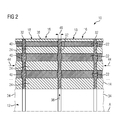
- an insert washer 32 is arranged between the individual layers 16 in each case or every second or every third layer. To make the washer 32 easier to see, is in FIG. 2 the rotor 10 is shown greatly enlarged, so that only two of the rotor laminations 18 are shown.
- the rotor continues in the axial direction along the axis of rotation A beyond break lines 34.
- the washers 32 do not have the recesses 22, as the rotor plates 18. They extend in the radial direction 36 perpendicular to the axis of rotation A continuously from the shaft of the Reduktanzmaschine to an outer edge 38 of the laminated core 14. The Einlegusionn 32 thus bridge the through holes 22.
- the washers 32 are fixedly connected to the Flußleitabitesen 24. By means of the washers 32, a centrifugal force acting on the individual flux guide sections 24 can be transmitted to the shaft of the electric machine during a rotation of the rotor 10 along the radial direction 36, ie radially inward.
- a thickness of the washers 32 in the axial direction is preferably less than 0.1 mm.
- Each insert 32 may for example be formed of an adhesive film, which may also be reinforced, for example, by glass fibers or carbon fibers. It can be provided as a washer 32 and a non-woven or fabric of fibers, which are preferably formed of glass or carbon fibers. The non-woven or fabric may then, after it has been arranged in stacking the rotor laminations 18 between them, have been interspersed by pouring or impregnating with a synthetic resin.
- the washers 32 swell, so that bulges 40 form in the recesses 22, in which the insert 32 in the axial direction along the axis of rotation A has a larger diameter, that is thicker than between the Flussleitabroughen 24.
- Another, very suitable Material for providing the washers 32 is the fabric available under the product name "Prepreg "® from Lange-Ritter. It is a reinforcing fiber that is already impregnated with resin. Upon heating the fiber, the resin liquefies for a short time and soaks the fibers before it starts to harden.
- Prepreg a reinforcing fiber that is already impregnated with resin. Upon heating the fiber, the resin liquefies for a short time and soaks the fibers before it starts to harden.
- Another, very suitable fabric is glass fiber fabric or glass fabric, as offered for example by the company HexForce ®.
- the laminated core 40 When the laminated core 40 is produced, when the synthetic resin in the washers 32 is still liquid, axial contact forces 44 can be applied to the laminated core 14, so that the rotor laminations 18 remain arranged at a desired distance from one another, while the contact washers 32 in the region of the beads 40 swell.
- the beads 40 have the advantage that forms a positive connection during clamping of the laminated core 14 under tension.
- Particularly stable is the laminated core when the recesses 22 are also filled with the resin.
- resin for example, water-thin cast resin can be used, which can penetrate through the washers 32 into the cavities between the Flußleitabitesen 24.
- the flux guide sections 24 are thereby fixed to one another with the insert disks 32.
- pouring or impregnating resin penetrating through capital action additionally forms the positive connection at the beads 40.
- the optimum adhesive gap, ie the distance 46 of the flux conducting sections of adjacent rotor plates 18, is within the range of 0.1 mm.
- the strength of the inserts should be as small as possible, but allow penetration of the potting compound (resin) by capillary action. Strengths in the range of 20 ⁇ m to 40 ⁇ m are considered optimum.
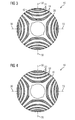
- FIG. 3 shows alternative embodiments of rotors in which individual magnetic layers 16 are formed differently. These embodiments have the advantage that the magnetic flux guidance necessary for the formation of the reluctance is influenced to a lesser extent than in the case of the rotor 10 by supporting elements, such as the webs 26 and the ring 28. For better orientation are in 3 and FIG. 4 Elements that correspond to elements in terms of their function, which in FIG. 1 or FIG. 2 are shown with the same reference numerals as in FIG. 1 or. FIG. 2 Provided.
- a magnetic layer 16 is a magnetic layer of a rotor in which a plurality of flux conducting portions 24 are provided, which are also separated from each other by the recesses 22, but which are held together solely by an outer ring 28.
- a non-magnetic region As formed by the recesses 22.
- FIG. 4 is a magnetic layer of a rotor shown, in which individual Flußleitabitese from separate rotor plates 18 'are formed, between which each non-magnetic areas 22', ie in particular air or resin are.
- a rotor with magnetic layers 16, as in FIG. 4 can be formed, for example, from a rotor with a magnetic layer, as shown in FIG FIG. 3 is shown.
- a rotor out FIG. 3 is removed by a machining process of the outer ring 28, after the individual magnetic layers through the washers 32 with each other are fixed, one obtains a rotor with a magnetic layer 16, as in FIG. 4 is shown.
- the examples show how to obtain the following advantages in a reluctance motor. It increases the speed suitability of the rotor 10.
- the necessary for adapting the outer diameter of the rotor 10 to a stator machining on the outer diameter of the rotor 10 is simpler by the increased stability of the laminated core 14 and can thus be carried out more cheaply. Since a bandage for stabilizing the laminated core 14, which has to be wound around the laminated core 14, can be dispensed with, an optimized air gap results in the reluctance motor.
- the washers 32 can also be used as the described electrical insulation of the individual sheets 18 to each other. Then the rotor plates 18 need not be additionally painted.
- the laminated core 14 of the rotor 10 has an improved bending natural frequency on the rotor through the entire composite, as a result of which the rotor laminated core 14 is also suitable for stabilizing the shaft of the reluctance motor. This also results in a reduction of the torsional vibrations during operation of the reluctance motor.
- a modular speed suitability can be set. For maximum stability, an inlay washer should be provided between all layers 16, for a lower speed rating it is sufficient to insert discs between every other or even between every third and fourth layer.
- an electrical machine 50 is shown, which is preferably a reluctance motor.
- the axis of rotation A is also an axis of symmetry.
- the electric machine 50 is configured in particular as an electric drive motor for a motor vehicle, in particular a motor vehicle.
- the electric machine 50 comprises a stator 52 in which windings 54 of electric coils are arranged, wherein FIG. 5 only one of the windings 54 is shown.
- the windings 54 are alternately energized by a converter C, whereby in the interior of the stator 52, a magnetic rotating field in an air gap 56 of the electric machine 50 is formed.
- Inside the stator 52 is a rotor 58 which is rotatably connected to a shaft 60.
- the shaft 60 is rotatably supported in the stator 52 about a rotation axis A.
- the rotor 58 is an embodiment of the rotor according to the invention, for example the rotor 10.
- FIG. 6 is shown in a schematic representation of a motor vehicle 62, which may be, for example, a passenger car.
- the motor vehicle 62 has an electric drive motor 64, in whose housing 66, for example, the electric machine 50 or another embodiment of the electric machine according to the invention can be located.
- the shaft 60 of the electric machine 42 may, for example, be coupled to a drive train 68 of the motor vehicle 62.
- the powertrain 68 may, for example, drive a rear wheel 70 of the motor vehicle 62.
Landscapes
- Engineering & Computer Science (AREA)
- Power Engineering (AREA)
- Life Sciences & Earth Sciences (AREA)
- Sustainable Development (AREA)
- Sustainable Energy (AREA)
- Transportation (AREA)
- Mechanical Engineering (AREA)
- Synchronous Machinery (AREA)
- Iron Core Of Rotating Electric Machines (AREA)
Priority Applications (12)
| Application Number | Priority Date | Filing Date | Title |
|---|---|---|---|
| EP13163688.8A EP2793362B1 (fr) | 2013-04-15 | 2013-04-15 | Moteur à reluctance et rotor associé |
| PCT/EP2013/070274 WO2014166555A2 (fr) | 2013-04-12 | 2013-09-27 | Rotor à réluctance avec assistance de démarrage |
| CN201910710132.6A CN110365179B (zh) | 2013-04-12 | 2013-09-27 | 用于磁阻电机的转子以及电的驱动装置 |
| EP13774106.2A EP2965408B1 (fr) | 2013-04-12 | 2013-09-27 | Rotor à réluctance avec assistance de démarrage |
| CN201380075523.6A CN105144555A (zh) | 2013-04-12 | 2013-09-27 | 具有启动辅助的磁阻电机 |
| US14/783,509 US10284032B2 (en) | 2013-04-12 | 2013-09-27 | Reluctance rotor with runup aid |
| RU2015148539A RU2638826C2 (ru) | 2013-04-12 | 2013-09-27 | Реактивный ротор, имеющий пусковое вспомогательное устройство |
| RU2015148194A RU2611583C1 (ru) | 2013-04-11 | 2014-02-28 | Синхронный реактивный электродвигатель и соответствующий ротор |
| US14/783,498 US10090719B2 (en) | 2013-04-11 | 2014-02-28 | Reluctance motor and associated rotor |
| CN201480020778.7A CN105122595B (zh) | 2013-04-11 | 2014-02-28 | 磁阻电动机和附属的转子 |
| BR112015025611A BR112015025611A2 (pt) | 2013-04-11 | 2014-02-28 | rotor para um motor de relutância, motor de relutância, veículo motorizado, e, método para fabricar um rotor |
| PCT/EP2014/053981 WO2014166674A2 (fr) | 2013-04-11 | 2014-02-28 | Moteur à réluctance et rotor correspondant |
Applications Claiming Priority (1)
| Application Number | Priority Date | Filing Date | Title |
|---|---|---|---|
| EP13163688.8A EP2793362B1 (fr) | 2013-04-15 | 2013-04-15 | Moteur à reluctance et rotor associé |
Publications (2)
| Publication Number | Publication Date |
|---|---|
| EP2793362A1 true EP2793362A1 (fr) | 2014-10-22 |
| EP2793362B1 EP2793362B1 (fr) | 2015-06-17 |
Family
ID=48095710
Family Applications (1)
| Application Number | Title | Priority Date | Filing Date |
|---|---|---|---|
| EP13163688.8A Active EP2793362B1 (fr) | 2013-04-11 | 2013-04-15 | Moteur à reluctance et rotor associé |
Country Status (1)
| Country | Link |
|---|---|
| EP (1) | EP2793362B1 (fr) |
Cited By (4)
| Publication number | Priority date | Publication date | Assignee | Title |
|---|---|---|---|---|
| CN107210659A (zh) * | 2015-03-19 | 2017-09-26 | 西门子公司 | 同步磁阻电机的转子 |
| US10284032B2 (en) | 2013-04-12 | 2019-05-07 | Siemens Aktiengesellschaft | Reluctance rotor with runup aid |
| EP3595136A1 (fr) * | 2018-07-13 | 2020-01-15 | Siemens Aktiengesellschaft | Couches de matériau robustes |
| DE102021127354A1 (de) | 2021-10-21 | 2023-04-27 | Schaeffler Technologies AG & Co. KG | Rotor mit innengekühlten Rotorstacks |
Families Citing this family (1)
| Publication number | Priority date | Publication date | Assignee | Title |
|---|---|---|---|---|
| DE102023115829A1 (de) * | 2023-06-16 | 2024-12-19 | Schaeffler Technologies AG & Co. KG | Rotor und elektrische Maschine |
Citations (7)
| Publication number | Priority date | Publication date | Assignee | Title |
|---|---|---|---|---|
| EP0141187A1 (fr) * | 1983-09-14 | 1985-05-15 | Stahlwerke Bochum AG | Tôle pour noyaux de fer feuilletés |
| US5801478A (en) * | 1994-05-02 | 1998-09-01 | Okuma Corporation | Reluctance type synchronous motor |
| US5818140A (en) | 1995-07-11 | 1998-10-06 | Vagati; Alfredo | Synchronous reluctance electrical motor having a low torque-ripple design |
| WO1999033156A1 (fr) * | 1997-12-19 | 1999-07-01 | Minnesota Mining And Manufacturing Company | Stator, rotor et transformateur amortis interieurement et leur procede de production |
| WO2011018119A1 (fr) * | 2009-08-14 | 2011-02-17 | Abb Research Ltd. | Rotor modulaire pour machine synchrone à reluctance |
| EP2442432A2 (fr) * | 2010-10-12 | 2012-04-18 | ABB Oy | Rotor pour une machine synchrone à réluctance et procédé de fabrication du rotor d'une machine synchrone à réluctance |
| DE102011079843A1 (de) * | 2011-07-26 | 2013-01-31 | Siemens Aktiengesellschaft | Elektrische Maschine mit massenarmer Bauart in magnetisch aktiven Teilen |
-
2013
- 2013-04-15 EP EP13163688.8A patent/EP2793362B1/fr active Active
Patent Citations (7)
| Publication number | Priority date | Publication date | Assignee | Title |
|---|---|---|---|---|
| EP0141187A1 (fr) * | 1983-09-14 | 1985-05-15 | Stahlwerke Bochum AG | Tôle pour noyaux de fer feuilletés |
| US5801478A (en) * | 1994-05-02 | 1998-09-01 | Okuma Corporation | Reluctance type synchronous motor |
| US5818140A (en) | 1995-07-11 | 1998-10-06 | Vagati; Alfredo | Synchronous reluctance electrical motor having a low torque-ripple design |
| WO1999033156A1 (fr) * | 1997-12-19 | 1999-07-01 | Minnesota Mining And Manufacturing Company | Stator, rotor et transformateur amortis interieurement et leur procede de production |
| WO2011018119A1 (fr) * | 2009-08-14 | 2011-02-17 | Abb Research Ltd. | Rotor modulaire pour machine synchrone à reluctance |
| EP2442432A2 (fr) * | 2010-10-12 | 2012-04-18 | ABB Oy | Rotor pour une machine synchrone à réluctance et procédé de fabrication du rotor d'une machine synchrone à réluctance |
| DE102011079843A1 (de) * | 2011-07-26 | 2013-01-31 | Siemens Aktiengesellschaft | Elektrische Maschine mit massenarmer Bauart in magnetisch aktiven Teilen |
Cited By (7)
| Publication number | Priority date | Publication date | Assignee | Title |
|---|---|---|---|---|
| US10284032B2 (en) | 2013-04-12 | 2019-05-07 | Siemens Aktiengesellschaft | Reluctance rotor with runup aid |
| CN107210659A (zh) * | 2015-03-19 | 2017-09-26 | 西门子公司 | 同步磁阻电机的转子 |
| US10404113B2 (en) | 2015-03-19 | 2019-09-03 | Siemens Aktiengesellschaft | Rotor of a synchronous reluctance machine |
| EP3595136A1 (fr) * | 2018-07-13 | 2020-01-15 | Siemens Aktiengesellschaft | Couches de matériau robustes |
| WO2020011820A1 (fr) * | 2018-07-13 | 2020-01-16 | Siemens Aktiengesellschaft | Couches de matériaux robustes |
| US12046951B2 (en) | 2018-07-13 | 2024-07-23 | Siemens Aktiengesellschaft | Method for producing a magnetic material layer |
| DE102021127354A1 (de) | 2021-10-21 | 2023-04-27 | Schaeffler Technologies AG & Co. KG | Rotor mit innengekühlten Rotorstacks |
Also Published As
| Publication number | Publication date |
|---|---|
| EP2793362B1 (fr) | 2015-06-17 |
Similar Documents
| Publication | Publication Date | Title |
|---|---|---|
| WO2014166674A2 (fr) | Moteur à réluctance et rotor correspondant | |
| EP2961039B1 (fr) | Rotor stabilisé mécaniquement pour un moteur à réluctance | |
| EP3292613B1 (fr) | Rotor a reluctance a magnetisation propre supplementaire | |
| EP2807726B1 (fr) | Rotor pour machine électrique tournante et moteur électrique | |
| EP2639935B1 (fr) | Rotor à excitation permanente, machine électrique dotée d'un tel rotor et procédé de fabrication du rotor | |
| EP3084936B1 (fr) | Rotor a reluctance comprenant une tole de rotor avec un evidement servant a reduire les tensions | |
| EP3103183B1 (fr) | Rotor à réluctance à stabilisation mécanique | |
| EP2820744B1 (fr) | Machine électrique tournante | |
| EP2766976B1 (fr) | Rotor en étoile à géométrie intérieure optimisée | |
| DE102008032844A1 (de) | Permanentmagnetischer Rotor | |
| EP2793362B1 (fr) | Moteur à reluctance et rotor associé | |
| EP2790296A1 (fr) | Moteur à reluctance doté d'un rotor stabilisé | |
| DE102011050094A1 (de) | Rotor für eine drehende elektrische Maschine | |
| DE102014111241A1 (de) | Blech- oder Sinterteil für einen Stator oder einen Läufer einer elektrischen Maschine sowie Verfahren zu dessen Herstellung | |
| DE102022112346A1 (de) | Rotor für eine elektrische maschine, elektrische maschine für ein fahrzeug, und fahrzeug | |
| EP3381107B1 (fr) | Tole electrique dotee d'une ame imprimee | |
| EP2790295A1 (fr) | Rotor pour un moteur à reluctance, procédé de fabrication d'un rotor pour un moteur à reluctance et machine électrique, notamment moteur à reluctance | |
| EP3167537B1 (fr) | Rotor doté d'arêtes dépassant vers l'intérieur | |
| DE102023200649A1 (de) | Rotor für einen axialflussmotor | |
| DE102021130152A1 (de) | Rotor für eine Axialfluss-permanenterregte Synchronmaschine und Axialfluss-permanenterregte Synchronmaschine | |
| WO2014166826A2 (fr) | Moteur à réluctance à rotor stabilisé | |
| WO2011091791A2 (fr) | Élément de fixation pour fixer un aimant sur un composant d'une machine électrique, module et composant doté d'un élément de fixation de ce type | |
| DE102020126339A1 (de) | Magnetische Einheit einer rotierenden elektrischen Maschine | |
| DE102021211716A1 (de) | Rotoranordnung für eine elektrische Maschine | |
| EP3076520A1 (fr) | Rotor de machine électrique et procédé de production |
Legal Events
| Date | Code | Title | Description |
|---|---|---|---|
| PUAI | Public reference made under article 153(3) epc to a published international application that has entered the european phase |
Free format text: ORIGINAL CODE: 0009012 |
|
| 17P | Request for examination filed |
Effective date: 20140219 |
|
| AK | Designated contracting states |
Kind code of ref document: A1 Designated state(s): AL AT BE BG CH CY CZ DE DK EE ES FI FR GB GR HR HU IE IS IT LI LT LU LV MC MK MT NL NO PL PT RO RS SE SI SK SM TR |
|
| AX | Request for extension of the european patent |
Extension state: BA ME |
|
| RIC1 | Information provided on ipc code assigned before grant |
Ipc: H02K 1/24 20060101AFI20141028BHEP Ipc: H02K 15/02 20060101ALN20141028BHEP |
|
| GRAP | Despatch of communication of intention to grant a patent |
Free format text: ORIGINAL CODE: EPIDOSNIGR1 |
|
| INTG | Intention to grant announced |
Effective date: 20150108 |
|
| GRAS | Grant fee paid |
Free format text: ORIGINAL CODE: EPIDOSNIGR3 |
|
| GRAA | (expected) grant |
Free format text: ORIGINAL CODE: 0009210 |
|
| AK | Designated contracting states |
Kind code of ref document: B1 Designated state(s): AL AT BE BG CH CY CZ DE DK EE ES FI FR GB GR HR HU IE IS IT LI LT LU LV MC MK MT NL NO PL PT RO RS SE SI SK SM TR |
|
| REG | Reference to a national code |
Ref country code: GB Ref legal event code: FG4D Free format text: NOT ENGLISH |
|
| REG | Reference to a national code |
Ref country code: CH Ref legal event code: EP |
|
| REG | Reference to a national code |
Ref country code: AT Ref legal event code: REF Ref document number: 732374 Country of ref document: AT Kind code of ref document: T Effective date: 20150715 |
|
| REG | Reference to a national code |
Ref country code: IE Ref legal event code: FG4D Free format text: LANGUAGE OF EP DOCUMENT: GERMAN |
|
| REG | Reference to a national code |
Ref country code: DE Ref legal event code: R096 Ref document number: 502013000753 Country of ref document: DE |
|
| REG | Reference to a national code |
Ref country code: SE Ref legal event code: TRGR |
|
| PG25 | Lapsed in a contracting state [announced via postgrant information from national office to epo] |
Ref country code: LT Free format text: LAPSE BECAUSE OF FAILURE TO SUBMIT A TRANSLATION OF THE DESCRIPTION OR TO PAY THE FEE WITHIN THE PRESCRIBED TIME-LIMIT Effective date: 20150617 Ref country code: FI Free format text: LAPSE BECAUSE OF FAILURE TO SUBMIT A TRANSLATION OF THE DESCRIPTION OR TO PAY THE FEE WITHIN THE PRESCRIBED TIME-LIMIT Effective date: 20150617 Ref country code: HR Free format text: LAPSE BECAUSE OF FAILURE TO SUBMIT A TRANSLATION OF THE DESCRIPTION OR TO PAY THE FEE WITHIN THE PRESCRIBED TIME-LIMIT Effective date: 20150617 Ref country code: NO Free format text: LAPSE BECAUSE OF FAILURE TO SUBMIT A TRANSLATION OF THE DESCRIPTION OR TO PAY THE FEE WITHIN THE PRESCRIBED TIME-LIMIT Effective date: 20150917 |
|
| REG | Reference to a national code |
Ref country code: LT Ref legal event code: MG4D Ref country code: NL Ref legal event code: MP Effective date: 20150617 |
|
| PG25 | Lapsed in a contracting state [announced via postgrant information from national office to epo] |
Ref country code: BG Free format text: LAPSE BECAUSE OF FAILURE TO SUBMIT A TRANSLATION OF THE DESCRIPTION OR TO PAY THE FEE WITHIN THE PRESCRIBED TIME-LIMIT Effective date: 20150917 Ref country code: RS Free format text: LAPSE BECAUSE OF FAILURE TO SUBMIT A TRANSLATION OF THE DESCRIPTION OR TO PAY THE FEE WITHIN THE PRESCRIBED TIME-LIMIT Effective date: 20150617 Ref country code: LV Free format text: LAPSE BECAUSE OF FAILURE TO SUBMIT A TRANSLATION OF THE DESCRIPTION OR TO PAY THE FEE WITHIN THE PRESCRIBED TIME-LIMIT Effective date: 20150617 Ref country code: GR Free format text: LAPSE BECAUSE OF FAILURE TO SUBMIT A TRANSLATION OF THE DESCRIPTION OR TO PAY THE FEE WITHIN THE PRESCRIBED TIME-LIMIT Effective date: 20150918 |
|
| PG25 | Lapsed in a contracting state [announced via postgrant information from national office to epo] |
Ref country code: EE Free format text: LAPSE BECAUSE OF FAILURE TO SUBMIT A TRANSLATION OF THE DESCRIPTION OR TO PAY THE FEE WITHIN THE PRESCRIBED TIME-LIMIT Effective date: 20150617 |
|
| PG25 | Lapsed in a contracting state [announced via postgrant information from national office to epo] |
Ref country code: RO Free format text: LAPSE BECAUSE OF NON-PAYMENT OF DUE FEES Effective date: 20150617 Ref country code: CZ Free format text: LAPSE BECAUSE OF FAILURE TO SUBMIT A TRANSLATION OF THE DESCRIPTION OR TO PAY THE FEE WITHIN THE PRESCRIBED TIME-LIMIT Effective date: 20150617 Ref country code: IS Free format text: LAPSE BECAUSE OF FAILURE TO SUBMIT A TRANSLATION OF THE DESCRIPTION OR TO PAY THE FEE WITHIN THE PRESCRIBED TIME-LIMIT Effective date: 20151017 Ref country code: SK Free format text: LAPSE BECAUSE OF FAILURE TO SUBMIT A TRANSLATION OF THE DESCRIPTION OR TO PAY THE FEE WITHIN THE PRESCRIBED TIME-LIMIT Effective date: 20150617 Ref country code: ES Free format text: LAPSE BECAUSE OF FAILURE TO SUBMIT A TRANSLATION OF THE DESCRIPTION OR TO PAY THE FEE WITHIN THE PRESCRIBED TIME-LIMIT Effective date: 20150617 Ref country code: PL Free format text: LAPSE BECAUSE OF FAILURE TO SUBMIT A TRANSLATION OF THE DESCRIPTION OR TO PAY THE FEE WITHIN THE PRESCRIBED TIME-LIMIT Effective date: 20150617 Ref country code: PT Free format text: LAPSE BECAUSE OF FAILURE TO SUBMIT A TRANSLATION OF THE DESCRIPTION OR TO PAY THE FEE WITHIN THE PRESCRIBED TIME-LIMIT Effective date: 20151019 |
|
| REG | Reference to a national code |
Ref country code: DE Ref legal event code: R097 Ref document number: 502013000753 Country of ref document: DE |
|
| PLBE | No opposition filed within time limit |
Free format text: ORIGINAL CODE: 0009261 |
|
| STAA | Information on the status of an ep patent application or granted ep patent |
Free format text: STATUS: NO OPPOSITION FILED WITHIN TIME LIMIT |
|
| PG25 | Lapsed in a contracting state [announced via postgrant information from national office to epo] |
Ref country code: DK Free format text: LAPSE BECAUSE OF FAILURE TO SUBMIT A TRANSLATION OF THE DESCRIPTION OR TO PAY THE FEE WITHIN THE PRESCRIBED TIME-LIMIT Effective date: 20150617 |
|
| REG | Reference to a national code |
Ref country code: FR Ref legal event code: PLFP Year of fee payment: 4 |
|
| 26N | No opposition filed |
Effective date: 20160318 |
|
| PG25 | Lapsed in a contracting state [announced via postgrant information from national office to epo] |
Ref country code: SI Free format text: LAPSE BECAUSE OF FAILURE TO SUBMIT A TRANSLATION OF THE DESCRIPTION OR TO PAY THE FEE WITHIN THE PRESCRIBED TIME-LIMIT Effective date: 20150617 |
|
| REG | Reference to a national code |
Ref country code: CH Ref legal event code: PL |
|
| PG25 | Lapsed in a contracting state [announced via postgrant information from national office to epo] |
Ref country code: LU Free format text: LAPSE BECAUSE OF FAILURE TO SUBMIT A TRANSLATION OF THE DESCRIPTION OR TO PAY THE FEE WITHIN THE PRESCRIBED TIME-LIMIT Effective date: 20160415 |
|
| REG | Reference to a national code |
Ref country code: IE Ref legal event code: MM4A |
|
| PG25 | Lapsed in a contracting state [announced via postgrant information from national office to epo] |
Ref country code: CH Free format text: LAPSE BECAUSE OF NON-PAYMENT OF DUE FEES Effective date: 20160430 Ref country code: LI Free format text: LAPSE BECAUSE OF NON-PAYMENT OF DUE FEES Effective date: 20160430 |
|
| REG | Reference to a national code |
Ref country code: FR Ref legal event code: PLFP Year of fee payment: 5 |
|
| PG25 | Lapsed in a contracting state [announced via postgrant information from national office to epo] |
Ref country code: IE Free format text: LAPSE BECAUSE OF NON-PAYMENT OF DUE FEES Effective date: 20160415 |
|
| PG25 | Lapsed in a contracting state [announced via postgrant information from national office to epo] |
Ref country code: NL Free format text: LAPSE BECAUSE OF FAILURE TO SUBMIT A TRANSLATION OF THE DESCRIPTION OR TO PAY THE FEE WITHIN THE PRESCRIBED TIME-LIMIT Effective date: 20150617 |
|
| GBPC | Gb: european patent ceased through non-payment of renewal fee |
Effective date: 20170415 |
|
| PG25 | Lapsed in a contracting state [announced via postgrant information from national office to epo] |
Ref country code: GB Free format text: LAPSE BECAUSE OF NON-PAYMENT OF DUE FEES Effective date: 20170415 |
|
| REG | Reference to a national code |
Ref country code: FR Ref legal event code: PLFP Year of fee payment: 6 |
|
| PG25 | Lapsed in a contracting state [announced via postgrant information from national office to epo] |
Ref country code: HU Free format text: LAPSE BECAUSE OF FAILURE TO SUBMIT A TRANSLATION OF THE DESCRIPTION OR TO PAY THE FEE WITHIN THE PRESCRIBED TIME-LIMIT; INVALID AB INITIO Effective date: 20130415 Ref country code: SM Free format text: LAPSE BECAUSE OF FAILURE TO SUBMIT A TRANSLATION OF THE DESCRIPTION OR TO PAY THE FEE WITHIN THE PRESCRIBED TIME-LIMIT Effective date: 20150617 |
|
| PG25 | Lapsed in a contracting state [announced via postgrant information from national office to epo] |
Ref country code: CY Free format text: LAPSE BECAUSE OF FAILURE TO SUBMIT A TRANSLATION OF THE DESCRIPTION OR TO PAY THE FEE WITHIN THE PRESCRIBED TIME-LIMIT Effective date: 20150617 Ref country code: MK Free format text: LAPSE BECAUSE OF FAILURE TO SUBMIT A TRANSLATION OF THE DESCRIPTION OR TO PAY THE FEE WITHIN THE PRESCRIBED TIME-LIMIT Effective date: 20150617 Ref country code: MT Free format text: LAPSE BECAUSE OF FAILURE TO SUBMIT A TRANSLATION OF THE DESCRIPTION OR TO PAY THE FEE WITHIN THE PRESCRIBED TIME-LIMIT Effective date: 20150617 Ref country code: MC Free format text: LAPSE BECAUSE OF FAILURE TO SUBMIT A TRANSLATION OF THE DESCRIPTION OR TO PAY THE FEE WITHIN THE PRESCRIBED TIME-LIMIT Effective date: 20150617 |
|
| PGFP | Annual fee paid to national office [announced via postgrant information from national office to epo] |
Ref country code: RO Payment date: 20180530 Year of fee payment: 11 |
|
| PG25 | Lapsed in a contracting state [announced via postgrant information from national office to epo] |
Ref country code: TR Free format text: LAPSE BECAUSE OF FAILURE TO SUBMIT A TRANSLATION OF THE DESCRIPTION OR TO PAY THE FEE WITHIN THE PRESCRIBED TIME-LIMIT Effective date: 20150617 Ref country code: AL Free format text: LAPSE BECAUSE OF FAILURE TO SUBMIT A TRANSLATION OF THE DESCRIPTION OR TO PAY THE FEE WITHIN THE PRESCRIBED TIME-LIMIT Effective date: 20150617 |
|
| REG | Reference to a national code |
Ref country code: AT Ref legal event code: MM01 Ref document number: 732374 Country of ref document: AT Kind code of ref document: T Effective date: 20180415 |
|
| PG25 | Lapsed in a contracting state [announced via postgrant information from national office to epo] |
Ref country code: AT Free format text: LAPSE BECAUSE OF NON-PAYMENT OF DUE FEES Effective date: 20180415 |
|
| REG | Reference to a national code |
Ref country code: BE Ref legal event code: MM Effective date: 20190430 |
|
| PG25 | Lapsed in a contracting state [announced via postgrant information from national office to epo] |
Ref country code: BE Free format text: LAPSE BECAUSE OF NON-PAYMENT OF DUE FEES Effective date: 20190430 |
|
| PGFP | Annual fee paid to national office [announced via postgrant information from national office to epo] |
Ref country code: SE Payment date: 20200407 Year of fee payment: 8 |
|
| REG | Reference to a national code |
Ref country code: SE Ref legal event code: EUG |
|
| PG25 | Lapsed in a contracting state [announced via postgrant information from national office to epo] |
Ref country code: SE Free format text: LAPSE BECAUSE OF NON-PAYMENT OF DUE FEES Effective date: 20210416 |
|
| PGFP | Annual fee paid to national office [announced via postgrant information from national office to epo] |
Ref country code: FR Payment date: 20220414 Year of fee payment: 10 |
|
| PG25 | Lapsed in a contracting state [announced via postgrant information from national office to epo] |
Ref country code: FR Free format text: LAPSE BECAUSE OF NON-PAYMENT OF DUE FEES Effective date: 20230430 |
|
| PGFP | Annual fee paid to national office [announced via postgrant information from national office to epo] |
Ref country code: DE Payment date: 20250429 Year of fee payment: 13 |
|
| PGFP | Annual fee paid to national office [announced via postgrant information from national office to epo] |
Ref country code: IT Payment date: 20250327 Year of fee payment: 13 |
|
| REG | Reference to a national code |
Ref country code: DE Ref legal event code: R081 Ref document number: 502013000753 Country of ref document: DE Owner name: INNOMOTICS GMBH, DE Free format text: FORMER OWNER: SIEMENS AKTIENGESELLSCHAFT, 80333 MUENCHEN, DE |