EP2795208B1 - Système d'alimentation pour système de réfrigération de transport - Google Patents
Système d'alimentation pour système de réfrigération de transport Download PDFInfo
- Publication number
- EP2795208B1 EP2795208B1 EP12808583.4A EP12808583A EP2795208B1 EP 2795208 B1 EP2795208 B1 EP 2795208B1 EP 12808583 A EP12808583 A EP 12808583A EP 2795208 B1 EP2795208 B1 EP 2795208B1
- Authority
- EP
- European Patent Office
- Prior art keywords
- transport refrigeration
- engine
- refrigerant
- refrigeration system
- fan
- Prior art date
- Legal status (The legal status is an assumption and is not a legal conclusion. Google has not performed a legal analysis and makes no representation as to the accuracy of the status listed.)
- Not-in-force
Links
Images

Classifications
-
- F—MECHANICAL ENGINEERING; LIGHTING; HEATING; WEAPONS; BLASTING
- F25—REFRIGERATION OR COOLING; COMBINED HEATING AND REFRIGERATION SYSTEMS; HEAT PUMP SYSTEMS; MANUFACTURE OR STORAGE OF ICE; LIQUEFACTION SOLIDIFICATION OF GASES
- F25B—REFRIGERATION MACHINES, PLANTS OR SYSTEMS; COMBINED HEATING AND REFRIGERATION SYSTEMS; HEAT PUMP SYSTEMS
- F25B27/00—Machines, plants or systems, using particular sources of energy
- F25B27/02—Machines, plants or systems, using particular sources of energy using waste heat, e.g. from internal-combustion engines
-
- B—PERFORMING OPERATIONS; TRANSPORTING
- B60—VEHICLES IN GENERAL
- B60P—VEHICLES ADAPTED FOR LOAD TRANSPORTATION OR TO TRANSPORT, TO CARRY, OR TO COMPRISE SPECIAL LOADS OR OBJECTS
- B60P3/00—Vehicles adapted to transport, to carry or to comprise special loads or objects
- B60P3/20—Refrigerated goods vehicles
-
- F—MECHANICAL ENGINEERING; LIGHTING; HEATING; WEAPONS; BLASTING
- F01—MACHINES OR ENGINES IN GENERAL; ENGINE PLANTS IN GENERAL; STEAM ENGINES
- F01N—GAS-FLOW SILENCERS OR EXHAUST APPARATUS FOR MACHINES OR ENGINES IN GENERAL; GAS-FLOW SILENCERS OR EXHAUST APPARATUS FOR INTERNAL-COMBUSTION ENGINES
- F01N5/00—Exhaust or silencing apparatus combined or associated with devices profiting by exhaust energy
- F01N5/02—Exhaust or silencing apparatus combined or associated with devices profiting by exhaust energy the devices using heat
- F01N5/025—Exhaust or silencing apparatus combined or associated with devices profiting by exhaust energy the devices using heat the device being thermoelectric generators
-
- F—MECHANICAL ENGINEERING; LIGHTING; HEATING; WEAPONS; BLASTING
- F25—REFRIGERATION OR COOLING; COMBINED HEATING AND REFRIGERATION SYSTEMS; HEAT PUMP SYSTEMS; MANUFACTURE OR STORAGE OF ICE; LIQUEFACTION SOLIDIFICATION OF GASES
- F25D—REFRIGERATORS; COLD ROOMS; ICE-BOXES; COOLING OR FREEZING APPARATUS NOT OTHERWISE PROVIDED FOR
- F25D11/00—Self-contained movable devices, e.g. domestic refrigerators
- F25D11/003—Transport containers
-
- Y—GENERAL TAGGING OF NEW TECHNOLOGICAL DEVELOPMENTS; GENERAL TAGGING OF CROSS-SECTIONAL TECHNOLOGIES SPANNING OVER SEVERAL SECTIONS OF THE IPC; TECHNICAL SUBJECTS COVERED BY FORMER USPC CROSS-REFERENCE ART COLLECTIONS [XRACs] AND DIGESTS
- Y02—TECHNOLOGIES OR APPLICATIONS FOR MITIGATION OR ADAPTATION AGAINST CLIMATE CHANGE
- Y02T—CLIMATE CHANGE MITIGATION TECHNOLOGIES RELATED TO TRANSPORTATION
- Y02T10/00—Road transport of goods or passengers
- Y02T10/10—Internal combustion engine [ICE] based vehicles
- Y02T10/12—Improving ICE efficiencies
Definitions
- This invention relates generally to transport refrigeration systems for refrigerating perishable cargo during transit and, more particularly, to on-board power supply systems for providing electrical power to various components of the transport refrigeration unit.
- Refrigerated trucks and trailers are commonly used to transport perishable cargo, such as, for example, produce, meat, poultry, fish, dairy products, cut flowers, and other fresh or frozen perishable products stowed in a temperature-controlled space, commonly referred to as the cargo box, within the truck or trailer.
- a transport refrigeration system is mounted to the truck, typically behind the truck or on the roof of the truck, for maintaining a controlled temperature environment within the cargo box of the truck.
- a transport refrigeration system is mounted to the trailer, typically to the front wall of the trailer, for maintaining a controlled temperature environment within the cargo box of the trailer.
- transport refrigeration systems used in connection with refrigerated trucks and refrigerated trailers include a transport refrigeration unit having a refrigerant compressor, a condenser with one or more associated condenser fans, an expansion device, and an evaporator with one or more associated evaporator fans, which are connected via appropriate refrigerant lines in a closed refrigerant flow circuit.
- Air or an air/gas mixture is drawn from the interior volume of the cargo box by the evaporator fan(s) associated with the evaporator, passed through the airside of the evaporator in heat exchange relationship with refrigerant whereby the refrigerant absorbs heat from the air, thereby cooling the air.
- the cooled air is then supplied back to the cargo box.
- the compressor On commercially available transport refrigeration systems used in connection with refrigerated trucks and refrigerated trailers, the compressor, and typically other components of the transport refrigeration unit, must be powered during transit by a prime mover.
- the prime mover typically comprises a diesel engine carried on and considered part of the transport refrigeration system.
- the compressor In mechanically driven transport refrigeration systems the compressor is directly driven by the diesel engine, either through a direct mechanical coupling or a belt drive, and other components, such as the condenser fan(s) and evaporator fan(s) are belt driven.
- a low voltage unit battery may also be provided to power electronic equipment, such as a system controller and other control system components, as well as lighting associated with the transport refrigeration system.
- An alternator, belt driven off the diesel engine is typically provided for charging the low voltage unit battery.
- An all electric transport refrigeration system for refrigerated trailer application is also commercially available through Carrier Corporation headquartered in Farmington, Connecticut, USA.
- a prime mover most commonly a diesel engine, carried on and considered part of the transport refrigeration system, drives an AC synchronous generator that generates AC power.
- the generated AC power is used to power an electric compressor motor for driving the refrigerant compressor of the transport refrigeration unit and also powering electric AC fan motors for driving the condenser and evaporator motors and electric heaters associated with the evaporator.
- U.S. Pat. No. 6,223,546 discloses an all electric transport refrigeration system.
- a low voltage unit battery may also be provided to power electronic equipment, such as a system controller and other control system components, as well as lighting associated with the transport refrigeration system.
- a transport refrigeration unit installed on a refrigerated truck or trailer operates in one of a temperature pulldown mode, a temperature maintenance mode, or a standstill mode.
- the refrigerant compressor, the condenser fan(s) and the evaporator fan(s) are operating with the refrigerant compressor generally operating at full capacity to lower the temperature within the cargo space as rapidly as possible to a desired set point temperature appropriate for the particular cargo stowed in the cargo space.
- the refrigerant compressor, the condenser fan(s) and the evaporator fan(s) are still operating, but the refrigerant compressor is operating at a significantly lower capacity so as to maintain the temperature in the cargo space within a specified range of the desired set point temperature and avoid over cooling.
- heaters associated with the evaporator may also be activated as necessary to warm the air passed through the evaporators by the evaporator fan(s) to prevent over cooling.
- the refrigerant compressor and the condenser and evaporator fans are off.
- Diesel engines used as prime movers on transport refrigeration systems generally have two operating speeds, that is a high RPM speed, such as 2200 RPM, and a low RPM speed, such as 1400 RPM.
- the diesel engine In operation, the diesel engine is operated at high speed during temperature pulldown and other heavy refrigeration load conditions and at low speed during the temperature maintenance mode. During standstill, the diesel engine is typically idling at low speed.
- the diesel engine is generally designed to meet the power needs of the transport refrigeration unit during operation at maximum capacity, such as during the temperature pulldown mode, with efficient fuel consumption. Therefore, during the temperature maintenance mode and standstill mode, the diesel engine is operating at lower efficiency and with increased fuel consumption.
- a transport refrigeration system is provided according to independent claim 1.
- a method is also provided for augmenting power generation of a power supply system of a transport refrigeration in accordance with independent method claim 12.
- US 6 223 546 B1 shows a transport refrigeration unit of the type configured to be mounted on the front wall of a transport trailer, the transport trailer being adapted to be connected to and towed by a motorized tractor, the transport refrigeration unit comprising a compressor having a discharge port and a suction port and further having an electric compressor drive motor hermetically disposed therein for running the compressor, a condenser heat exchanger unit operatively coupled to said compressor discharge port, an evaporator heat exchanger unit operatively coupled to said compressor suction port, at least one fan assembly having at least one electric fan motor configured to provide air flow over one of said heat exchanger units and an integrally mounted unitary engine driven generator assembly configured to selectively produce at least one A.C. voltage at one or more frequencies, wherein said generator assembly is configured to produce sufficient electric power to operate said compressor drive motor and said at least one fan motor.
- WO 2010/112958 A1 shows an internal combustion engine arrangement comprising an exhaust line capable of collecting exhaust gas from the internal combustion engine, said exhaust line including a particulate filter, active regenerating means capable of generating heat during a regeneration period so as to promote oxidation of the particles retained in said filter, a thermoelectric device capable of producing electricity by Seebeck effect by the conversion of a heat flux between the hot exhaust gases flowing in the exhaust line and a cold source, said thermoelectric device being located downstream from said filter.
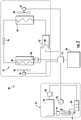
- the transport refrigeration systems 20 depicted in FIGs. 1 and 2 include a refrigeration unit 22, an onboard power supply system 24 that includes a fossil-fueled engine 26, typically a diesel engine, a storage battery 28 and a thermoelectric generator 30, and a controller 70.
- the refrigeration unit 22 functions, under the control of the controller 70, to establish and regulate a desired product storage temperature within a refrigerated cargo space wherein a perishable product is stored during transport and to maintain the product storage temperature within a specified temperature range.
- the refrigerated cargo space may be the cargo box of a trailer, a truck, or an intermodal container wherein perishable cargo, such as, for example, produce, meat, poultry, fish, dairy products, cut flowers, and other fresh or frozen perishable cargo, is stowed for transport.
- the transport refrigeration unit 22 includes a refrigerant compression device 32, a refrigerant heat rejection heat exchanger 34, an expansion device 36, and a refrigerant heat absorption heat exchanger 38 connected in refrigerant flow communication in a closed loop refrigerant circuit and arranged in a conventional refrigeration cycle.
- the refrigeration unit 22 also includes one or more fans 40 associated with the refrigerant heat rejection heat exchanger 34 and driven by fan motor(s) 42 mounted to shaft(s) 43, and one or more fans 44 associated with the refrigerant heat absorption heat exchanger 38 and driven by fan motor(s) 46 mounted to shaft(s) 45.
- the refrigeration unit 22 may also include an electric resistance heater 48 associated with the refrigerant heat absorption heat exchanger 38. It is to be understood that other components (not shown) may be incorporated into the refrigerant circuit as desired, including for example, but not limited to, a suction modulation valve, a receiver, a filter/dryer, an economizer circuit.
- the refrigerant heat rejection heat exchanger 34 may, for example, comprise one or more refrigerant conveying coiled tubes or one or more tube banks formed of a plurality of refrigerant conveying tubes extending between respective inlet and outlet manifolds.
- the fan(s) 40 are operative to pass a cooling fluid, typically ambient air, across the tubes of the refrigerant heat rejection heat exchanger 34 to cool refrigerant vapor passing through the tubes.
- the refrigerant heat rejection heat exchanger 34 may operate either as a refrigerant condenser, such as if the refrigeration unit 22 is operating in a subcritical refrigerant cycle or as a refrigerant gas cooler, such as if the refrigeration unit 22 is operating in a transcritical cycle.
- the refrigerant heat absorption heat exchanger 38 may, for example, also comprise one or more refrigerant conveying coiled tubes or one or more tube banks formed of a plurality of refrigerant conveying tubes extending between respective inlet and outlet manifolds.
- the fan(s) 44 are operative to pass air drawn from the temperature controlled cargo box across the tubes of the refrigerant heat absorption heat exchanger 38 to heat and evaporate refrigerant liquid passing through the tubes and cool the air.
- the air cooled in traversing the refrigerant heat rejection heat exchanger 38 is supplied back to the temperature controlled cargo box.
- air when used herein with reference to the atmosphere within the cargo box includes mixtures of air with other gases, such as for example, but not limited to, nitrogen or carbon dioxide, sometimes introduced into a refrigerated cargo box for transport of perishable produce.
- the refrigerant compression device 32 may comprise a single-stage or multiple-stage compressor such as, for example, a reciprocating compressor or a scroll compressor.
- the compression device 32 includes a compression mechanism 50 that includes a shaft 52 and is configured upon rotation of the shaft 52 to compress refrigerant vapor from a suction pressure to a discharge pressure.
- the controller 70 controls operation of the compression device 32 in a manner known in the art.
- the controller 70 activates the refrigerant compression device to compress refrigerant vapor from a suction pressure to a discharge pressure and circulate the refrigerant through the refrigerant circuit.
- the shaft of the compression device 32 is directly driven by the engine 26 either through a direct mechanical coupling of the shaft 52 of the compression mechanism 50 to a drive shaft 25 of the engine, or through a belt drive linkage 54, as illustrated in FIG. 1 , for transmitting torque from the engine shaft 25 to the shaft 52 of the compression mechanism 50 of the compression device 32.
- a mechanically driven transport refrigeration system depicted in FIG. 1 depicted in FIG.
- the shaft 43 of the fan motor 42 operatively associated with the condenser/gas cooler fan 40 is mechanically coupled to and driven by the engine shaft 25 through a belt drive linkage 56
- the shaft 45 of the fan motor 46 operatively associated with the evaporator fan 44 is mechanically coupled to and driven by the engine shaft 25 through a belt drive linkage 58.
- the term "belt drive linkage” is to be understood to include not only belt drive linkages per se, but also chain drive linkages and other equivalent mechanical torque transmitting devices.
- the storage battery 28 of the power supply system 24 of the mechanically driven transport refrigeration system depicted in FIG. 1 serves as a supply of electrical current for powering the controller 70, as well as associated control valves, and even lighting, particularly when the diesel engine 26 is not operating.
- an alternator may be provided for generating electrical current whenever the diesel engine 26 was in operation.
- the shaft of the alternator is mechanically coupled to and driven by the engine shaft through a belt drive linkage.
- the electrical current generated by the alternator is supplied to the storage battery for charging the storage battery. Being driven by the shaft of the diesel engine, the alternator imposes a shaft horsepower drain on the diesel engine.
- thermoelectric generator 30 is provided for converting waste heat in the exhaust gas from the diesel engine to electric current.
- the thermoelectric generator 30 is operatively disposed in the exhaust gas flow path 62 from the diesel engine 26 and connected in electrical communication with the storage battery 28.
- the thermoelectric generator is exposed to the hot exhaust gas flow, typically having a temperature in the range of about 600°F to about 1000°F (about 315°C to about 538°C), passing through the exhaust gas flow path and converts heat drawn from the hot exhaust gas flow into electric current.
- the generated electric current may be supplied to the storage battery 28, thereby eliminating the need for the alternator associated with conventional mechanically driven transport refrigeration systems.
- thermoelectric generator 30 The specific type of thermoelectric generator 30 employed is not controlling and it is contemplated that various types of currently commercially available thermoelectric generators, as well as thermoelectric generators to be developed, may be utilized.
- the thermoelectric generator 30 does not impose any shaft horsepower drain on the diesel engine 26. As a result, up to about 1.5 Kilowatts (about 2.0 horsepower) of engine shaft power that would be consumed by an alternator can instead be used to meet refrigeration demand, particularly during temperature pulldown or other high cooling demand conditions.
- the compression device 32 is driven by an electric motor 68.
- the compressor motor 68 may be disposed internally within the compression device 32 with a drive shaft interconnected with a shaft of the compression mechanism, all sealed within a common housing of the compression device 32.
- both the drive motor 42 for the fan 40 associated with the refrigerant heat rejection heat exchanger (condenser/gas cooler) 34 and the drive motor 46 for the fan 44 associated with the refrigerant heat absorption heat exchanger (evaporator) 38 are electric motors.
- an electric resistance heater 48 may be selectively operated by the controller 70 in response to a sensed control temperature within the temperature controlled cargo box dropping below a preset lower temperature limit, which may occur in a cold ambient environment. In such an event the controller 70 activates the electric resistance heater 48 to heat air circulated over the electric resistance heater by the fan(s) 44 associated with the refrigerant heat absorption heat exchanger (evaporator) 38. The controller 70 may also selectively operate the electric resistance heater 48 when it is desired to defrost the refrigerant heat absorption heat exchanger (evaporator) 38.
- the power supply system 24 for the all electric transport refrigeration system 20 disclosed herein includes an electric generator 66 driven by the diesel engine 26, a storage battery 28 and a thermoelectric generator 30.
- the transport refrigeration system 20 may be provided with a connection 72 adapted to connect to an electric power grid for supplying grid electric power to the transport refrigeration unit 22 during periods when the truck, trailer or container is parked, for example at an overnight truck stop or at a warehouse.
- all of the power load demands including but not limited to the compressor motor 68, the fan drive motors 42 and 46, and the electric resistance heater 48, of the transport refrigeration unit 22 may be powered exclusively by electric power distributed through power distribution bus 74 under command of the controller 70 and supplied onboard by the electric generator 66 and the high-voltage battery 28.
- the diesel engine 26 drives the electric generator 66 that generates electrical power.
- the drive shaft of the diesel engine 26 drives the shaft of the electric generator 66.
- the electric generator 66 comprises an alternating current synchronous generator for generating alternating current (AC) power.
- AC alternating current
- the power load demands may be direct current (DC) loads as opposed to alternating current (AC) loads, for example the fan motors 42 and 46, various AC to DC converters (not shown) may be provided as necessary.
- the storage battery 28 of the all electric transport refrigeration system 20 may include a high voltage pack and a low voltage power pack.
- the controller 70 is configured to distribute electric power to each of the power demands loads of the refrigeration unit 22, and to do so selectively from one or more of the power sources. For example, when the diesel engine 26 is operating, the controller 70 may supply electric power from the electric generator 66 not only to the compressor motor 68, but also to the fan motors 42, 46 and, when appropriate, to the electric resistance heater 48. When the diesel engine 26 is not operating, the controller 70 may supply electric power from the high voltage pack of the storage battery 28 for supplying high voltage electric power to the fan motors 42, 46 and the electric resistance heater 48, and also electric power to the controller 70 from the low voltage power pack of the storage battery 28.
- thermoelectric generator 30 is utilized to convert waste heat in the exhaust gas from the diesel engine to electric current.
- the thermoelectric generator 30 is operatively disposed in the exhaust gas flow path 62 from the diesel engine 26 and connected in electrical communication with the storage battery 28.
- the thermoelectric generator is exposed to the hot exhaust gas flow, typically having a temperature in the range of about 600°F to about 1000°F (about 315°C to about 538°C), passing through the exhaust gas flow path and converts heat drawn from the hot exhaust gas flow into electric current that is supplied to the storage battery 28.
- thermoelectric generator 30 As in the case of the mechanically driven transport refrigeration system disclosed herein, the specific type of thermoelectric generator 30 employed is not controlling and it is contemplated that various types of currently commercially available thermoelectric generators, as well as thermoelectric generators to be developed, may be utilized.
- the thermoelectric generator 30 does not impose any shaft horsepower drain on the diesel engine 26. As a result, up to about 1.5 Kilowatts (about 2.0 horsepower) of engine shaft power that would be consumed by an alternator can instead be used to meet refrigeration demand, particularly during temperature pulldown or other high cooling demand conditions.
- the engine exhaust gas flow is further cooled, for example by as much as 100- 200°F (55.5-111°C) before being vented to the atmosphere.
- Positioning the particulate filter 64 in the exhaust gas flow path 62 downstream of the thermoelectric generator 30, such as depicted in FIG. 1 would allow for the use of a less expensive particulate filter 64 to be employed due to the lower gas temperatures in the exhaust gas flow path downstream of the thermoelectric generator 30.
- the particulate filter 64 may also be positioned in the exhaust gas flow path 62 upstream of the thermoelectric generator 30, such as depicted in FIG. 2 , to improve the efficiency of particulate removal due to the higher exhaust gas temperatures upstream of the thermoelectric generator 30, provided the particulate filet 64 is composed of material capable of exposure to the higher temperatures without damage.
Landscapes
- Engineering & Computer Science (AREA)
- Mechanical Engineering (AREA)
- Physics & Mathematics (AREA)
- Thermal Sciences (AREA)
- Chemical & Material Sciences (AREA)
- Combustion & Propulsion (AREA)
- General Engineering & Computer Science (AREA)
- Health & Medical Sciences (AREA)
- Public Health (AREA)
- Transportation (AREA)
- Devices That Are Associated With Refrigeration Equipment (AREA)
Claims (12)
- Système de réfrigération de transport (20) pour réguler une température à l'intérieur d'un caisson de chargement pendant un transit, le système de réfrigération de transport (20) comprenant :une unité de compression de vapeur de réfrigérant comprenant un dispositif de compression de réfrigérant (32) comportant un moteur de compresseur (68), un échangeur de chaleur à rejet de chaleur de réfrigérant (34) et un échangeur de chaleur à absorption de chaleur de réfrigérant (38) agencés dans un circuit de flux de réfrigérant selon un cycle de réfrigération ;au moins un ventilateur (40) associé à l'échangeur de chaleur à rejet de chaleur de réfrigérant (34) et un moteur de ventilateur (42) configuré pour entraîner le ventilateur (40) ;au moins un ventilateur (44) associé à l'échangeur de chaleur à absorption de chaleur de réfrigérant (38) et un moteur de ventilateur (46) configuré pour entraîner le ventilateur (44) ;un générateur de chaleur à résistances électriques (48) associé à l'échangeur de chaleur à absorption de chaleur de réfrigérant (38) ; etcaractérisé parun système d'alimentation (24) comprenant un moteur à combustible fossile (26), un générateur électrique (66) entraîné par le moteur à combustible fossile (26) et un générateur thermoélectrique (30) fonctionnellement disposé dans un flux de gaz d'échappement provenant dudit moteur, ledit générateur thermoélectrique (30) permettant de convertir de la chaleur provenant du flux de gaz d'échappement de moteur en courant électrique ; etune batterie à accumulateurs (28) comprenant un bloc basse tension et un bloc haute tension ;un dispositif de commande (70) configuré pour fournir de l'énergie électrique provenant du générateur électrique (66) au moteur de compresseur (68), aux moteurs de ventilateur (42, 46) et/ou au générateur de chaleur à résistances électriques (48), lorsque le moteur à combustible fossile (26) fonctionne ; et pour fournir de l'énergie électrique provenant du bloc haute tension de la batterie à accumulateurs (28) aux moteurs de ventilateur (42, 46) et au générateur de chaleur à résistances électriques (48) et pour fournir de l'énergie électrique au dispositif de commande (70) à partir du bloc basse tension de la batterie à accumulateurs (28), lorsque le moteur à combustible fossile (26) ne fonctionne pas.
- Système de réfrigération de transport (20) selon la revendication 1 dans lequel le moteur à combustible fossile (26) comprend un moteur diesel.
- Système de réfrigération de transport (20) selon la revendication 2 pour réguler une température à l'intérieur du caisson de chargement d'une unité de remorque réfrigérée.
- Système de réfrigération de transport (20) selon la revendication 1 comprenant en outre un filtre à particules (64) disposé dans le flux de gaz d'échappement de moteur pour retirer une matière particulaire du flux de gaz d'échappement. de moteur avant que le flux de gaz d'échappement de moteur ne s'échappe dans l'atmosphère.
- Système de réfrigération de transport (20) selon la revendication 4 dans lequel le filtre à particules (64) est disposé dans le flux de gaz d'échappement de moteur en amont du générateur thermoélectrique (30).
- Système de réfrigération de transport (20) selon la revendication 4 dans lequel le filtre à particules (64) est disposé dans le flux de gaz d'échappement de moteur en aval du générateur thermoélectrique (30).
- Système de réfrigération de transport (20) selon la revendication 1 dans lequel le moteur à combustible fossile (26) entraîne le dispositif de compression de réfrigérant (32) par le biais d'un accouplement mécanique.
- Système de réfrigération de transport (20) selon la revendication 7 dans lequel le moteur à combustible fossile (26) entraîne le dispositif de compression de réfrigérant (32) par le biais d'un accouplement mécanique direct arbre à arbre.
- Système de réfrigération de transport (20) selon la revendication 7 dans lequel le moteur à combustible fossile (26) entraîne le dispositif de compression de réfrigérant (32) par le biais d'un entraînement par courroie.
- Système de réfrigération de transport selon la revendication 1 dans lequel le moteur à combustible fossile (26) entraîne un générateur électrique (66) pour générer un courant électrique pour alimenter un moteur de dispositif de compression pour entraîner le dispositif de compression de réfrigérant (32).
- Système de réfrigération de transport selon la revendication 10 dans lequel le moteur à combustible fossile (26) entraîne le générateur électrique (66) pour générer un courant électrique pour alimenter au moins un moteur de ventilateur (42) pour entraîner un ventilateur (40) associé à l'échangeur de chaleur à rejet de chaleur de réfrigérant (34) et pour alimenter au moins un moteur de ventilateur (46) pour entraîner un ventilateur (44) associé à l'échangeur de chaleur à absorption de chaleur de réfrigérant (34).
- Procédé pour augmenter une génération d'énergie d'un système d'alimentation (24) d'un système de réfrigération de transport (20) pour réguler une température à l'intérieur d'un caisson de chargement pendant un transit, le système d'alimentation (24) comprenant un moteur à combustible fossile (26), le procédé comprenant :la disposition d'un générateur thermoélectrique (30) dans un flux de gaz d'échappement provenant dudit moteur, ledit générateur thermoélectrique (30) permettant de convertir de la chaleur provenant du flux de gaz d'échappement en courant électrique ;la fourniture du courant électrique généré par ledit générateur thermoélectrique (30) à une batterie à accumulateurs (28) comprenant un bloc basse tension et un bloc haute tension, et associé au système d'alimentation (24) ;l'utilisation d'un dispositif de commande (70) pour fournir de l'énergie électrique provenant d'un générateur électrique (66) à un moteur de compresseur (68), à des moteurs de ventilateur (42, 46) et/ou à un générateur de chaleur à résistances électriques (48), lorsque le moteur à combustible fossile (26) fonctionne et pour fournir de l'énergie électrique provenant du bloc basse tension de la batterie à accumulateurs (28) aux moteurs de ventilateur (42, 46) et au générateur de chaleur à résistances électriques (48) et pour fournir de l'énergie électrique au dispositif de commande (70) à partir du bloc basse tension de la batterie à accumulateurs (28), lorsque le moteur à combustible fossile (26) ne fonctionne pas.
Applications Claiming Priority (2)
| Application Number | Priority Date | Filing Date | Title |
|---|---|---|---|
| US201161577297P | 2011-12-19 | 2011-12-19 | |
| PCT/US2012/067513 WO2013095895A2 (fr) | 2011-12-19 | 2012-12-03 | Système d'alimentation pour système de réfrigération de transport |
Publications (2)
| Publication Number | Publication Date |
|---|---|
| EP2795208A2 EP2795208A2 (fr) | 2014-10-29 |
| EP2795208B1 true EP2795208B1 (fr) | 2018-10-24 |
Family
ID=47459129
Family Applications (1)
| Application Number | Title | Priority Date | Filing Date |
|---|---|---|---|
| EP12808583.4A Not-in-force EP2795208B1 (fr) | 2011-12-19 | 2012-12-03 | Système d'alimentation pour système de réfrigération de transport |
Country Status (3)
| Country | Link |
|---|---|
| US (1) | US20150168032A1 (fr) |
| EP (1) | EP2795208B1 (fr) |
| WO (1) | WO2013095895A2 (fr) |
Families Citing this family (39)
| Publication number | Priority date | Publication date | Assignee | Title |
|---|---|---|---|---|
| US20140060097A1 (en) * | 2012-08-31 | 2014-03-06 | Philip PERREAULT | Refrigerated truck battery back-up system and related methods |
| WO2015023350A1 (fr) * | 2013-08-14 | 2015-02-19 | Carrier Corporation | Système de réfrigération de transport entraîné par un moteur diesel |
| GB2513944B (en) * | 2014-01-29 | 2015-04-08 | Perpetual V2G Systems Ltd | Improvements in and relating to a vehicular refrigerator system |
| WO2016116410A1 (fr) * | 2015-01-20 | 2016-07-28 | Abb Technology Ag | Système de refroidissement d'appareillage de commutation comprenant un caloduc, un ventilateur et un générateur thermoélectrique |
| CN108351140B (zh) * | 2015-11-03 | 2021-07-09 | 开利公司 | 运输制冷系统和操作方法 |
| CN105584406A (zh) * | 2016-01-26 | 2016-05-18 | 郑州凯雪运输制冷设备有限公司 | 用于全电动冷藏运输车的冷藏机组 |
| US10576806B1 (en) * | 2016-03-17 | 2020-03-03 | DClimate, Inc. | Auxiliary HVAC system for vehicle sleeper compartment |
| WO2017172855A1 (fr) * | 2016-03-30 | 2017-10-05 | Carrier Corporation | Unité de réfrigération de transport |
| EP3440418B1 (fr) | 2016-04-05 | 2026-01-07 | Carrier Corporation | Système de tracteur et de remorque |
| EP3452767B1 (fr) | 2016-05-03 | 2022-06-29 | Carrier Corporation | Contrôle de tension intelligent pour chauffage electrique et dégivrage d'un système de refrigération de transport |
| US10551115B2 (en) * | 2016-05-06 | 2020-02-04 | Kevin G. Tobin | System and method for redundant power supply transport container |
| EP3497352B1 (fr) * | 2016-08-11 | 2022-07-06 | Carrier Corporation | Système de compresseur à unité d'entraînement direct |
| US11313736B2 (en) * | 2017-03-16 | 2022-04-26 | Safran Passenger Innovations, Llc | Power source for a vehicle service cart |
| US11097600B2 (en) * | 2017-08-25 | 2021-08-24 | Thermo King Corporation | Method and system for adaptive power engine control |
| US11639109B2 (en) * | 2017-10-06 | 2023-05-02 | Carrier Corporation | Transportation refrigeration system with energy storage device |
| WO2020033230A1 (fr) | 2018-08-06 | 2020-02-13 | Carrier Corporation | Unité de réfrigération de transport |
| EP3626489A1 (fr) | 2018-09-19 | 2020-03-25 | Thermo King Corporation | Procédés et systèmes de gestion d'énergie d'un système de régulation climatique dans un véhicule de transport |
| EP3626490A1 (fr) | 2018-09-19 | 2020-03-25 | Thermo King Corporation | Procédés et systèmes de gestion d'alimentation et de charge d'un système de régulation climatique dans le transport |
| US11034213B2 (en) | 2018-09-29 | 2021-06-15 | Thermo King Corporation | Methods and systems for monitoring and displaying energy use and energy cost of a transport vehicle climate control system or a fleet of transport vehicle climate control systems |
| US11059352B2 (en) | 2018-10-31 | 2021-07-13 | Thermo King Corporation | Methods and systems for augmenting a vehicle powered transport climate control system |
| US10875497B2 (en) | 2018-10-31 | 2020-12-29 | Thermo King Corporation | Drive off protection system and method for preventing drive off |
| US20200153131A1 (en) * | 2018-11-13 | 2020-05-14 | Hanon Systems | Adaptation of multi purpose actuator |
| EP3906173B1 (fr) | 2018-12-31 | 2024-05-22 | Thermo King LLC | Methodes et systemes pour générer un retour de prédiction de consommation d' énergie pour un système de climatisation de moyen de transport |
| EP3906174B1 (fr) | 2018-12-31 | 2024-05-29 | Thermo King LLC | Méthodes et systèmes d'évaluation d' une grandeur de retour pour la commande d' un disposotif de climatisation d'un moyen de transport |
| EP3906175A1 (fr) | 2018-12-31 | 2021-11-10 | Thermo King Corporation | Procédés et systèmes pour fournir une rétroaction de consommation d'énergie prédictive pour alimenter un système de commande de climat de transport à l'aide de données externes |
| ES2982673T3 (es) | 2018-12-31 | 2024-10-17 | Thermo King Llc | Métodos y sistemas para notificar y mitigar un evento subóptimo que se produce en un sistema de control de climatización de transporte |
| CN112178964A (zh) * | 2019-07-02 | 2021-01-05 | 开利公司 | 制冷单元 |
| US11420495B2 (en) | 2019-09-09 | 2022-08-23 | Thermo King Corporation | Interface system for connecting a vehicle and a transport climate control system |
| US11135894B2 (en) | 2019-09-09 | 2021-10-05 | Thermo King Corporation | System and method for managing power and efficiently sourcing a variable voltage for a transport climate control system |
| US11203262B2 (en) | 2019-09-09 | 2021-12-21 | Thermo King Corporation | Transport climate control system with an accessory power distribution unit for managing transport climate control loads |
| US10985511B2 (en) | 2019-09-09 | 2021-04-20 | Thermo King Corporation | Optimized power cord for transferring power to a transport climate control system |
| US11458802B2 (en) | 2019-09-09 | 2022-10-04 | Thermo King Corporation | Optimized power management for a transport climate control energy source |
| CN112467720A (zh) | 2019-09-09 | 2021-03-09 | 冷王公司 | 在一个或多个供电设备站之间对运输气候控制系统的优化配电 |
| US11214118B2 (en) | 2019-09-09 | 2022-01-04 | Thermo King Corporation | Demand-side power distribution management for a plurality of transport climate control systems |
| ES2992855T3 (en) | 2019-09-09 | 2024-12-19 | Thermo King Llc | Prioritized power delivery for facilitating transport climate control |
| US11376922B2 (en) | 2019-09-09 | 2022-07-05 | Thermo King Corporation | Transport climate control system with a self-configuring matrix power converter |
| US11489431B2 (en) | 2019-12-30 | 2022-11-01 | Thermo King Corporation | Transport climate control system power architecture |
| CN114030390B (zh) * | 2021-11-18 | 2023-04-25 | 三一重机有限公司 | 混动车辆的热管理系统及其控制方法、车辆 |
| CN115773231A (zh) * | 2022-11-25 | 2023-03-10 | 中国航发贵州红林航空动力控制科技有限公司 | 一种航空燃油泵低能耗燃油低温试验系统及使用方法 |
Family Cites Families (13)
| Publication number | Priority date | Publication date | Assignee | Title |
|---|---|---|---|---|
| US4489242A (en) * | 1981-01-22 | 1984-12-18 | Worst Marc T | Stored power system for vehicle accessories |
| US6223546B1 (en) | 1999-04-21 | 2001-05-01 | Robert A. Chopko | Electrically powered transport refrigeration unit |
| KR100389013B1 (ko) * | 2000-01-11 | 2003-06-25 | 가부시키가이샤 도요다 지도숏키 | 피스톤식 압축기 및 그 조립방법 |
| KR100735617B1 (ko) * | 2005-11-29 | 2007-07-04 | 장달원 | 폐열을 이용한 열전발전장치 |
| US20080014852A1 (en) * | 2006-07-11 | 2008-01-17 | Mielke Richard A | Air conditioner control for vehicular no-idle system using batteries |
| GB0618867D0 (en) * | 2006-09-25 | 2006-11-01 | Univ Sussex The | Vehicle power supply system |
| US8863540B2 (en) * | 2006-11-15 | 2014-10-21 | Crosspoint Solutions, Llc | HVAC system controlled by a battery management system |
| BRPI0721710A2 (pt) * | 2007-06-07 | 2013-01-22 | Carrier Corp | mÉtodo e sistema para fornecimento de energia elÉtrica para cargas elÉtricas auxiliares |
| WO2009029205A1 (fr) * | 2007-08-30 | 2009-03-05 | Dimplex Thermal Solutions | Système de génération de puissance de réfrigération pour compartiment de stockage dans un véhicule |
| WO2010112958A1 (fr) * | 2009-03-30 | 2010-10-07 | Renault Trucks | Ensemble moteur à combustion interne comprenant un filtre à particules et un dispositif thermoélectrique |
| US20110126530A1 (en) * | 2009-12-02 | 2011-06-02 | Joseph Callahan | Cross-flow thermoelectric generator for vehicle exhaust system |
| DE102010022993B4 (de) * | 2010-06-08 | 2021-07-01 | Schmitz Cargobull Aktiengesellschaft | Transportkältemaschine zum Kühlen des Innenraums |
| WO2012036748A1 (fr) * | 2010-09-16 | 2012-03-22 | Littmann Robert J | Carburant hybride économique |
-
2012
- 2012-12-03 EP EP12808583.4A patent/EP2795208B1/fr not_active Not-in-force
- 2012-12-03 WO PCT/US2012/067513 patent/WO2013095895A2/fr not_active Ceased
- 2012-12-03 US US14/366,434 patent/US20150168032A1/en not_active Abandoned
Non-Patent Citations (1)
| Title |
|---|
| None * |
Also Published As
| Publication number | Publication date |
|---|---|
| US20150168032A1 (en) | 2015-06-18 |
| WO2013095895A3 (fr) | 2013-08-15 |
| EP2795208A2 (fr) | 2014-10-29 |
| WO2013095895A2 (fr) | 2013-06-27 |
Similar Documents
| Publication | Publication Date | Title |
|---|---|---|
| EP2795208B1 (fr) | Système d'alimentation pour système de réfrigération de transport | |
| EP2694304B1 (fr) | Système réfrigéré mobile semi-électrique | |
| EP2794346B1 (fr) | Système de réfrigération de transport avec augmentation de puissance d'arbre moteur | |
| US9975403B2 (en) | Transport refrigeration system and method for operating | |
| EP3271198B1 (fr) | Unité de camion à architecture tout électrique | |
| EP3481657B1 (fr) | Unité de réfrigération de transport à double compresseur | |
| US20150292784A1 (en) | Organic rankine cycle augmented power supply system for mobile refrigeration units | |
| US20210331559A1 (en) | Communication interface module for energy management | |
| US9358859B2 (en) | Transport refrigeration system powered by diesel engine with pressurized combustion air | |
| EP3387338B1 (fr) | Système de réfrigération de transport | |
| EP3426991B1 (fr) | Groupe frigorifique transportable et procédé pour son fonctionnement | |
| US11673449B2 (en) | Method and system for control of a hybrid power system for powering a transport climate control system |
Legal Events
| Date | Code | Title | Description |
|---|---|---|---|
| PUAI | Public reference made under article 153(3) epc to a published international application that has entered the european phase |
Free format text: ORIGINAL CODE: 0009012 |
|
| 17P | Request for examination filed |
Effective date: 20140703 |
|
| AK | Designated contracting states |
Kind code of ref document: A2 Designated state(s): AL AT BE BG CH CY CZ DE DK EE ES FI FR GB GR HR HU IE IS IT LI LT LU LV MC MK MT NL NO PL PT RO RS SE SI SK SM TR |
|
| DAX | Request for extension of the european patent (deleted) | ||
| GRAP | Despatch of communication of intention to grant a patent |
Free format text: ORIGINAL CODE: EPIDOSNIGR1 |
|
| INTG | Intention to grant announced |
Effective date: 20180507 |
|
| GRAS | Grant fee paid |
Free format text: ORIGINAL CODE: EPIDOSNIGR3 |
|
| GRAA | (expected) grant |
Free format text: ORIGINAL CODE: 0009210 |
|
| AK | Designated contracting states |
Kind code of ref document: B1 Designated state(s): AL AT BE BG CH CY CZ DE DK EE ES FI FR GB GR HR HU IE IS IT LI LT LU LV MC MK MT NL NO PL PT RO RS SE SI SK SM TR |
|
| REG | Reference to a national code |
Ref country code: CH Ref legal event code: EP |
|
| REG | Reference to a national code |
Ref country code: IE Ref legal event code: FG4D |
|
| REG | Reference to a national code |
Ref country code: DE Ref legal event code: R096 Ref document number: 602012052659 Country of ref document: DE Ref country code: AT Ref legal event code: REF Ref document number: 1057163 Country of ref document: AT Kind code of ref document: T Effective date: 20181115 |
|
| REG | Reference to a national code |
Ref country code: NL Ref legal event code: MP Effective date: 20181024 |
|
| REG | Reference to a national code |
Ref country code: LT Ref legal event code: MG4D |
|
| REG | Reference to a national code |
Ref country code: AT Ref legal event code: MK05 Ref document number: 1057163 Country of ref document: AT Kind code of ref document: T Effective date: 20181024 |
|
| PG25 | Lapsed in a contracting state [announced via postgrant information from national office to epo] |
Ref country code: NL Free format text: LAPSE BECAUSE OF FAILURE TO SUBMIT A TRANSLATION OF THE DESCRIPTION OR TO PAY THE FEE WITHIN THE PRESCRIBED TIME-LIMIT Effective date: 20181024 |
|
| PG25 | Lapsed in a contracting state [announced via postgrant information from national office to epo] |
Ref country code: BG Free format text: LAPSE BECAUSE OF FAILURE TO SUBMIT A TRANSLATION OF THE DESCRIPTION OR TO PAY THE FEE WITHIN THE PRESCRIBED TIME-LIMIT Effective date: 20190124 Ref country code: LT Free format text: LAPSE BECAUSE OF FAILURE TO SUBMIT A TRANSLATION OF THE DESCRIPTION OR TO PAY THE FEE WITHIN THE PRESCRIBED TIME-LIMIT Effective date: 20181024 Ref country code: IS Free format text: LAPSE BECAUSE OF FAILURE TO SUBMIT A TRANSLATION OF THE DESCRIPTION OR TO PAY THE FEE WITHIN THE PRESCRIBED TIME-LIMIT Effective date: 20190224 Ref country code: FI Free format text: LAPSE BECAUSE OF FAILURE TO SUBMIT A TRANSLATION OF THE DESCRIPTION OR TO PAY THE FEE WITHIN THE PRESCRIBED TIME-LIMIT Effective date: 20181024 Ref country code: NO Free format text: LAPSE BECAUSE OF FAILURE TO SUBMIT A TRANSLATION OF THE DESCRIPTION OR TO PAY THE FEE WITHIN THE PRESCRIBED TIME-LIMIT Effective date: 20190124 Ref country code: AT Free format text: LAPSE BECAUSE OF FAILURE TO SUBMIT A TRANSLATION OF THE DESCRIPTION OR TO PAY THE FEE WITHIN THE PRESCRIBED TIME-LIMIT Effective date: 20181024 Ref country code: ES Free format text: LAPSE BECAUSE OF FAILURE TO SUBMIT A TRANSLATION OF THE DESCRIPTION OR TO PAY THE FEE WITHIN THE PRESCRIBED TIME-LIMIT Effective date: 20181024 Ref country code: LV Free format text: LAPSE BECAUSE OF FAILURE TO SUBMIT A TRANSLATION OF THE DESCRIPTION OR TO PAY THE FEE WITHIN THE PRESCRIBED TIME-LIMIT Effective date: 20181024 Ref country code: HR Free format text: LAPSE BECAUSE OF FAILURE TO SUBMIT A TRANSLATION OF THE DESCRIPTION OR TO PAY THE FEE WITHIN THE PRESCRIBED TIME-LIMIT Effective date: 20181024 Ref country code: PL Free format text: LAPSE BECAUSE OF FAILURE TO SUBMIT A TRANSLATION OF THE DESCRIPTION OR TO PAY THE FEE WITHIN THE PRESCRIBED TIME-LIMIT Effective date: 20181024 |
|
| PG25 | Lapsed in a contracting state [announced via postgrant information from national office to epo] |
Ref country code: PT Free format text: LAPSE BECAUSE OF FAILURE TO SUBMIT A TRANSLATION OF THE DESCRIPTION OR TO PAY THE FEE WITHIN THE PRESCRIBED TIME-LIMIT Effective date: 20190224 Ref country code: SE Free format text: LAPSE BECAUSE OF FAILURE TO SUBMIT A TRANSLATION OF THE DESCRIPTION OR TO PAY THE FEE WITHIN THE PRESCRIBED TIME-LIMIT Effective date: 20181024 Ref country code: AL Free format text: LAPSE BECAUSE OF FAILURE TO SUBMIT A TRANSLATION OF THE DESCRIPTION OR TO PAY THE FEE WITHIN THE PRESCRIBED TIME-LIMIT Effective date: 20181024 Ref country code: GR Free format text: LAPSE BECAUSE OF FAILURE TO SUBMIT A TRANSLATION OF THE DESCRIPTION OR TO PAY THE FEE WITHIN THE PRESCRIBED TIME-LIMIT Effective date: 20190125 Ref country code: RS Free format text: LAPSE BECAUSE OF FAILURE TO SUBMIT A TRANSLATION OF THE DESCRIPTION OR TO PAY THE FEE WITHIN THE PRESCRIBED TIME-LIMIT Effective date: 20181024 |
|
| REG | Reference to a national code |
Ref country code: DE Ref legal event code: R097 Ref document number: 602012052659 Country of ref document: DE |
|
| PG25 | Lapsed in a contracting state [announced via postgrant information from national office to epo] |
Ref country code: CZ Free format text: LAPSE BECAUSE OF FAILURE TO SUBMIT A TRANSLATION OF THE DESCRIPTION OR TO PAY THE FEE WITHIN THE PRESCRIBED TIME-LIMIT Effective date: 20181024 Ref country code: DK Free format text: LAPSE BECAUSE OF FAILURE TO SUBMIT A TRANSLATION OF THE DESCRIPTION OR TO PAY THE FEE WITHIN THE PRESCRIBED TIME-LIMIT Effective date: 20181024 Ref country code: IT Free format text: LAPSE BECAUSE OF FAILURE TO SUBMIT A TRANSLATION OF THE DESCRIPTION OR TO PAY THE FEE WITHIN THE PRESCRIBED TIME-LIMIT Effective date: 20181024 |
|
| REG | Reference to a national code |
Ref country code: CH Ref legal event code: PL |
|
| PG25 | Lapsed in a contracting state [announced via postgrant information from national office to epo] |
Ref country code: MC Free format text: LAPSE BECAUSE OF FAILURE TO SUBMIT A TRANSLATION OF THE DESCRIPTION OR TO PAY THE FEE WITHIN THE PRESCRIBED TIME-LIMIT Effective date: 20181024 Ref country code: SM Free format text: LAPSE BECAUSE OF FAILURE TO SUBMIT A TRANSLATION OF THE DESCRIPTION OR TO PAY THE FEE WITHIN THE PRESCRIBED TIME-LIMIT Effective date: 20181024 Ref country code: EE Free format text: LAPSE BECAUSE OF FAILURE TO SUBMIT A TRANSLATION OF THE DESCRIPTION OR TO PAY THE FEE WITHIN THE PRESCRIBED TIME-LIMIT Effective date: 20181024 Ref country code: SK Free format text: LAPSE BECAUSE OF FAILURE TO SUBMIT A TRANSLATION OF THE DESCRIPTION OR TO PAY THE FEE WITHIN THE PRESCRIBED TIME-LIMIT Effective date: 20181024 Ref country code: RO Free format text: LAPSE BECAUSE OF FAILURE TO SUBMIT A TRANSLATION OF THE DESCRIPTION OR TO PAY THE FEE WITHIN THE PRESCRIBED TIME-LIMIT Effective date: 20181024 Ref country code: LU Free format text: LAPSE BECAUSE OF NON-PAYMENT OF DUE FEES Effective date: 20181203 |
|
| PLBE | No opposition filed within time limit |
Free format text: ORIGINAL CODE: 0009261 |
|
| STAA | Information on the status of an ep patent application or granted ep patent |
Free format text: STATUS: NO OPPOSITION FILED WITHIN TIME LIMIT |
|
| REG | Reference to a national code |
Ref country code: IE Ref legal event code: MM4A |
|
| 26N | No opposition filed |
Effective date: 20190725 |
|
| REG | Reference to a national code |
Ref country code: BE Ref legal event code: MM Effective date: 20181231 |
|
| PG25 | Lapsed in a contracting state [announced via postgrant information from national office to epo] |
Ref country code: IE Free format text: LAPSE BECAUSE OF NON-PAYMENT OF DUE FEES Effective date: 20181203 Ref country code: SI Free format text: LAPSE BECAUSE OF FAILURE TO SUBMIT A TRANSLATION OF THE DESCRIPTION OR TO PAY THE FEE WITHIN THE PRESCRIBED TIME-LIMIT Effective date: 20181024 |
|
| PG25 | Lapsed in a contracting state [announced via postgrant information from national office to epo] |
Ref country code: BE Free format text: LAPSE BECAUSE OF NON-PAYMENT OF DUE FEES Effective date: 20181231 |
|
| PG25 | Lapsed in a contracting state [announced via postgrant information from national office to epo] |
Ref country code: LI Free format text: LAPSE BECAUSE OF NON-PAYMENT OF DUE FEES Effective date: 20181231 Ref country code: CH Free format text: LAPSE BECAUSE OF NON-PAYMENT OF DUE FEES Effective date: 20181231 |
|
| PG25 | Lapsed in a contracting state [announced via postgrant information from national office to epo] |
Ref country code: MT Free format text: LAPSE BECAUSE OF NON-PAYMENT OF DUE FEES Effective date: 20181203 |
|
| PG25 | Lapsed in a contracting state [announced via postgrant information from national office to epo] |
Ref country code: TR Free format text: LAPSE BECAUSE OF FAILURE TO SUBMIT A TRANSLATION OF THE DESCRIPTION OR TO PAY THE FEE WITHIN THE PRESCRIBED TIME-LIMIT Effective date: 20181024 |
|
| PG25 | Lapsed in a contracting state [announced via postgrant information from national office to epo] |
Ref country code: HU Free format text: LAPSE BECAUSE OF FAILURE TO SUBMIT A TRANSLATION OF THE DESCRIPTION OR TO PAY THE FEE WITHIN THE PRESCRIBED TIME-LIMIT; INVALID AB INITIO Effective date: 20121203 Ref country code: CY Free format text: LAPSE BECAUSE OF FAILURE TO SUBMIT A TRANSLATION OF THE DESCRIPTION OR TO PAY THE FEE WITHIN THE PRESCRIBED TIME-LIMIT Effective date: 20181024 Ref country code: MK Free format text: LAPSE BECAUSE OF NON-PAYMENT OF DUE FEES Effective date: 20181024 |
|
| PGFP | Annual fee paid to national office [announced via postgrant information from national office to epo] |
Ref country code: GB Payment date: 20221116 Year of fee payment: 11 Ref country code: FR Payment date: 20221122 Year of fee payment: 11 Ref country code: DE Payment date: 20221122 Year of fee payment: 11 |
|
| REG | Reference to a national code |
Ref country code: DE Ref legal event code: R119 Ref document number: 602012052659 Country of ref document: DE |
|
| GBPC | Gb: european patent ceased through non-payment of renewal fee |
Effective date: 20231203 |
|
| PG25 | Lapsed in a contracting state [announced via postgrant information from national office to epo] |
Ref country code: DE Free format text: LAPSE BECAUSE OF NON-PAYMENT OF DUE FEES Effective date: 20240702 |
|
| PG25 | Lapsed in a contracting state [announced via postgrant information from national office to epo] |
Ref country code: GB Free format text: LAPSE BECAUSE OF NON-PAYMENT OF DUE FEES Effective date: 20231203 |
|
| PG25 | Lapsed in a contracting state [announced via postgrant information from national office to epo] |
Ref country code: FR Free format text: LAPSE BECAUSE OF NON-PAYMENT OF DUE FEES Effective date: 20231231 |
|
| PG25 | Lapsed in a contracting state [announced via postgrant information from national office to epo] |
Ref country code: GB Free format text: LAPSE BECAUSE OF NON-PAYMENT OF DUE FEES Effective date: 20231203 Ref country code: FR Free format text: LAPSE BECAUSE OF NON-PAYMENT OF DUE FEES Effective date: 20231231 Ref country code: DE Free format text: LAPSE BECAUSE OF NON-PAYMENT OF DUE FEES Effective date: 20240702 |