EP2796080B1 - Geschirrspülmaschine und Messmodul dafür - Google Patents
Geschirrspülmaschine und Messmodul dafür Download PDFInfo
- Publication number
- EP2796080B1 EP2796080B1 EP14165840.1A EP14165840A EP2796080B1 EP 2796080 B1 EP2796080 B1 EP 2796080B1 EP 14165840 A EP14165840 A EP 14165840A EP 2796080 B1 EP2796080 B1 EP 2796080B1
- Authority
- EP
- European Patent Office
- Prior art keywords
- water
- sensing
- sensor
- sensing module
- dishwasher according
- Prior art date
- Legal status (The legal status is an assumption and is not a legal conclusion. Google has not performed a legal analysis and makes no representation as to the accuracy of the status listed.)
- Active
Links
Images


Classifications
-
- A—HUMAN NECESSITIES
- A47—FURNITURE; DOMESTIC ARTICLES OR APPLIANCES; COFFEE MILLS; SPICE MILLS; SUCTION CLEANERS IN GENERAL
- A47L—DOMESTIC WASHING OR CLEANING; SUCTION CLEANERS IN GENERAL
- A47L15/00—Washing or rinsing machines for crockery or tableware
- A47L15/42—Details
- A47L15/46—Devices for the automatic control of the different phases of cleaning ; Controlling devices
-
- A—HUMAN NECESSITIES
- A47—FURNITURE; DOMESTIC ARTICLES OR APPLIANCES; COFFEE MILLS; SPICE MILLS; SUCTION CLEANERS IN GENERAL
- A47L—DOMESTIC WASHING OR CLEANING; SUCTION CLEANERS IN GENERAL
- A47L15/00—Washing or rinsing machines for crockery or tableware
- A47L15/42—Details
- A47L15/4297—Arrangements for detecting or measuring the condition of the washing water, e.g. turbidity
-
- A—HUMAN NECESSITIES
- A47—FURNITURE; DOMESTIC ARTICLES OR APPLIANCES; COFFEE MILLS; SPICE MILLS; SUCTION CLEANERS IN GENERAL
- A47L—DOMESTIC WASHING OR CLEANING; SUCTION CLEANERS IN GENERAL
- A47L15/00—Washing or rinsing machines for crockery or tableware
- A47L15/42—Details
- A47L15/421—Safety arrangements for preventing water damage
- A47L15/4212—Detection of water leaks; Collection of leaked water, e.g. in the casing
-
- A—HUMAN NECESSITIES
- A47—FURNITURE; DOMESTIC ARTICLES OR APPLIANCES; COFFEE MILLS; SPICE MILLS; SUCTION CLEANERS IN GENERAL
- A47L—DOMESTIC WASHING OR CLEANING; SUCTION CLEANERS IN GENERAL
- A47L15/00—Washing or rinsing machines for crockery or tableware
-
- A—HUMAN NECESSITIES
- A47—FURNITURE; DOMESTIC ARTICLES OR APPLIANCES; COFFEE MILLS; SPICE MILLS; SUCTION CLEANERS IN GENERAL
- A47L—DOMESTIC WASHING OR CLEANING; SUCTION CLEANERS IN GENERAL
- A47L15/00—Washing or rinsing machines for crockery or tableware
- A47L15/42—Details
-
- A—HUMAN NECESSITIES
- A47—FURNITURE; DOMESTIC ARTICLES OR APPLIANCES; COFFEE MILLS; SPICE MILLS; SUCTION CLEANERS IN GENERAL
- A47L—DOMESTIC WASHING OR CLEANING; SUCTION CLEANERS IN GENERAL
- A47L15/00—Washing or rinsing machines for crockery or tableware
- A47L15/42—Details
- A47L15/4214—Water supply, recirculation or discharge arrangements; Devices therefor
-
- A—HUMAN NECESSITIES
- A47—FURNITURE; DOMESTIC ARTICLES OR APPLIANCES; COFFEE MILLS; SPICE MILLS; SUCTION CLEANERS IN GENERAL
- A47L—DOMESTIC WASHING OR CLEANING; SUCTION CLEANERS IN GENERAL
- A47L15/00—Washing or rinsing machines for crockery or tableware
- A47L15/42—Details
- A47L15/4244—Water-level measuring or regulating arrangements
-
- A—HUMAN NECESSITIES
- A47—FURNITURE; DOMESTIC ARTICLES OR APPLIANCES; COFFEE MILLS; SPICE MILLS; SUCTION CLEANERS IN GENERAL
- A47L—DOMESTIC WASHING OR CLEANING; SUCTION CLEANERS IN GENERAL
- A47L15/00—Washing or rinsing machines for crockery or tableware
- A47L15/42—Details
- A47L15/4251—Details of the casing
- A47L15/4274—Arrangement of electrical components, e.g. control units or cables
-
- A—HUMAN NECESSITIES
- A47—FURNITURE; DOMESTIC ARTICLES OR APPLIANCES; COFFEE MILLS; SPICE MILLS; SUCTION CLEANERS IN GENERAL
- A47L—DOMESTIC WASHING OR CLEANING; SUCTION CLEANERS IN GENERAL
- A47L15/00—Washing or rinsing machines for crockery or tableware
- A47L15/42—Details
- A47L15/4287—Temperature measuring or regulating arrangements
-
- G—PHYSICS
- G01—MEASURING; TESTING
- G01K—MEASURING TEMPERATURE; MEASURING QUANTITY OF HEAT; THERMALLY-SENSITIVE ELEMENTS NOT OTHERWISE PROVIDED FOR
- G01K1/00—Details of thermometers not specially adapted for particular types of thermometer
- G01K1/14—Supports; Fastening devices; Arrangements for mounting thermometers in particular locations
-
- A—HUMAN NECESSITIES
- A47—FURNITURE; DOMESTIC ARTICLES OR APPLIANCES; COFFEE MILLS; SPICE MILLS; SUCTION CLEANERS IN GENERAL
- A47L—DOMESTIC WASHING OR CLEANING; SUCTION CLEANERS IN GENERAL
- A47L2401/00—Automatic detection in controlling methods of washing or rinsing machines for crockery or tableware, e.g. information provided by sensors entered into controlling devices
- A47L2401/09—Water level
-
- A—HUMAN NECESSITIES
- A47—FURNITURE; DOMESTIC ARTICLES OR APPLIANCES; COFFEE MILLS; SPICE MILLS; SUCTION CLEANERS IN GENERAL
- A47L—DOMESTIC WASHING OR CLEANING; SUCTION CLEANERS IN GENERAL
- A47L2401/00—Automatic detection in controlling methods of washing or rinsing machines for crockery or tableware, e.g. information provided by sensors entered into controlling devices
- A47L2401/10—Water cloudiness or dirtiness, e.g. turbidity, foaming or level of bacteria
-
- A—HUMAN NECESSITIES
- A47—FURNITURE; DOMESTIC ARTICLES OR APPLIANCES; COFFEE MILLS; SPICE MILLS; SUCTION CLEANERS IN GENERAL
- A47L—DOMESTIC WASHING OR CLEANING; SUCTION CLEANERS IN GENERAL
- A47L2401/00—Automatic detection in controlling methods of washing or rinsing machines for crockery or tableware, e.g. information provided by sensors entered into controlling devices
- A47L2401/12—Water temperature
Definitions
- the present invention relates to a dishwasher that has a sensing module including a water sensing sensor which is disposed in a water collecting portion gathering water to sense the water.
- a dishwasher is an apparatus which sprays water onto dishes placed therein to wash the dishes, and includes a main body provided, at a front surface thereof, with an insert hole through which the dishes are inserted, a washing chamber disposed inside the insert hole, a door to open and close the insert hole, a rack disposed within the washing chamber in order to store the dishes, a nozzle unit spraying water onto the dishes put on the rack to wash contaminants off of the dishes, and the like.
- the washing chamber is provided, at a lower portion thereof, with a sump to gather water used for dishwashing so that the water is circulated or discharged, and the sump is provided with a pump to drain or circulate water, a heater to heat water, and the like.
- sensors are arranged within the sump so as to accurately control operations of the dishwasher by checking water accommodated in the sump.
- These sensors include a water sensing sensor to sense whether or not water is present in the sump, a temperature sensor to sense a temperature of water, a turbidity sensor to sense turbidity of water accommodated in the sump, and the like.
- US5446531 A relates to a sensing platform for use in a dishwasher.
- US2006/237036 A relates to a fill level control system for use in a dishwasher.
- a dishwasher is provided according to claim 1.
- the sensing module may be disposed to be spaced apart from a bottom of the water collecting portion.
- the sensing module may include a printed circuit board on which the water sensing sensor and the temperature sensor are mounted, and the capacitive sensor may include a first electrode disposed on a first surface of the printed circuit board and a second electrode disposed on a second surface of the printed circuit board opposite to the first surface.
- the second electrode and the temperature sensor may be disposed side by side at one end of the printed circuit board.
- the printed circuit board may include a slit provided between the second electrode and the temperature sensor.
- the sensing module may include a sensor housing accommodating the printed circuit board on which the water sensing sensor and the temperature sensor are mounted.
- the sensing module may further include a resin filled in an inner portion of the sensor housing to fill a space between the printed circuit board and the inner portion of the sensor housing.
- the sensor housing may include a sensing portion protruding inward of the water collecting portion, the printed circuit board being disposed within the sensing portion, and the water collecting portion may include a through hole provided on a side wall thereof, the sensing portion protruding through the through hole.
- the sensor housing may include at least one catching portion protruding from an outer peripheral surface thereof, and the through hole may include a sensing portion passing part through which the sensing portion passes, and at least one catching portion passing part formed in a shape corresponding to the at least one catching portion such that the at least one catching portion passes through the at least one catching portion passing part.
- the at least one catching portion may include two catching portions formed in different shapes from each other, and the at least one catching portion passing part may include two catching portion passing parts formed in respective shapes corresponding to the two catching portions.
- the sensor housing may include a mounting portion formed to have a larger diameter than the through hole, and the water collecting portion may include a seating portion extending from a part adjacent to the through hole to seat and support the mounting portion.
- the dishwasher may further include a sealing member to seal between an inner peripheral surface of the seating portion and an outer peripheral surface of the mounting portion.
- the water collecting portion may include a pair of stopper portions to limit a rotation angle of the sensing module
- the sensor housing may include a pair of stopper protrusions which are respectively caught by the pair of stopper portions depending on rotation of the sensing module.
- the water collecting portion may include a locking portion protruding in order for the sensing module rotating in one direction to limit rotation in a reverse direction
- the sensor housing may include an elastic hook provided to correspond to the locking portion, the elastic hook being elastically deformed as the sensing module rotates in one direction and being caught by the locking portion
- a dishwasher includes a main body 10 which defines an external appearance thereof and is provided, at a front surface thereof, with an insert hole 10a through which dishes are able to be loaded and unloaded, a washing tub 11 which is disposed inside the insert hole 10a and defines a washing chamber 11a to perform dishwashing, and a door 12 which is rotatably mounted, at a lower end thereof, to a lower portion of main body 10 to open and close the insert hole 10a.
- the washing chamber 11a is provided therein with racks 13U and 13L to put dishes and nozzle units 14L, 14U, and 14M to spray water toward the dishes put on the racks 13U and 13L, and a lower portion of the washing chamber 11a is provided with a sump 15 to gather water used for washing.
- the racks 13U and 13L are wire racks through which water sprayed from the nozzle units 14L, 14U, and 14M passes while accommodating dishes, and the wire racks are made of wires.
- the racks 13U and 13L may be vertically arranged at upward and downward sides in the washing chamber 11a.
- the racks 13U and 13L may be installed in the washing chamber 11a so as to be movable in a forward and backward direction, so that the racks 13U and 13L are withdrawn through the insert hole 10a from the washing chamber 11a while advancing or are inserted through the insert hole 10a into the washing chamber 11a. Accordingly, the dishes may be put on or taken out of the racks 13U and 13L in a state of withdrawing the racks 13U and 13L from the washing chamber 11a.
- the nozzle units 14L, 14U, and 14M include a plurality of nozzles to spray water toward the dishes put on the racks 13U and 13L.
- the nozzle units 14L, 14U, and 14M include a lower nozzle unit 14L disposed below the rack 13L arranged at the downward side, an upper nozzle unit 14U disposed above the rack 13U arranged at upward side, and an intermediate nozzle unit 14M disposed between the two racks 13U and 13L.
- the respective nozzle units 14L, 14U, and 14M are rotatably installed, and spray water toward the dishes put on the two racks 13U and 13L while rotating.
- a water supply tube 16 to guide water from an external source (not shown) to the washing chamber 11a is connected to the rear side of the washing tub 11, and the water supply tube 16 is provided with a water supply valve 17 to selectively open and close the water supply tube 16.
- the sump 15 serves to gather water supplied through the water supply tube 16 into the washing chamber 11a or water sprayed from the nozzle units 14L, 14U, and 14M.
- the sump 15 includes a water collecting portion 15a recessed downward to gather water, and a guide portion 15b connected to the lower portion of the washing tub 11 to guide water to the water collecting portion 15a.
- the water collecting portion 15a is provided with a circulation pump 18 which transfers water gathered in the water collecting portion 15a to the nozzle units 14L, 14U, and 14M to circulate the water, and a drain pump 19 to discharge the water gathered in the water collecting portion 15a to the outside.
- the drain pump 19 is connected with a drain tube 21 to guide water from the drain pump 19 to the outside, and the circulation pump 18 is connected with a circulation tube 20 to guide water to the nozzle units 14L, 14U, and 14M.
- the water collecting portion 15a is provided therein with a heater 22 to heat water and a variety of sensors.
- the sensors installed to the water collecting portion 15a may include a turbidity sensor 23 to identify turbidity of water accommodated in the water collecting portion 15a, a water sensing sensor 31 to identify whether or not water is filled to a certain water level or more in the water collecting portion 15a, and a temperature sensor 32 to sense a temperature of water accommodated in the water collecting portion 15a.
- the water sensing sensor 31 and the temperature sensor 32 may be incorporated into one sensing module 30 and installed to the water collecting portion 15a. Accordingly, in a case in which the water sensing sensor 31 and the temperature sensor 32 are incorporated into the sensing module 30, since, depending on installation of the sensing module 30 to the water collecting portion 15a, the water sensing sensor 31 and the temperature sensor 32 are simultaneously installed to the water collecting portion 15a without each individual installation of the water sensing sensor 31 and the temperature sensor 32, it may be possible to easily install the water sensing sensor 31 and the temperature sensor 32 and to efficiently utilize an inner space of the limited water collecting portion 15a.
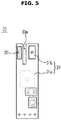
- the sensing module 30 includes one printed circuit board 33 on which the water sensing sensor 31 and the temperature sensor 32 are mounted, a sensor housing 34 accommodating the printed circuit board 33 on which the water sensing sensor 31 and the temperature sensor 32 are mounted, and a sealing member 25 which is installed to the sensor housing 34 to prevent leakage of water from between the sensor housing 34 and a seating portion 15e, to be described later, together with the above-mentioned water sensing sensor 31 and the temperature sensor 32.
- the printed circuit board 33 By accommodating the printed circuit board 33 in a space within the sensor housing 34 and then injecting and condensing a molten resin, the printed circuit board 33 is fixed in the sensor housing 34 while a space between an inner surface of the sensor housing 34 and the printed circuit board 33 is filled with the resin.
- the printed circuit board 33 may be configured of a double-sided printed circuit board on both sides of which circuit patterns are formed.
- the water sensing sensor 31 is configured of a capacitive sensor which includes a first electrode 31a disposed on a first surface of the printed circuit board 33 and a second electrode 31b disposed on a second surface of the printed circuit board 33 opposite to the first surface.
- Each of the first and second electrodes 31a and 31b maybe formed in a metal plate shape, the first electrode 31a may be disposed at a central side on the first surface of the printed circuit board 33, and the second electrode 31b and the temperature sensor 32 may be disposed side by side at one end side on the second surface of the printed circuit board 33.
- the other end side of the printed circuit board 33 may be provided with connection portions 33b, and wires for signal transmission and power supply are connected to the connection portions 33b.
- the printed circuit board 33 may be provided with a slit 33a partitioning between the second electrode 31b and the temperature sensor 32, it maybe possible to prevent operations of the second electrode 31b and the temperature sensor 32 from interfering with each other.
- the above-mentioned capacitive sensor is a sensor to sense a change in capacitance depending on a change in dielectric constant between the two electrodes spaced apart from each other.
- the sensing sensor 31 configured of a capacitive sensor is incorporated into the sensing module 30 and then the sensing module 30 is installed to the water collecting portion 15a, a dielectric substance between the first electrode 31a and the second electrode 31b is changed depending on a level of water filled in the water collecting portion 15a, and thus capacitance between the first electrode 31a and the second electrode 31b is changed. Accordingly, it may be possible to identify whether or not water is filled to a certain water level or more in the water collecting portion 15a through such a change in capacitance.
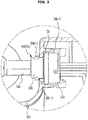
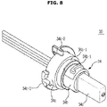
- the water collecting portion 15a is provided with a through hole 15c arranged to install the sensing module 30, and a seating portion 15e extending from a part adjacent to the through hole 15c to the outside so as to seat a mounting portion 34c of the sensor housing 34, to be described later.
- the part adjacent to the through hole 15c is formed with a catching jaw 15d protruding inward of the seating portion 15e to catch and support the mounting portion 34c.
- the sensor housing 34 may integrally include a sensing portion 34a which protrudes inward of the water collecting portion through the through hole 15c to come into contact with water filled in the water collecting portion 15e, a through portion 34b which may be formed to have a circular cross-section and rests on an inner surface of the through hole 15c, and a mounting portion 34c seated to the above-mentioned seating portion 15e to maintain a state in which the sensing module 30 is installed to the water collecting portion 15a.
- the sensing portion 34a accommodates therein one end of the printed circuit board 33 on which the water sensing sensor 31 and the temperature sensor 32 are mounted, and thus senses whether or not water is present and the temperature of water.
- the through portion 34b may include a catching portion 34b-1 protruding from an outer peripheral surface thereof.
- the catching portion 34b-1 passes through the through hole 15c, and then rests on a part adjacent to the through hole 15c of the water collecting portion 15a depending on rotation of the sensing module 30, thereby maintaining a state in which the through portion 34b is installed to the through hole 15c.
- the catching portion 34b-1 includes two catching portions 34b-1 which are spaced apart from each other in a circumferential direction, and the two catching portions 34b-1 are formed to have different lengths from each other in the circumferential direction.
- the through hole 15c provided in the water collecting portion 15a includes a sensing portion passing part 15c-1 through which the sensing portion 34a passes, and catching portion passing parts 15c-2 arranged in shapes corresponding to the catching portions 34b-1 at both sides of the sensing portion passing part 15c-1. Accordingly, the two catching portions 34b-1 may pass through the two catching portion passing parts 15c-2 only when the sensing module 30 is installed to the through hole 15c at a certain angle.
- the mounting portion 34c is formed to have a larger diameter than the through hole 15c so as to be caught and supported by the above-mentioned catching jaw 15d, and includes a sealing member installation portion 34c-1 to which the sealing member 25 is installed.
- the seating portion 15e is provided with stopper portions 15e-1 protruding to limit a rotation angle of the sensing module 30 rotating as described above, and the mounting portion 34c is provided with stopper protrusions 34c-2 corresponding to the stopper portions 15e-1. Consequently, when the sensing module 30 rotates, the two stopper protrusions 34c-2 are caught by the two stopper portions 15e-1 such that the rotation angle of the sensing module 30 is limited to a certain degree or less.
- the two stopper portions 15e-1 are formed at the seating portion 15e to be spaced in the circumferential direction
- the two stopper protrusions 34c-2 are formed at the mounting portion 34c to be spaced in the circumferential direction such that the two stopper protrusions 34c-2 correspond to the two stopper portions 15e-1.
- the seating portion 15e is formed, at a fore end thereof, with a locking portion 15e-2 protruding in order for the sensing module 30 rotating in one direction to limit rotation in a reverse direction.
- the mounting portion 34c of the sensor housing 34 is provided with an elastic hook 34c-3 arranged to correspond to the locking portion 15e-2, and the elastic hook 34c-3 is elastically deformed depending on the rotation of the sensing module 30 and is caught by the locking portion 15e-2.
- the sealing member 25 is formed of an O-ring made of an elastically deformable material, and is installed to the above-mentioned sealing member installation portion 34c-1. Accordingly, when the sensing module 30 is installed to the water collecting portion 15a and the mounting portion 34c is inserted into the seating portion 15e after the sealing member 25 is installed to the sealing member installation portion 34c-1 of the mounting portion 34c, a gap between the outer peripheral surface of the mounting portion 34c and the inner peripheral surface of the seating portion 15e is sealed by the sealing member 25. Therefore, leakage of water from the through hole 15c is prevented.
- a process of installing the sensing module 30 having the above-mentioned structure to the water collecting portion 15a is as follows.
- the sensing module 30 when the sensing module 30 is inserted into the through hole 15c at a certain angle such that the two catching portions 34b-1 may pass through the two catching passing parts 15c-2, the two catching portions 34b-1 pass through the two corresponding catching passing parts 15c-2, respectively, and the mounting portion 34c enters inside the seating portion 15e to be caught by the catching jaw 15d, as shown in FIG. 9 .
- the sensing module 30 rotates in one direction, the elastic hook 34c-3 is temporarily elastically deformed and is then returned to an original position to be thereby caught by the locking portion 15e-1. Therefore, the sensing module 30 is prevented from rotating in a reverse direction until a certain force or more is applied to the sensing module 30.
- the two catching portions 34b-1 and the two catching portion passing parts 15c-2 are formed to have different lengths from each other in the circumferential direction, but the present disclosure is not limited thereto.
- the two catching portions 34b-1 may be formed to have different shapes from each other, and the two catching portion passing parts 15c-2 maybe formed to have respective shapes corresponding to the two catching portions 34b-1, whereby the sensing module 30 may also be installed to the water collecting portion 15a at a certain angle.
- the water sensing sensor 31 incorporated into the sensing module 30 senses whether or not water is present around the sensing module 30.
- the circulation pump 18 is operated. Water gathered in the water collecting portion 15a according to the operation of the circulation pump 18 is transferred to the nozzle units 14L, 14U, and 14M, and water transferred to the nozzle units 14L, 14U, and 14M is sprayed onto the dished put on the racks 13U and 13L through the nozzles to wash contaminants off of the dishes.
- the operation of the circulation pump 18 is stopped after the dishwashing is completed, and the drain pump 19 is operated to discharge water gathered in the water collecting portion 15 through the drain tube 21 to the outside.
- the water sensing sensor 31 incorporated into the sensing module 30 senses whether or not water is present around the sensing module 30.
- the operation of the circulation pump 19 is stopped and the dishwashing is completed.
- the sensing module 30 having the above-mentioned configuration is disposed to be spaced apart from the bottom of the sump 15 by a certain distance. Accordingly, water is sensed by the water sensing sensor 31 arranged in the sensing module 30 only in a state in which the water is filled to a certain water level or more within the sump 15. This serves to prevent the following issue. Water in the sump 15 is difficult to be perfectly discharged under the structure of the dishwasher, and thus residual water may be unavoidably present in the lower portion of the sump 15. Therefore, it may be misidentified that water is filled in the sump when the above residual water is sensed by the sensing module 30. Accordingly, such an issue is prevented by the above-mentioned structure.
- the water sensing sensor 31 is configured of a capacitive sensor in this embodiment, the present disclosure is not limited thereto.
- the sensing module 30 may employ any other type of proximity sensor together with the temperature sensor 32 so as to be operated as the water sensing sensor 31 and the temperature sensor 32.
- the present disclosure is not limited thereto.
- the sensing module 30 may have a more compact size by arranging the first electrode 31a and the second electrode 31b at both sides of the printed circuit board 33.
- a water sensing sensor may be realized by a capacitive sensor having a first electrode and a second electrode arranged on both sides of a printed circuit board in a sensing module applied to a dishwasher, the size of the water sensing sensor may be reduced and thus the sensing module may have a compact size.
- one sensing module is installed to a sump and may sense whether or not water is present and the temperature of water, so that an inner space of the sump may be efficiently utilized.
Landscapes
- Engineering & Computer Science (AREA)
- Water Supply & Treatment (AREA)
- Physics & Mathematics (AREA)
- General Physics & Mathematics (AREA)
- Washing And Drying Of Tableware (AREA)
Claims (14)
- Geschirrspülmaschine, die Folgendes aufweist:eine Spülkammer (11a) zum Durchführen von Geschirrspülen;einen Wassersammelteil (15a), der an einem unteren Teil der Spülkammer bereitgestellt ist, zum Sammeln von zum Spülen verwendetem Wasser; undein Sensormodul (30), das im Wassersammelteil angeordnet ist und integral einen Wassererfassungssensor (31) zum Erfassen, ob Wasser vorhanden ist oder nicht, und einen Temperatursensor (32) zum Erfassen einer Wassertemperatur aufweist, wobei der Wassererfassungssensor einen kapazitiven Sensor umfasst.
- Geschirrspülmaschine nach Anspruch 1, wobei das Erfassungsmodul (30) so angeordnet ist, dass es von einem Boden des Wassersammelteils (15a) beabstandet ist.
- Geschirrspülmaschine nach Anspruch 1 oder 2, wobei:das Erfassungsmodul (30) eine Platine (33) aufweist, auf der der Wassererfassungssensor (31) und der Temperatursensor (32) montiert sind; undder kapazitive Sensor eine erste Elektrode (31a), die auf einer ersten Oberfläche der Platine angeordnet ist, und eine zweite Elektrode (31b), die auf einer der ersten Oberfläche entgegengesetzten zweiten Oberfläche der Platine angeordnet ist, aufweist.
- Geschirrspülmaschine nach Anspruch 3, wobei die zweite Elektrode (31b) und der Temperatursensor (32) Seite an Seite an einem Ende der Platine (33) angeordnet sind.
- Geschirrspülmaschine nach Anspruch 4, wobei die Platine (33) einen Schlitz (33a) aufweist, der zwischen der zweiten Elektrode (31b) und dem Temperatursensor (32) bereitgestellt ist.
- Geschirrspülmaschine nach einem der Ansprüche 3 bis 5, wobei das Erfassungsmodul (30) ein Sensorgehäuse (34) aufweist, das die Platine (33) aufnimmt, auf der der Wassererfassungssensor (31) und der Temperatursensor (32) montiert sind.
- Geschirrspülmaschine nach Anspruch 6, wobei das Erfassungsmodul (30) ferner ein Kunstharz aufweist, das in einen Innenteil des Sensorgehäuses (34) eingefüllt ist, um einen Zwischenraum zwischen der Platine (33) und dem Innenteil des Sensorgehäuses zu füllen.
- Geschirrspülmaschine nach Anspruch 6 oder 7, wobei:das Sensorgehäuse (34) einen Erfassungsteil (34a) aufweist, der einwärts des Wassersammelteils (15a) vorsteht, wobei die Platine (33) innerhalb des Erfassungsteils angeordnet ist; undder Wassersammelteil (15a) eine Durchgangsbohrung (15c) aufweist, die an einer Seitenwand davon bereitgestellt ist, wobei das Erfassungsteil durch die Durchgangsbohrung vorsteht.
- Geschirrspülmaschine nach Anspruch 8, wobei:das Sensorgehäuse (34) wenigstens einen Rastteil (34b-1) aufweist, der von einer äußeren Umfangsfläche davon vorsteht; unddie Durchgangsbohrung (15c) einen Erfassungsteildurchgangsbereich (15c-1), durch den hindurch der Erfassungsteil (34a) verläuft, und wenigstens einen Rastteildurchgangsbereich (15c-2), der in einer Form ausgebildet ist, die dem wenigstens einen Rastteil entspricht, so dass der wenigstens eine Rastteil durch den wenigstens einen Rastteildurchgangsbereich verläuft, aufweist.
- Geschirrspülmaschine nach Anspruch 9, wobei:der wenigstens eine Rastteil (34b-1) zwei Rastteile aufweist, die in voneinander verschiedenen Formen ausgebildet sind; undder wenigstens eine Rastteildurchgangsbereich (15c-2) zwei Rastteildurchgangsbereiche aufweist, die in jeweiligen Formen entsprechend den zwei Rastteilen ausgebildet sind.
- Geschirrspülmaschine nach Anspruch 8, 9 oder 10, wobei:das Sensorgehäuse (34) einen Montageteil (34c) aufweist, der so ausgebildet ist, dass er einen größeren Durchmesser als die Durchgangsbohrung (15c) hat; undder Wassersammelteil (15a) einen Sitzteil (15e) aufweist, der sich von einem an die Durchgangsbohrung angrenzenden Bereich zum Aufsetzen und Tragen des Montageteils erstreckt.
- Geschirrspülmaschine nach Anspruch 11, die ferner ein Dichtungselement (25) zum Abdichten zwischen einer inneren Umfangsfläche des Sitzteils (15e) und einer äußeren Umfangsfläche des Montageteils (34c) aufweist.
- Geschirrspülmaschine nach Anspruch 9, wobei:der Wassersammelteil (15a) ein Paar Anschlagteile (15e-1) zum Beschränken eines Drehungswinkels des Erfassungsmoduls (30) aufweist; unddas Sensorgehäuse (34) ein Paar Anschlagvorsprünge (34c-2) aufweist, die je nach der Drehung des Erfassungsmoduls jeweilig an dem Paar Anschlagteile verrastet werden.
- Geschirrspülmaschine nach Anspruch 9, wobei:der Wassersammelteil (15a) einen Sperrteil (15e-2) aufweist, der vorsteht, damit das sich in einer Richtung drehende Erfassungsmodul (30) die Drehung in einer Rückwärtsrichtung beschränkt; unddas Sensorgehäuse (34) einen elastischen Haken (34c-2) aufweist, der bereitgestellt ist, um dem Sperrteil zu entsprechen, wobei der elastische Haken bei Drehung des Erfassungsmoduls in einer Richtung und bei Verrasten an dem Sperrteil elastisch verformt wird.
Applications Claiming Priority (1)
| Application Number | Priority Date | Filing Date | Title |
|---|---|---|---|
| KR1020130046132A KR101981679B1 (ko) | 2013-04-25 | 2013-04-25 | 식기세척기 및 식기세척기의 센싱 모듈 |
Publications (3)
| Publication Number | Publication Date |
|---|---|
| EP2796080A2 EP2796080A2 (de) | 2014-10-29 |
| EP2796080A3 EP2796080A3 (de) | 2015-03-11 |
| EP2796080B1 true EP2796080B1 (de) | 2021-06-16 |
Family
ID=50542921
Family Applications (1)
| Application Number | Title | Priority Date | Filing Date |
|---|---|---|---|
| EP14165840.1A Active EP2796080B1 (de) | 2013-04-25 | 2014-04-24 | Geschirrspülmaschine und Messmodul dafür |
Country Status (3)
| Country | Link |
|---|---|
| US (1) | US9861255B2 (de) |
| EP (1) | EP2796080B1 (de) |
| KR (1) | KR101981679B1 (de) |
Families Citing this family (11)
| Publication number | Priority date | Publication date | Assignee | Title |
|---|---|---|---|---|
| GB201300362D0 (en) * | 2013-01-09 | 2013-02-20 | Reckitt Benckiser Uk Ltd | Low cost senor system |
| US10335008B1 (en) * | 2013-12-05 | 2019-07-02 | Chris Gilreath | Water conserving cleaning system, apparatus and method |
| US9782053B2 (en) * | 2013-12-05 | 2017-10-10 | Christopher J. Gilreath | Water conserving cleaning system, apparatus, and method |
| US10722095B1 (en) * | 2013-12-05 | 2020-07-28 | Chris Gilreath | Water conserving cleaning system, apparatus and method |
| KR101717936B1 (ko) * | 2015-04-22 | 2017-03-21 | 주식회사 경신 | 차량용 배터리팩모듈의 온도측정 장치 |
| CN104905746B (zh) * | 2015-06-26 | 2018-03-30 | 佛山市顺德区美的洗涤电器制造有限公司 | 洗碗机 |
| US10335012B2 (en) | 2015-10-19 | 2019-07-02 | Electrolux Home Products, Inc. | Dishwasher spray fill |
| KR101700275B1 (ko) | 2015-11-27 | 2017-01-31 | 린나이코리아 주식회사 | 식기세척기의 센싱 모듈 |
| US9993132B2 (en) * | 2015-12-16 | 2018-06-12 | Whirlpool Corporation | Dish treating appliance with leak detection |
| CN108534914B (zh) * | 2018-04-18 | 2023-09-22 | 北京方等传感器研究所有限公司 | 温度传感器连接结构及连接系统 |
| CN108968861A (zh) * | 2018-08-31 | 2018-12-11 | 杭州川月科技有限公司 | 一种洗碗机的洗碗方法及洗碗机 |
Family Cites Families (6)
| Publication number | Priority date | Publication date | Assignee | Title |
|---|---|---|---|---|
| US5446531A (en) * | 1994-05-20 | 1995-08-29 | Honeywell Inc. | Sensor platform for use in machines for washing articles |
| DE50210345D1 (de) | 2002-01-31 | 2007-08-02 | Emz Hanauer Gmbh & Co Kgaa | Trübungssensor mit Temperaturerfassung für Haushaltsgeräte |
| US7028697B2 (en) | 2002-05-03 | 2006-04-18 | Whirlpool Corporation | In-sink dishwasher |
| EP1677085A3 (de) | 2004-12-31 | 2007-08-01 | Moonhaven LLC | Kapazitiver Niveau-Sensor |
| US20060237036A1 (en) * | 2005-04-25 | 2006-10-26 | Viking Range Corporation | Fill level control system for an article cleaning apparatus |
| EP2233058B1 (de) | 2009-03-27 | 2013-05-08 | Electrolux Home Products Corporation N.V. | Geschirrspüler |
-
2013
- 2013-04-25 KR KR1020130046132A patent/KR101981679B1/ko not_active Expired - Fee Related
-
2014
- 2014-04-22 US US14/258,628 patent/US9861255B2/en active Active
- 2014-04-24 EP EP14165840.1A patent/EP2796080B1/de active Active
Non-Patent Citations (1)
| Title |
|---|
| None * |
Also Published As
| Publication number | Publication date |
|---|---|
| EP2796080A2 (de) | 2014-10-29 |
| EP2796080A3 (de) | 2015-03-11 |
| KR101981679B1 (ko) | 2019-05-23 |
| US20140318585A1 (en) | 2014-10-30 |
| US9861255B2 (en) | 2018-01-09 |
| KR20140127594A (ko) | 2014-11-04 |
Similar Documents
| Publication | Publication Date | Title |
|---|---|---|
| EP2796080B1 (de) | Geschirrspülmaschine und Messmodul dafür | |
| US20180214002A1 (en) | Metering device for the metered addition of detergents | |
| RU2530374C2 (ru) | Предохранительное устройство для посудомоечной машины | |
| JP4149807B2 (ja) | 洗浄プロセスを監視する装置 | |
| US10358763B2 (en) | Laundry washing machine with improved level sensing device | |
| EP3476269B1 (de) | Verfahren zur automatischen beurteilung des in einer geschirrspülmaschine verwendeten spülmitteltyps | |
| US9999340B2 (en) | Dishwasher and dispensing assembly | |
| US9378630B2 (en) | Method for preventing input on an apparatus having a user interface | |
| US12252834B2 (en) | Detergent storage container and method for manufacturing the same | |
| US20120249467A1 (en) | Appliance having a touch user interface with a curved surface | |
| US11344176B2 (en) | Dishwasher appliances and methods for determining wash additive levels | |
| KR20200142506A (ko) | 사용자 감지 기능을 갖는 세탁 기기 | |
| US20100170541A1 (en) | Safety arrangement for a dishwasher, and associated apparatus | |
| US20150245760A1 (en) | Dishwasher appliance and vent for same | |
| EP2767631A1 (de) | Waschmaschine mit verbesserter Füllstandsmessvorrichtung | |
| KR101366287B1 (ko) | 식기 수납체 및 이를 이용한 식기 세척기 | |
| KR102352392B1 (ko) | 식기세척기 | |
| US20140130831A1 (en) | Method and device for detecting a water change in a water-bearing household appliance, in particular a dishwasher | |
| EP3179896B1 (de) | Geschirrspüler | |
| EP3197332B1 (de) | Geschirrspüler | |
| EP2887856B1 (de) | Chemischer sensor für eine geschirrspülmaschine und zugehöriges system und verfahren | |
| KR20070112720A (ko) | 식기 세척기 | |
| KR102161561B1 (ko) | 식기세척기 | |
| EP3928676B1 (de) | Geschirrspüler | |
| EP3738496B1 (de) | Geschirrkorberkennungssystem für kindersicherheit und verfahren zur steuerung einer geschirrspülmaschine |
Legal Events
| Date | Code | Title | Description |
|---|---|---|---|
| PUAI | Public reference made under article 153(3) epc to a published international application that has entered the european phase |
Free format text: ORIGINAL CODE: 0009012 |
|
| 17P | Request for examination filed |
Effective date: 20140424 |
|
| AK | Designated contracting states |
Kind code of ref document: A2 Designated state(s): AL AT BE BG CH CY CZ DE DK EE ES FI FR GB GR HR HU IE IS IT LI LT LU LV MC MK MT NL NO PL PT RO RS SE SI SK SM TR |
|
| AX | Request for extension of the european patent |
Extension state: BA ME |
|
| PUAL | Search report despatched |
Free format text: ORIGINAL CODE: 0009013 |
|
| AK | Designated contracting states |
Kind code of ref document: A3 Designated state(s): AL AT BE BG CH CY CZ DE DK EE ES FI FR GB GR HR HU IE IS IT LI LT LU LV MC MK MT NL NO PL PT RO RS SE SI SK SM TR |
|
| AX | Request for extension of the european patent |
Extension state: BA ME |
|
| RIC1 | Information provided on ipc code assigned before grant |
Ipc: A47L 15/42 20060101AFI20150205BHEP |
|
| R17P | Request for examination filed (corrected) |
Effective date: 20150911 |
|
| RBV | Designated contracting states (corrected) |
Designated state(s): AL AT BE BG CH CY CZ DE DK EE ES FI FR GB GR HR HU IE IS IT LI LT LU LV MC MK MT NL NO PL PT RO RS SE SI SK SM TR |
|
| STAA | Information on the status of an ep patent application or granted ep patent |
Free format text: STATUS: EXAMINATION IS IN PROGRESS |
|
| 17Q | First examination report despatched |
Effective date: 20200730 |
|
| GRAP | Despatch of communication of intention to grant a patent |
Free format text: ORIGINAL CODE: EPIDOSNIGR1 |
|
| STAA | Information on the status of an ep patent application or granted ep patent |
Free format text: STATUS: GRANT OF PATENT IS INTENDED |
|
| INTG | Intention to grant announced |
Effective date: 20210121 |
|
| GRAS | Grant fee paid |
Free format text: ORIGINAL CODE: EPIDOSNIGR3 |
|
| GRAA | (expected) grant |
Free format text: ORIGINAL CODE: 0009210 |
|
| STAA | Information on the status of an ep patent application or granted ep patent |
Free format text: STATUS: THE PATENT HAS BEEN GRANTED |
|
| AK | Designated contracting states |
Kind code of ref document: B1 Designated state(s): AL AT BE BG CH CY CZ DE DK EE ES FI FR GB GR HR HU IE IS IT LI LT LU LV MC MK MT NL NO PL PT RO RS SE SI SK SM TR |
|
| RAP3 | Party data changed (applicant data changed or rights of an application transferred) |
Owner name: SAMSUNG ELECTRONICS CO., LTD. |
|
| REG | Reference to a national code |
Ref country code: GB Ref legal event code: FG4D |
|
| REG | Reference to a national code |
Ref country code: CH Ref legal event code: EP |
|
| REG | Reference to a national code |
Ref country code: DE Ref legal event code: R096 Ref document number: 602014078109 Country of ref document: DE |
|
| REG | Reference to a national code |
Ref country code: AT Ref legal event code: REF Ref document number: 1401612 Country of ref document: AT Kind code of ref document: T Effective date: 20210715 |
|
| REG | Reference to a national code |
Ref country code: IE Ref legal event code: FG4D |
|
| REG | Reference to a national code |
Ref country code: LT Ref legal event code: MG9D |
|
| PG25 | Lapsed in a contracting state [announced via postgrant information from national office to epo] |
Ref country code: FI Free format text: LAPSE BECAUSE OF FAILURE TO SUBMIT A TRANSLATION OF THE DESCRIPTION OR TO PAY THE FEE WITHIN THE PRESCRIBED TIME-LIMIT Effective date: 20210616 Ref country code: LT Free format text: LAPSE BECAUSE OF FAILURE TO SUBMIT A TRANSLATION OF THE DESCRIPTION OR TO PAY THE FEE WITHIN THE PRESCRIBED TIME-LIMIT Effective date: 20210616 Ref country code: BG Free format text: LAPSE BECAUSE OF FAILURE TO SUBMIT A TRANSLATION OF THE DESCRIPTION OR TO PAY THE FEE WITHIN THE PRESCRIBED TIME-LIMIT Effective date: 20210916 Ref country code: HR Free format text: LAPSE BECAUSE OF FAILURE TO SUBMIT A TRANSLATION OF THE DESCRIPTION OR TO PAY THE FEE WITHIN THE PRESCRIBED TIME-LIMIT Effective date: 20210616 |
|
| REG | Reference to a national code |
Ref country code: AT Ref legal event code: MK05 Ref document number: 1401612 Country of ref document: AT Kind code of ref document: T Effective date: 20210616 |
|
| REG | Reference to a national code |
Ref country code: NL Ref legal event code: MP Effective date: 20210616 |
|
| PG25 | Lapsed in a contracting state [announced via postgrant information from national office to epo] |
Ref country code: NO Free format text: LAPSE BECAUSE OF FAILURE TO SUBMIT A TRANSLATION OF THE DESCRIPTION OR TO PAY THE FEE WITHIN THE PRESCRIBED TIME-LIMIT Effective date: 20210916 Ref country code: SE Free format text: LAPSE BECAUSE OF FAILURE TO SUBMIT A TRANSLATION OF THE DESCRIPTION OR TO PAY THE FEE WITHIN THE PRESCRIBED TIME-LIMIT Effective date: 20210616 Ref country code: RS Free format text: LAPSE BECAUSE OF FAILURE TO SUBMIT A TRANSLATION OF THE DESCRIPTION OR TO PAY THE FEE WITHIN THE PRESCRIBED TIME-LIMIT Effective date: 20210616 Ref country code: LV Free format text: LAPSE BECAUSE OF FAILURE TO SUBMIT A TRANSLATION OF THE DESCRIPTION OR TO PAY THE FEE WITHIN THE PRESCRIBED TIME-LIMIT Effective date: 20210616 Ref country code: GR Free format text: LAPSE BECAUSE OF FAILURE TO SUBMIT A TRANSLATION OF THE DESCRIPTION OR TO PAY THE FEE WITHIN THE PRESCRIBED TIME-LIMIT Effective date: 20210917 |
|
| PG25 | Lapsed in a contracting state [announced via postgrant information from national office to epo] |
Ref country code: SM Free format text: LAPSE BECAUSE OF FAILURE TO SUBMIT A TRANSLATION OF THE DESCRIPTION OR TO PAY THE FEE WITHIN THE PRESCRIBED TIME-LIMIT Effective date: 20210616 Ref country code: SK Free format text: LAPSE BECAUSE OF FAILURE TO SUBMIT A TRANSLATION OF THE DESCRIPTION OR TO PAY THE FEE WITHIN THE PRESCRIBED TIME-LIMIT Effective date: 20210616 Ref country code: EE Free format text: LAPSE BECAUSE OF FAILURE TO SUBMIT A TRANSLATION OF THE DESCRIPTION OR TO PAY THE FEE WITHIN THE PRESCRIBED TIME-LIMIT Effective date: 20210616 Ref country code: CZ Free format text: LAPSE BECAUSE OF FAILURE TO SUBMIT A TRANSLATION OF THE DESCRIPTION OR TO PAY THE FEE WITHIN THE PRESCRIBED TIME-LIMIT Effective date: 20210616 Ref country code: PT Free format text: LAPSE BECAUSE OF FAILURE TO SUBMIT A TRANSLATION OF THE DESCRIPTION OR TO PAY THE FEE WITHIN THE PRESCRIBED TIME-LIMIT Effective date: 20211018 Ref country code: NL Free format text: LAPSE BECAUSE OF FAILURE TO SUBMIT A TRANSLATION OF THE DESCRIPTION OR TO PAY THE FEE WITHIN THE PRESCRIBED TIME-LIMIT Effective date: 20210616 Ref country code: RO Free format text: LAPSE BECAUSE OF FAILURE TO SUBMIT A TRANSLATION OF THE DESCRIPTION OR TO PAY THE FEE WITHIN THE PRESCRIBED TIME-LIMIT Effective date: 20210616 Ref country code: ES Free format text: LAPSE BECAUSE OF FAILURE TO SUBMIT A TRANSLATION OF THE DESCRIPTION OR TO PAY THE FEE WITHIN THE PRESCRIBED TIME-LIMIT Effective date: 20210616 Ref country code: AT Free format text: LAPSE BECAUSE OF FAILURE TO SUBMIT A TRANSLATION OF THE DESCRIPTION OR TO PAY THE FEE WITHIN THE PRESCRIBED TIME-LIMIT Effective date: 20210616 |
|
| PG25 | Lapsed in a contracting state [announced via postgrant information from national office to epo] |
Ref country code: PL Free format text: LAPSE BECAUSE OF FAILURE TO SUBMIT A TRANSLATION OF THE DESCRIPTION OR TO PAY THE FEE WITHIN THE PRESCRIBED TIME-LIMIT Effective date: 20210616 |
|
| REG | Reference to a national code |
Ref country code: DE Ref legal event code: R097 Ref document number: 602014078109 Country of ref document: DE |
|
| PLBE | No opposition filed within time limit |
Free format text: ORIGINAL CODE: 0009261 |
|
| STAA | Information on the status of an ep patent application or granted ep patent |
Free format text: STATUS: NO OPPOSITION FILED WITHIN TIME LIMIT |
|
| PG25 | Lapsed in a contracting state [announced via postgrant information from national office to epo] |
Ref country code: DK Free format text: LAPSE BECAUSE OF FAILURE TO SUBMIT A TRANSLATION OF THE DESCRIPTION OR TO PAY THE FEE WITHIN THE PRESCRIBED TIME-LIMIT Effective date: 20210616 |
|
| PGFP | Annual fee paid to national office [announced via postgrant information from national office to epo] |
Ref country code: GB Payment date: 20220321 Year of fee payment: 9 |
|
| 26N | No opposition filed |
Effective date: 20220317 |
|
| PG25 | Lapsed in a contracting state [announced via postgrant information from national office to epo] |
Ref country code: AL Free format text: LAPSE BECAUSE OF FAILURE TO SUBMIT A TRANSLATION OF THE DESCRIPTION OR TO PAY THE FEE WITHIN THE PRESCRIBED TIME-LIMIT Effective date: 20210616 |
|
| PG25 | Lapsed in a contracting state [announced via postgrant information from national office to epo] |
Ref country code: IT Free format text: LAPSE BECAUSE OF FAILURE TO SUBMIT A TRANSLATION OF THE DESCRIPTION OR TO PAY THE FEE WITHIN THE PRESCRIBED TIME-LIMIT Effective date: 20210616 |
|
| PGFP | Annual fee paid to national office [announced via postgrant information from national office to epo] |
Ref country code: DE Payment date: 20220321 Year of fee payment: 9 |
|
| REG | Reference to a national code |
Ref country code: CH Ref legal event code: PL |
|
| REG | Reference to a national code |
Ref country code: BE Ref legal event code: MM Effective date: 20220430 |
|
| PG25 | Lapsed in a contracting state [announced via postgrant information from national office to epo] |
Ref country code: MC Free format text: LAPSE BECAUSE OF FAILURE TO SUBMIT A TRANSLATION OF THE DESCRIPTION OR TO PAY THE FEE WITHIN THE PRESCRIBED TIME-LIMIT Effective date: 20210616 Ref country code: LU Free format text: LAPSE BECAUSE OF NON-PAYMENT OF DUE FEES Effective date: 20220424 Ref country code: LI Free format text: LAPSE BECAUSE OF NON-PAYMENT OF DUE FEES Effective date: 20220430 Ref country code: FR Free format text: LAPSE BECAUSE OF NON-PAYMENT OF DUE FEES Effective date: 20220430 Ref country code: CH Free format text: LAPSE BECAUSE OF NON-PAYMENT OF DUE FEES Effective date: 20220430 |
|
| PG25 | Lapsed in a contracting state [announced via postgrant information from national office to epo] |
Ref country code: BE Free format text: LAPSE BECAUSE OF NON-PAYMENT OF DUE FEES Effective date: 20220430 |
|
| PG25 | Lapsed in a contracting state [announced via postgrant information from national office to epo] |
Ref country code: IE Free format text: LAPSE BECAUSE OF NON-PAYMENT OF DUE FEES Effective date: 20220424 |
|
| REG | Reference to a national code |
Ref country code: DE Ref legal event code: R119 Ref document number: 602014078109 Country of ref document: DE |
|
| GBPC | Gb: european patent ceased through non-payment of renewal fee |
Effective date: 20230424 |
|
| PG25 | Lapsed in a contracting state [announced via postgrant information from national office to epo] |
Ref country code: GB Free format text: LAPSE BECAUSE OF NON-PAYMENT OF DUE FEES Effective date: 20230424 |
|
| PG25 | Lapsed in a contracting state [announced via postgrant information from national office to epo] |
Ref country code: GB Free format text: LAPSE BECAUSE OF NON-PAYMENT OF DUE FEES Effective date: 20230424 Ref country code: DE Free format text: LAPSE BECAUSE OF NON-PAYMENT OF DUE FEES Effective date: 20231103 |
|
| PG25 | Lapsed in a contracting state [announced via postgrant information from national office to epo] |
Ref country code: HU Free format text: LAPSE BECAUSE OF FAILURE TO SUBMIT A TRANSLATION OF THE DESCRIPTION OR TO PAY THE FEE WITHIN THE PRESCRIBED TIME-LIMIT; INVALID AB INITIO Effective date: 20140424 |
|
| PG25 | Lapsed in a contracting state [announced via postgrant information from national office to epo] |
Ref country code: MK Free format text: LAPSE BECAUSE OF FAILURE TO SUBMIT A TRANSLATION OF THE DESCRIPTION OR TO PAY THE FEE WITHIN THE PRESCRIBED TIME-LIMIT Effective date: 20210616 Ref country code: CY Free format text: LAPSE BECAUSE OF FAILURE TO SUBMIT A TRANSLATION OF THE DESCRIPTION OR TO PAY THE FEE WITHIN THE PRESCRIBED TIME-LIMIT Effective date: 20210616 |
|
| PG25 | Lapsed in a contracting state [announced via postgrant information from national office to epo] |
Ref country code: TR Free format text: LAPSE BECAUSE OF FAILURE TO SUBMIT A TRANSLATION OF THE DESCRIPTION OR TO PAY THE FEE WITHIN THE PRESCRIBED TIME-LIMIT Effective date: 20210616 |
|
| PG25 | Lapsed in a contracting state [announced via postgrant information from national office to epo] |
Ref country code: MT Free format text: LAPSE BECAUSE OF FAILURE TO SUBMIT A TRANSLATION OF THE DESCRIPTION OR TO PAY THE FEE WITHIN THE PRESCRIBED TIME-LIMIT Effective date: 20210616 |