EP2796178A1 - Entspannungsflotationsvorrichtung zum Klären von Flüssigkeit - Google Patents
Entspannungsflotationsvorrichtung zum Klären von Flüssigkeit Download PDFInfo
- Publication number
- EP2796178A1 EP2796178A1 EP20140165628 EP14165628A EP2796178A1 EP 2796178 A1 EP2796178 A1 EP 2796178A1 EP 20140165628 EP20140165628 EP 20140165628 EP 14165628 A EP14165628 A EP 14165628A EP 2796178 A1 EP2796178 A1 EP 2796178A1
- Authority
- EP
- European Patent Office
- Prior art keywords
- header
- effluent
- zone
- collection
- influent
- Prior art date
- Legal status (The legal status is an assumption and is not a legal conclusion. Google has not performed a legal analysis and makes no representation as to the accuracy of the status listed.)
- Granted
Links
Images


Classifications
-
- C—CHEMISTRY; METALLURGY
- C02—TREATMENT OF WATER, WASTE WATER, SEWAGE, OR SLUDGE
- C02F—TREATMENT OF WATER, WASTE WATER, SEWAGE, OR SLUDGE
- C02F1/00—Treatment of water, waste water, or sewage
- C02F1/24—Treatment of water, waste water, or sewage by flotation
-
- B—PERFORMING OPERATIONS; TRANSPORTING
- B03—SEPARATION OF SOLID MATERIALS USING LIQUIDS OR USING PNEUMATIC TABLES OR JIGS; MAGNETIC OR ELECTROSTATIC SEPARATION OF SOLID MATERIALS FROM SOLID MATERIALS OR FLUIDS; SEPARATION BY HIGH-VOLTAGE ELECTRIC FIELDS
- B03D—FLOTATION; DIFFERENTIAL SEDIMENTATION
- B03D1/00—Flotation
- B03D1/14—Flotation machines
- B03D1/1431—Dissolved air flotation machines
-
- B—PERFORMING OPERATIONS; TRANSPORTING
- B03—SEPARATION OF SOLID MATERIALS USING LIQUIDS OR USING PNEUMATIC TABLES OR JIGS; MAGNETIC OR ELECTROSTATIC SEPARATION OF SOLID MATERIALS FROM SOLID MATERIALS OR FLUIDS; SEPARATION BY HIGH-VOLTAGE ELECTRIC FIELDS
- B03D—FLOTATION; DIFFERENTIAL SEDIMENTATION
- B03D1/00—Flotation
- B03D1/14—Flotation machines
- B03D1/1443—Feed or discharge mechanisms for flotation tanks
- B03D1/1475—Flotation tanks having means for discharging the pulp, e.g. as a bleed stream
-
- B—PERFORMING OPERATIONS; TRANSPORTING
- B03—SEPARATION OF SOLID MATERIALS USING LIQUIDS OR USING PNEUMATIC TABLES OR JIGS; MAGNETIC OR ELECTROSTATIC SEPARATION OF SOLID MATERIALS FROM SOLID MATERIALS OR FLUIDS; SEPARATION BY HIGH-VOLTAGE ELECTRIC FIELDS
- B03D—FLOTATION; DIFFERENTIAL SEDIMENTATION
- B03D1/00—Flotation
- B03D1/14—Flotation machines
- B03D1/1493—Flotation machines with means for establishing a specified flow pattern
Definitions
- This invention relates to a dissolved air flotation (DAF) device for the clarification of water or other liquids as applicable. More particularly the present invention relates to a DAF device that employs a sub-natant collection header for the withdrawal of clarified effluent.
- DAF dissolved air flotation
- FIG. 1 A typical dissolved air flotation device is illustrated in FIG. 1 .
- This system comprises of an inlet chamber, a contact zone, a separation zone, and an effluent chamber.
- the contact zone further includes a micro-bubble injection installation near the device floor.
- the micro-bubble injection installation typically consists of microbubble generating nozzles installed on a nozzle header.
- the nozzle header receives pressurized liquid saturated with air and distributes it evenly to each nozzle. As the liquid passes the nozzles, micro-bubbles are generated.
- a micro-bubble injection installation may consist of multiple nozzle headers.
- the inlet zone equalizes the incoming flow.
- the micro-bubbles injected at the bottom of the contact zone attach to the suspended particulates.
- a well designed contact zone promotes the collision of micro-bubbles with the suspended particles.
- the inclination of the inlet baffle increases the contact zone area from bottom to top. The increase in contact zone area reduces the flow velocity and therefore turbulence.
- the particles with one or more micro-bubbles attached rise to the surface as the liquid flows to the separation zone. The rise of particulates to the surface is accomplished by enhancing the buoyancy via attachment of one or more micro-bubbles.
- the liquid devoid of suspended particulates and other impurities is removed from the bottom of the separation zone.
- the depth of dissolved air flotation installations operating at high surface loading rates is known to be typically more than 4.0 m. Increased depth is known to provide process advantage in terms of clarification efficiency by altering the flow path in the separation zone. However, increased depth also results in high construction costs and maintenance costs.
- Jones '687 illustrates a flotation tank within which flotation is carried out to form a layer of sludge or float on top of the water within the tank.
- Aerated water is delivered to the bottom of the tank via a plurality of admission fittings that are disposed lengthwise along the bottom of the tank.
- a valve is associated with each admission fitting to selectively render the fitting operable or inoperable.
- Vion '149 discloses an apparatus for the clarification of liquids such as water.
- the apparatus includes a feature whereby flotation equipment is placed above an assembly for the pretreatment of the liquid. This allows a hydraulic balance to be brought to the various constitutes of the apparatus. This, in turn, allows for a small upstream load and the recycling, by simple gravity, of the floating particles collected at the surface of the flotation equipment.
- the path between the contact zone and the effluent collection zone is often too short to ensure the removal of all of the agglomerated impurities.
- the path between the contact and effluent zones can be a straight line thereby reducing the time for which the liquid containing micro-bubbles is retained in the separation zone. The result of which is the lowermost agglomerated particles receive insufficient flotation time and are thus prevented from floating to the top for removal at the sludge collection chamber.
- the DAF devices of the present disclosure seek to overcome these drawback by both increasing the pathway the agglomerated particles must travel within the separation zone - thus permitting additional time for bubble-particle agglomerates with lower flotation velocities to rise to surface and separate, and decreasing the drag at the entrance to the effluent zone.
- the result is an increase in agglomerated particles that are removed via the sludge collection chamber and a corresponding decrease in impurities found within the effluent.
- a dissolved air flotation installation capable of operating at high loading rates that does not require excessive depth to improve the clarification efficiency.
- a dissolved air flotation system that is more cost effective and the design is capable of being easily incorporated in the existing conventional installations to increase the clarification capacity.
- the present invention is aimed at fulfilling these and other needs.
- One of the advantages of the present invention is that it provides dissolved air flotation with high clarification rates.
- It is a further advantage of the invention is that it greatly minimizes and/or eliminates the passage of micro-bubbles into the effluent by enhancing the flow pattern in the reactor.
- Yet another advantage of the present invention is that it allows for high rates of clarification without unnecessarily increasing the depth of the water within the device.
- Still yet another advantage is realized by utilizing a header fitted with collection channels to remove the effluent, thereby distributing the intake area over a larger region and thus reducing the drag resulting from fluid flow and therefore the amount of agglomerated particles and bubbles that are introduced into the effluent.
- Another advantage is realized by providing a dissolved air flotation system that can be inexpensively installed and maintained and that can be retrofitted into existing water treatment facilities.
- a DAF device comprising: an influent zone for receiving a volume of influent; a contact zone in communication with the influent zone. Bubbles are present or introduced within the contact zone. Thus, the bubbles contact and agglomerate with the impurities in the influent to form agglomerated particles.
- a separation zone is in communication with the contact zone, wherein the agglomerated particles being removed within the separation zone to form a clarified effluent.
- a header is provided for collecting the clarified effluent in the separation zone.
- the header may be located at an lower extent of the separation zone.
- the header comprises of a series of collection channels.
- the collection channels may have a series of apertures, preferably arranged along a lower extent of the channel.
- the collection channels are provided to collect effluent and deliver the effluent into the header.
- the apertures may be located an angle to the vertical and/or they may vary in size along the length of the collection channel.
- the header may comprises a series of discharge channels for delivering the effluent from the header to the effluent zone.
- the diameter of the discharge channels is greater than the diameter of the collection channels.
- the DAF may include a collection chamber positioned adjacent to an upper extent of separation zone.
- an effluent zone is in fluid communication with the header and /or discharge channels.
- the header has opposed ends, which are opened ends, wherein effluent zones are connected to the opposed, opened ends of the header.
- the collection and discharge channels are arranged perpendicular to the header.
- the total volumetric intake of the collection channels is equal to the total volumetric output of the discharge channels.
- the discharge channel is not in the same plane or level as the collection channels or the header.
- At least one of the header, the collection channels, or discharge channels have a weep hole for releasing entrapped air.
- the apertures of the collection channels and/or discharge channels have a screen at their entrance to avoid the entrance of rough impurities.
- the object is solved by a method applying the DAF as defined above for clarifying liquids including the steps of: receiving a volume of influent of a liquid at an influent zone; providing bubbles in a contact zone being in communication with the influent zone, wherein the bubbles contacting and agglomerating with impurities in the influent to form agglomerated particles; removing the agglomerated particles in a separation zone being in communication with the contact zone to form a clarified effluent, wherein the separation zone includes a header for collecting the clarified effluent and delivering the clarified effluent to an effluent zone.
- the present disclosure relates to improvements in dissolved air flotation ("DAF").
- DAF dissolved air flotation
- the disclosed DAF device increases the path length of bubble-particle agglomerates must travel within the separation zone. This path permits agglomerated impurities to be more effectively removed from the influent.
- a header is included at the lower extent of the separation zone to collect the clarified effluent.
- a collection channel with a series of intake apertures is connected to the header.
- intake apertures are located along the header.
- the header alters the flow pattern in the separation zone, thereby, reduces the inadvertent collection of agglomerated impurities.
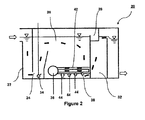
- FIG. 2 illustrates a preferred embodiment of the DAF device 20 of the present invention.
- Device 20 includes an influent zone 22, a contact zone 24, a separation zone 26, a sludge collection chamber 28, and an effluent zone 32. All of the zones are in fluid communication with one another and the collection chamber.
- Influent zone 22 includes an inlet to receive a volume of fluid to be clarified. This fluid is most typically water. The water can be purified to create, for example, drinking water. The processing of other fluids, and for other purposes, is within the scope of the present invention.
- DAF device 20 substantially removes the impurities from the influent to form sludge and a volume of clarified effluent.
- Contact zone 24 is defined by upper and lower extents.
- a series of pressure release nozzles 34 are positioned at the lower extent.
- Nozzle header 34 receives pressurized liquid saturated with air and distributes it evenly to each nozzle.
- nozzles 34 may be connected to a pressurized source of air. In either event, as the liquid or air passes the nozzles, micro-bubbles are generated. Ideally, nozzles 34 are sized such that very fine bubbles are created. Once formed, the buoyancy of the bubbles carries them to the top of DAF device 20. While in contact zone 24, the bubbles contact and agglomerating with the impurities in the influent. This results in larger agglomerated particles that are nonetheless buoyant.
- the inlet baffle to the separation zone 26 is preferably inclined. The inclination of the inlet baffle increases the contact zone area from bottom to top. The increase in contact zone area reduces the flow velocity and therefore turbulence.
- the agglomerated particles travel into separation zone 26 where they raise to the upper extent of separation zone 26.
- Collection chamber 28 is positioned adjacent the upper extent of separation zone 26. The agglomerated particles are gathered into the collection chamber as sludge. Once the impurities are removed from the influent, the remaining effluent flows downwardly to the lower extent of separation zone 26.
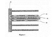
- header 36 includes a series of interconnected collection and discharge channels (38 and 42). Both header 36 and the collection and discharge channels (38 and 42) are positioned within the lower extent of separation zone 26. In a preferred by non-limiting example, the collection and discharge channels (38 and 42) are perpendicular to header 36.
- Each of the collection channels 38 includes a series of intake apertures 44. Intake apertures 44 are arrayed on the bottom of a respective collection channel 38 and therefore face the bottom of separation zone 26 and the DAF device 20. The effluent travels to the very bottom of separation zone 26 before entering the intake apertures 44 within collection channels 38.
- the suction at the outer end of the collection channel 38 (the end opposite header 36) is less than the suction at the inner end of the collection channel 38 (the end adjacent header 36).
- This pressure differential operates to further the path of the agglomerated particles and allows the agglomerated particles to rise to the collection chamber 28.
- the effluent is collected and routed to one of the discharge channels 42. As illustrated in FIGS. 3-4 , there are preferably fewer discharge channels 42 but they have an increased diameter. The total volumetric output of the discharge channels 42 should equal the volumetric input of the collection channels 38. Effluent zone 32 is in fluid communication with each of the discharge channels 42. Accordingly, effluent leaving header 36 is delivered to effluent zone 32 by way of the discharge channels 42. This clarified fluid can then be passed to additional processing steps.
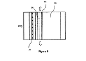
- FIGS. 5-9 Various alternative embodiments are depicted in FIGS. 5-9 .
- the collection and discharge channels (38 and 42) have been eliminated. Additionally, the intake apertures 44 are formed along the bottom of header 36 and the opposite ends of header 36 are opened. Thus, effluent is delivered directly into header 36. The effluent then exits through the opposite, opened ends of the header 36 as noted in FIG. 6 . Effluent zones 32 are, therefore, formed on either side of the device.
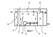
- FIG. 7 is a further alternative embodiment which is the same in most respects as the primary embodiment.
- header 36 includes discharge channels 42 but no collection channels 38.
- the effluent is delivered into header 36 via intake apertures 44 formed along the bottom of header 36.
- Apertures 44 can be formed as openings, holes, or continuous slits (lengthwise or laterally).
- Discharge channels 42 then route the collected effluent into effluent zone 32. This embodiment eliminates the need for separate collection channels 38 as well as side mounted effluent zones 32.
- header 36 includes collection channels 38 but no discharge channels 42.
- Collection channels 38 are the same as those described in connection with the preferred embodiment. Namely, collection channels 38 include a number of intake apertures 44 formed along their bottom surface. These intake apertures 44 collect effluent, which is then delivered to header 36 via the respective collection channels 38. As most clearly illustrated in FIG. 9 , the collected effluent is then delivered to opposing effluent zones via the opposite, opened ends of header 36.
Landscapes
- Life Sciences & Earth Sciences (AREA)
- Engineering & Computer Science (AREA)
- Biotechnology (AREA)
- Hydrology & Water Resources (AREA)
- Environmental & Geological Engineering (AREA)
- Water Supply & Treatment (AREA)
- Chemical & Material Sciences (AREA)
- Organic Chemistry (AREA)
- Physical Water Treatments (AREA)
Applications Claiming Priority (1)
| Application Number | Priority Date | Filing Date | Title |
|---|---|---|---|
| US13/869,129 US9422168B2 (en) | 2013-04-24 | 2013-04-24 | Dissolved air flotation device for liquid clarification |
Publications (2)
| Publication Number | Publication Date |
|---|---|
| EP2796178A1 true EP2796178A1 (de) | 2014-10-29 |
| EP2796178B1 EP2796178B1 (de) | 2018-11-28 |
Family
ID=50513157
Family Applications (1)
| Application Number | Title | Priority Date | Filing Date |
|---|---|---|---|
| EP14165628.0A Active EP2796178B1 (de) | 2013-04-24 | 2014-04-23 | Entspannungsflotationsvorrichtung zum Klären von Flüssigkeit |
Country Status (3)
| Country | Link |
|---|---|
| US (1) | US9422168B2 (de) |
| EP (1) | EP2796178B1 (de) |
| KR (1) | KR102253000B1 (de) |
Cited By (3)
| Publication number | Priority date | Publication date | Assignee | Title |
|---|---|---|---|---|
| CN104291497A (zh) * | 2014-11-03 | 2015-01-21 | 山东建筑大学 | 一种共聚气浮澄清池 |
| EP3120914A1 (de) * | 2015-07-24 | 2017-01-25 | Mahle International GmbH | Filtereinrichtung |
| ES2606102A1 (es) * | 2015-09-21 | 2017-03-22 | Proyectos Y Sistemas Medioambientales, S.L. | Método y sistema de tratamiento de aguas residuales para tanques de flotación |
Families Citing this family (7)
| Publication number | Priority date | Publication date | Assignee | Title |
|---|---|---|---|---|
| CA2963306C (en) * | 2014-10-02 | 2022-08-30 | Veolia Water Solutions & Technologies Support | Water treatment process employing dissolved air flotation to remove suspended solids |
| WO2018085763A1 (en) | 2016-11-06 | 2018-05-11 | Nap Kyle | System and method for liquid processing |
| US10851004B2 (en) | 2017-04-12 | 2020-12-01 | Seaon, LLC | Waste water treatment method and apparatus |
| WO2019226725A1 (en) | 2018-05-24 | 2019-11-28 | Nap Kyle | Portable modular filter system |
| WO2020041198A1 (en) * | 2018-08-24 | 2020-02-27 | Fluid Technology Solutions (Fts), Inc. | Methods for air flotation removal of highly fouling compounds from biodigester or animal waste |
| KR102162015B1 (ko) | 2020-07-16 | 2020-10-06 | 효림산업주식회사 | 임시침전지구조를 갖는 아치형 부상분리장치 |
| KR102302018B1 (ko) * | 2021-04-01 | 2021-09-15 | 해성엔지니어링 주식회사 | 접촉산화반응조 및 이를 포함하는 하수처리 시스템 |
Citations (7)
| Publication number | Priority date | Publication date | Assignee | Title |
|---|---|---|---|---|
| US3175687A (en) | 1962-09-24 | 1965-03-30 | Komline Sanderson Eng Corp | Flotation unit |
| US3870635A (en) * | 1972-12-13 | 1975-03-11 | Improved Machinery Inc | Apparatus for clarifying an influent water |
| US5047149A (en) | 1989-06-01 | 1991-09-10 | Degremont | Apparatus for the clarification of liquids, such as notably water, fruit juices, grape must or similar |
| WO1996029134A1 (en) * | 1995-03-23 | 1996-09-26 | Les Traitements Des Eaux Poseidon Inc. | Method and apparatus for separating non-soluble particles from a liquid |
| US20090211974A1 (en) | 2005-09-09 | 2009-08-27 | Degremont | Water clarifying apparatus and implementing method |
| US20110114565A1 (en) * | 2009-11-16 | 2011-05-19 | Roberts R Lee | Dissolved air flotation clarifier |
| US20120211431A1 (en) * | 2011-02-17 | 2012-08-23 | Sionix Corporation | Dissolved Air Flotation System with Bubble Separation System and Method of Use |
Family Cites Families (21)
| Publication number | Priority date | Publication date | Assignee | Title |
|---|---|---|---|---|
| US2765919A (en) * | 1952-04-23 | 1956-10-09 | Juell Fredrik | Process for the separation of suspended material from water by flotation and apparatus therefor |
| US4681682A (en) * | 1983-07-26 | 1987-07-21 | Alar Engineering Corporation | Air flotation clarifier |
| FR2759720B1 (fr) | 1997-02-19 | 1999-04-30 | Degremont | Procede de realisation d'un plancher de filtre pour le traitement des eaux |
| US6890431B1 (en) | 2000-02-18 | 2005-05-10 | The F. B. Leopold Co., Inc. | Buoyant media flotation |
| FR2835247B1 (fr) | 2002-01-30 | 2005-01-28 | Ondeo Degremont | Installation de traitement d'eaux par flottation |
| FR2837197B1 (fr) | 2002-03-12 | 2005-01-28 | Ondeo Degremont | Procede et dispositif de clarification de liquides, notamment d'eaux, charges de matieres en suspension |
| US7033495B2 (en) | 2003-02-27 | 2006-04-25 | Sionix Corporation | Self contained dissolved air flotation system |
| DE60316996T2 (de) | 2003-04-16 | 2008-07-24 | Ondeo Degremont | Anlage zur behandlung von wasser mittels flotation |
| FR2860735B1 (fr) | 2003-10-10 | 2006-12-22 | Degremont | Buse de detente d'eau pressurisee pour generer des microbules dans une installation de flottation |
| US20070114182A1 (en) * | 2005-11-18 | 2007-05-24 | Hydroxyl Systems Inc. | Wastewater treatment system for a marine vessel |
| FR2909993B1 (fr) | 2006-12-13 | 2010-12-10 | Degremont | Procede pour la clarification par flottation d'eaux difficiles, et installation pour sa mise en oeuvre |
| US8133396B2 (en) | 2007-01-11 | 2012-03-13 | Smith & Loveless, Inc. | Dissolved air floatation with filter system |
| US8715512B2 (en) | 2007-04-03 | 2014-05-06 | Siemens Energy, Inc. | Systems and methods for liquid separation |
| ITRE20070056A1 (it) | 2007-04-20 | 2008-10-21 | Acqua & Co S R L | Unita' di trattamento di acqua |
| KR100882200B1 (ko) | 2008-06-03 | 2009-02-06 | 주식회사 한국아쿠오시스 | 하이드로사이클론 및 이것을 포함하는 수질오염 방지장치 |
| FR2934582B1 (fr) | 2008-07-29 | 2010-09-10 | Otv Sa | Procede de traitement d'un liquide par flottation induite par des particules flottantes. |
| US8114296B2 (en) | 2009-04-23 | 2012-02-14 | Fang Chao | Method and apparatus for skimming floated sludge |
| GB0917642D0 (en) | 2009-10-09 | 2009-11-25 | Enpure Ltd | Dissolved gas floatation pressure reduction nozzle |
| FR2971432B1 (fr) * | 2011-02-15 | 2013-03-22 | Saur | Installation pour traitement d'eau par flottation et procede associe |
| US20120211905A1 (en) | 2011-02-17 | 2012-08-23 | Sionix Corporation | Dissolved Air Flotation System with Improved White Water Injection System |
| US20120211407A1 (en) | 2011-02-17 | 2012-08-23 | Sionix Corporation | Dissolved Air Flotation Nozzle for Use With Self Contained Dissolved Air Flotation System |
-
2013
- 2013-04-24 US US13/869,129 patent/US9422168B2/en active Active
-
2014
- 2014-04-23 EP EP14165628.0A patent/EP2796178B1/de active Active
- 2014-04-24 KR KR1020140049409A patent/KR102253000B1/ko active Active
Patent Citations (7)
| Publication number | Priority date | Publication date | Assignee | Title |
|---|---|---|---|---|
| US3175687A (en) | 1962-09-24 | 1965-03-30 | Komline Sanderson Eng Corp | Flotation unit |
| US3870635A (en) * | 1972-12-13 | 1975-03-11 | Improved Machinery Inc | Apparatus for clarifying an influent water |
| US5047149A (en) | 1989-06-01 | 1991-09-10 | Degremont | Apparatus for the clarification of liquids, such as notably water, fruit juices, grape must or similar |
| WO1996029134A1 (en) * | 1995-03-23 | 1996-09-26 | Les Traitements Des Eaux Poseidon Inc. | Method and apparatus for separating non-soluble particles from a liquid |
| US20090211974A1 (en) | 2005-09-09 | 2009-08-27 | Degremont | Water clarifying apparatus and implementing method |
| US20110114565A1 (en) * | 2009-11-16 | 2011-05-19 | Roberts R Lee | Dissolved air flotation clarifier |
| US20120211431A1 (en) * | 2011-02-17 | 2012-08-23 | Sionix Corporation | Dissolved Air Flotation System with Bubble Separation System and Method of Use |
Cited By (4)
| Publication number | Priority date | Publication date | Assignee | Title |
|---|---|---|---|---|
| CN104291497A (zh) * | 2014-11-03 | 2015-01-21 | 山东建筑大学 | 一种共聚气浮澄清池 |
| CN104291497B (zh) * | 2014-11-03 | 2015-12-02 | 山东建筑大学 | 一种共聚气浮澄清池 |
| EP3120914A1 (de) * | 2015-07-24 | 2017-01-25 | Mahle International GmbH | Filtereinrichtung |
| ES2606102A1 (es) * | 2015-09-21 | 2017-03-22 | Proyectos Y Sistemas Medioambientales, S.L. | Método y sistema de tratamiento de aguas residuales para tanques de flotación |
Also Published As
| Publication number | Publication date |
|---|---|
| US20140319036A1 (en) | 2014-10-30 |
| KR20140127180A (ko) | 2014-11-03 |
| KR102253000B1 (ko) | 2021-05-17 |
| US9422168B2 (en) | 2016-08-23 |
| EP2796178B1 (de) | 2018-11-28 |
Similar Documents
| Publication | Publication Date | Title |
|---|---|---|
| US9422168B2 (en) | Dissolved air flotation device for liquid clarification | |
| US4986903A (en) | Induced static single flotation cell | |
| KR101722099B1 (ko) | 미세기포의 안정적 발생구조를 가진 부상분리식 하수처리장치 | |
| EP1735070B1 (de) | Trennvorrichtung | |
| US5011597A (en) | Single cell vertical static flow flotation unit | |
| US4277347A (en) | Method for making flotable, particles suspended in a liquid by means of gas bubbles | |
| EP0814885B1 (de) | Verfahren und vorrichtung zur trennung von nicht löslichen teilchen aus einer flüssigkeit | |
| EP2408533B1 (de) | Verbesserte vorrichtung zur kombinierten gasentfernung, schmutzentfernung und entfernung von kontaminierenden flüssigkeiten | |
| US5080780A (en) | Single cell vertical static flow flotation unit cross-reference to related applications | |
| RU2641926C2 (ru) | Резервуар для газовой флотации | |
| US8231008B2 (en) | Column flotation cell for enhanced recovery of minerals such as phosphates by froth flotation | |
| CN106984071A (zh) | 废水沉淀池及废水沉淀方法 | |
| KR101936181B1 (ko) | 다단형 가압부상조 | |
| KR101773379B1 (ko) | 사이클론을 포함하는 수평형 유도가스 부상분리를 이용한 유수처리 장치 및 그 방법 | |
| EP0826404B1 (de) | Behälter zum Entgasen von Wasser | |
| CN107986391A (zh) | 复合型高效油水分离装置 | |
| US20190366355A1 (en) | Apparatus For Direct Recovery of Mineral Values As A Bubble-Solids Aggregate | |
| US4720341A (en) | Water treating in a vertical series coalescing flume | |
| CN203360063U (zh) | 一种油田含油污水高效除油聚结装置 | |
| US1380665A (en) | lyster | |
| CN107540049A (zh) | 一种含油污水分离器 | |
| KR102367543B1 (ko) | 유공블록형 하부집수장치가 적용된 여과지 | |
| CN114105288B (zh) | 一种自循环连续流好氧颗粒污泥滤沉装置 | |
| CN216837365U (zh) | 一种废水处理装置 | |
| KR101773378B1 (ko) | 미스트제거기를 포함하는 수평형유도가스 부상분리 유수처리 장치 및 그 방법 |
Legal Events
| Date | Code | Title | Description |
|---|---|---|---|
| PUAI | Public reference made under article 153(3) epc to a published international application that has entered the european phase |
Free format text: ORIGINAL CODE: 0009012 |
|
| 17P | Request for examination filed |
Effective date: 20140423 |
|
| AK | Designated contracting states |
Kind code of ref document: A1 Designated state(s): AL AT BE BG CH CY CZ DE DK EE ES FI FR GB GR HR HU IE IS IT LI LT LU LV MC MK MT NL NO PL PT RO RS SE SI SK SM TR |
|
| AX | Request for extension of the european patent |
Extension state: BA ME |
|
| R17P | Request for examination filed (corrected) |
Effective date: 20150429 |
|
| RBV | Designated contracting states (corrected) |
Designated state(s): AL AT BE BG CH CY CZ DE DK EE ES FI FR GB GR HR HU IE IS IT LI LT LU LV MC MK MT NL NO PL PT RO RS SE SI SK SM TR |
|
| STAA | Information on the status of an ep patent application or granted ep patent |
Free format text: STATUS: EXAMINATION IS IN PROGRESS |
|
| 17Q | First examination report despatched |
Effective date: 20170104 |
|
| GRAP | Despatch of communication of intention to grant a patent |
Free format text: ORIGINAL CODE: EPIDOSNIGR1 |
|
| STAA | Information on the status of an ep patent application or granted ep patent |
Free format text: STATUS: GRANT OF PATENT IS INTENDED |
|
| INTG | Intention to grant announced |
Effective date: 20180613 |
|
| RAP1 | Party data changed (applicant data changed or rights of an application transferred) |
Owner name: DOOSAN HEAVY INDUSTRIES & CONSTRUCTION CO., LTD. |
|
| GRAS | Grant fee paid |
Free format text: ORIGINAL CODE: EPIDOSNIGR3 |
|
| GRAA | (expected) grant |
Free format text: ORIGINAL CODE: 0009210 |
|
| STAA | Information on the status of an ep patent application or granted ep patent |
Free format text: STATUS: THE PATENT HAS BEEN GRANTED |
|
| AK | Designated contracting states |
Kind code of ref document: B1 Designated state(s): AL AT BE BG CH CY CZ DE DK EE ES FI FR GB GR HR HU IE IS IT LI LT LU LV MC MK MT NL NO PL PT RO RS SE SI SK SM TR |
|
| REG | Reference to a national code |
Ref country code: CH Ref legal event code: EP |
|
| REG | Reference to a national code |
Ref country code: AT Ref legal event code: REF Ref document number: 1069568 Country of ref document: AT Kind code of ref document: T Effective date: 20181215 |
|
| REG | Reference to a national code |
Ref country code: DE Ref legal event code: R096 Ref document number: 602014036798 Country of ref document: DE |
|
| REG | Reference to a national code |
Ref country code: IE Ref legal event code: FG4D |
|
| REG | Reference to a national code |
Ref country code: NL Ref legal event code: MP Effective date: 20181128 |
|
| REG | Reference to a national code |
Ref country code: LT Ref legal event code: MG4D |
|
| REG | Reference to a national code |
Ref country code: AT Ref legal event code: MK05 Ref document number: 1069568 Country of ref document: AT Kind code of ref document: T Effective date: 20181128 |
|
| PG25 | Lapsed in a contracting state [announced via postgrant information from national office to epo] |
Ref country code: FI Free format text: LAPSE BECAUSE OF FAILURE TO SUBMIT A TRANSLATION OF THE DESCRIPTION OR TO PAY THE FEE WITHIN THE PRESCRIBED TIME-LIMIT Effective date: 20181128 Ref country code: LV Free format text: LAPSE BECAUSE OF FAILURE TO SUBMIT A TRANSLATION OF THE DESCRIPTION OR TO PAY THE FEE WITHIN THE PRESCRIBED TIME-LIMIT Effective date: 20181128 Ref country code: AT Free format text: LAPSE BECAUSE OF FAILURE TO SUBMIT A TRANSLATION OF THE DESCRIPTION OR TO PAY THE FEE WITHIN THE PRESCRIBED TIME-LIMIT Effective date: 20181128 Ref country code: HR Free format text: LAPSE BECAUSE OF FAILURE TO SUBMIT A TRANSLATION OF THE DESCRIPTION OR TO PAY THE FEE WITHIN THE PRESCRIBED TIME-LIMIT Effective date: 20181128 Ref country code: BG Free format text: LAPSE BECAUSE OF FAILURE TO SUBMIT A TRANSLATION OF THE DESCRIPTION OR TO PAY THE FEE WITHIN THE PRESCRIBED TIME-LIMIT Effective date: 20190228 Ref country code: ES Free format text: LAPSE BECAUSE OF FAILURE TO SUBMIT A TRANSLATION OF THE DESCRIPTION OR TO PAY THE FEE WITHIN THE PRESCRIBED TIME-LIMIT Effective date: 20181128 Ref country code: NO Free format text: LAPSE BECAUSE OF FAILURE TO SUBMIT A TRANSLATION OF THE DESCRIPTION OR TO PAY THE FEE WITHIN THE PRESCRIBED TIME-LIMIT Effective date: 20190228 Ref country code: LT Free format text: LAPSE BECAUSE OF FAILURE TO SUBMIT A TRANSLATION OF THE DESCRIPTION OR TO PAY THE FEE WITHIN THE PRESCRIBED TIME-LIMIT Effective date: 20181128 Ref country code: IS Free format text: LAPSE BECAUSE OF FAILURE TO SUBMIT A TRANSLATION OF THE DESCRIPTION OR TO PAY THE FEE WITHIN THE PRESCRIBED TIME-LIMIT Effective date: 20190328 |
|
| PG25 | Lapsed in a contracting state [announced via postgrant information from national office to epo] |
Ref country code: PT Free format text: LAPSE BECAUSE OF FAILURE TO SUBMIT A TRANSLATION OF THE DESCRIPTION OR TO PAY THE FEE WITHIN THE PRESCRIBED TIME-LIMIT Effective date: 20190328 Ref country code: GR Free format text: LAPSE BECAUSE OF FAILURE TO SUBMIT A TRANSLATION OF THE DESCRIPTION OR TO PAY THE FEE WITHIN THE PRESCRIBED TIME-LIMIT Effective date: 20190301 Ref country code: RS Free format text: LAPSE BECAUSE OF FAILURE TO SUBMIT A TRANSLATION OF THE DESCRIPTION OR TO PAY THE FEE WITHIN THE PRESCRIBED TIME-LIMIT Effective date: 20181128 Ref country code: SE Free format text: LAPSE BECAUSE OF FAILURE TO SUBMIT A TRANSLATION OF THE DESCRIPTION OR TO PAY THE FEE WITHIN THE PRESCRIBED TIME-LIMIT Effective date: 20181128 Ref country code: AL Free format text: LAPSE BECAUSE OF FAILURE TO SUBMIT A TRANSLATION OF THE DESCRIPTION OR TO PAY THE FEE WITHIN THE PRESCRIBED TIME-LIMIT Effective date: 20181128 |
|
| PG25 | Lapsed in a contracting state [announced via postgrant information from national office to epo] |
Ref country code: NL Free format text: LAPSE BECAUSE OF FAILURE TO SUBMIT A TRANSLATION OF THE DESCRIPTION OR TO PAY THE FEE WITHIN THE PRESCRIBED TIME-LIMIT Effective date: 20181128 |
|
| PG25 | Lapsed in a contracting state [announced via postgrant information from national office to epo] |
Ref country code: IT Free format text: LAPSE BECAUSE OF FAILURE TO SUBMIT A TRANSLATION OF THE DESCRIPTION OR TO PAY THE FEE WITHIN THE PRESCRIBED TIME-LIMIT Effective date: 20181128 Ref country code: CZ Free format text: LAPSE BECAUSE OF FAILURE TO SUBMIT A TRANSLATION OF THE DESCRIPTION OR TO PAY THE FEE WITHIN THE PRESCRIBED TIME-LIMIT Effective date: 20181128 Ref country code: DK Free format text: LAPSE BECAUSE OF FAILURE TO SUBMIT A TRANSLATION OF THE DESCRIPTION OR TO PAY THE FEE WITHIN THE PRESCRIBED TIME-LIMIT Effective date: 20181128 Ref country code: PL Free format text: LAPSE BECAUSE OF FAILURE TO SUBMIT A TRANSLATION OF THE DESCRIPTION OR TO PAY THE FEE WITHIN THE PRESCRIBED TIME-LIMIT Effective date: 20181128 |
|
| REG | Reference to a national code |
Ref country code: DE Ref legal event code: R097 Ref document number: 602014036798 Country of ref document: DE |
|
| PG25 | Lapsed in a contracting state [announced via postgrant information from national office to epo] |
Ref country code: EE Free format text: LAPSE BECAUSE OF FAILURE TO SUBMIT A TRANSLATION OF THE DESCRIPTION OR TO PAY THE FEE WITHIN THE PRESCRIBED TIME-LIMIT Effective date: 20181128 Ref country code: SM Free format text: LAPSE BECAUSE OF FAILURE TO SUBMIT A TRANSLATION OF THE DESCRIPTION OR TO PAY THE FEE WITHIN THE PRESCRIBED TIME-LIMIT Effective date: 20181128 Ref country code: SK Free format text: LAPSE BECAUSE OF FAILURE TO SUBMIT A TRANSLATION OF THE DESCRIPTION OR TO PAY THE FEE WITHIN THE PRESCRIBED TIME-LIMIT Effective date: 20181128 Ref country code: RO Free format text: LAPSE BECAUSE OF FAILURE TO SUBMIT A TRANSLATION OF THE DESCRIPTION OR TO PAY THE FEE WITHIN THE PRESCRIBED TIME-LIMIT Effective date: 20181128 |
|
| PLBE | No opposition filed within time limit |
Free format text: ORIGINAL CODE: 0009261 |
|
| STAA | Information on the status of an ep patent application or granted ep patent |
Free format text: STATUS: NO OPPOSITION FILED WITHIN TIME LIMIT |
|
| PG25 | Lapsed in a contracting state [announced via postgrant information from national office to epo] |
Ref country code: SI Free format text: LAPSE BECAUSE OF FAILURE TO SUBMIT A TRANSLATION OF THE DESCRIPTION OR TO PAY THE FEE WITHIN THE PRESCRIBED TIME-LIMIT Effective date: 20181128 |
|
| 26N | No opposition filed |
Effective date: 20190829 |
|
| REG | Reference to a national code |
Ref country code: CH Ref legal event code: PL |
|
| REG | Reference to a national code |
Ref country code: BE Ref legal event code: MM Effective date: 20190430 |
|
| GBPC | Gb: european patent ceased through non-payment of renewal fee |
Effective date: 20190423 |
|
| PG25 | Lapsed in a contracting state [announced via postgrant information from national office to epo] |
Ref country code: MC Free format text: LAPSE BECAUSE OF FAILURE TO SUBMIT A TRANSLATION OF THE DESCRIPTION OR TO PAY THE FEE WITHIN THE PRESCRIBED TIME-LIMIT Effective date: 20181128 Ref country code: LU Free format text: LAPSE BECAUSE OF NON-PAYMENT OF DUE FEES Effective date: 20190423 |
|
| PG25 | Lapsed in a contracting state [announced via postgrant information from national office to epo] |
Ref country code: GB Free format text: LAPSE BECAUSE OF NON-PAYMENT OF DUE FEES Effective date: 20190423 Ref country code: CH Free format text: LAPSE BECAUSE OF NON-PAYMENT OF DUE FEES Effective date: 20190430 Ref country code: LI Free format text: LAPSE BECAUSE OF NON-PAYMENT OF DUE FEES Effective date: 20190430 |
|
| PG25 | Lapsed in a contracting state [announced via postgrant information from national office to epo] |
Ref country code: BE Free format text: LAPSE BECAUSE OF NON-PAYMENT OF DUE FEES Effective date: 20190430 |
|
| PG25 | Lapsed in a contracting state [announced via postgrant information from national office to epo] |
Ref country code: TR Free format text: LAPSE BECAUSE OF FAILURE TO SUBMIT A TRANSLATION OF THE DESCRIPTION OR TO PAY THE FEE WITHIN THE PRESCRIBED TIME-LIMIT Effective date: 20181128 |
|
| PG25 | Lapsed in a contracting state [announced via postgrant information from national office to epo] |
Ref country code: IE Free format text: LAPSE BECAUSE OF NON-PAYMENT OF DUE FEES Effective date: 20190423 |
|
| PG25 | Lapsed in a contracting state [announced via postgrant information from national office to epo] |
Ref country code: CY Free format text: LAPSE BECAUSE OF FAILURE TO SUBMIT A TRANSLATION OF THE DESCRIPTION OR TO PAY THE FEE WITHIN THE PRESCRIBED TIME-LIMIT Effective date: 20181128 |
|
| PG25 | Lapsed in a contracting state [announced via postgrant information from national office to epo] |
Ref country code: MT Free format text: LAPSE BECAUSE OF FAILURE TO SUBMIT A TRANSLATION OF THE DESCRIPTION OR TO PAY THE FEE WITHIN THE PRESCRIBED TIME-LIMIT Effective date: 20181128 Ref country code: HU Free format text: LAPSE BECAUSE OF FAILURE TO SUBMIT A TRANSLATION OF THE DESCRIPTION OR TO PAY THE FEE WITHIN THE PRESCRIBED TIME-LIMIT; INVALID AB INITIO Effective date: 20140423 |
|
| PG25 | Lapsed in a contracting state [announced via postgrant information from national office to epo] |
Ref country code: MK Free format text: LAPSE BECAUSE OF FAILURE TO SUBMIT A TRANSLATION OF THE DESCRIPTION OR TO PAY THE FEE WITHIN THE PRESCRIBED TIME-LIMIT Effective date: 20181128 |
|
| PGFP | Annual fee paid to national office [announced via postgrant information from national office to epo] |
Ref country code: DE Payment date: 20250225 Year of fee payment: 12 |
|
| PGFP | Annual fee paid to national office [announced via postgrant information from national office to epo] |
Ref country code: FR Payment date: 20260309 Year of fee payment: 13 |