EP2796238B1 - Dispositif de mesure et installation de traitement du bois dotée d'un tel dispositif de mesure - Google Patents
Dispositif de mesure et installation de traitement du bois dotée d'un tel dispositif de mesure Download PDFInfo
- Publication number
- EP2796238B1 EP2796238B1 EP14160925.5A EP14160925A EP2796238B1 EP 2796238 B1 EP2796238 B1 EP 2796238B1 EP 14160925 A EP14160925 A EP 14160925A EP 2796238 B1 EP2796238 B1 EP 2796238B1
- Authority
- EP
- European Patent Office
- Prior art keywords
- belt
- measurement apparatus
- workpiece
- chain
- carrier
- Prior art date
- Legal status (The legal status is an assumption and is not a legal conclusion. Google has not performed a legal analysis and makes no representation as to the accuracy of the status listed.)
- Active
Links
Images

Classifications
-
- G—PHYSICS
- G01—MEASURING; TESTING
- G01P—MEASURING LINEAR OR ANGULAR SPEED, ACCELERATION, DECELERATION, OR SHOCK; INDICATING PRESENCE, ABSENCE, OR DIRECTION, OF MOVEMENT
- G01P1/00—Details of instruments
- G01P1/04—Special adaptations of driving means
-
- B—PERFORMING OPERATIONS; TRANSPORTING
- B23—MACHINE TOOLS; METAL-WORKING NOT OTHERWISE PROVIDED FOR
- B23Q—DETAILS, COMPONENTS, OR ACCESSORIES FOR MACHINE TOOLS, e.g. ARRANGEMENTS FOR COPYING OR CONTROLLING; MACHINE TOOLS IN GENERAL CHARACTERISED BY THE CONSTRUCTION OF PARTICULAR DETAILS OR COMPONENTS; COMBINATIONS OR ASSOCIATIONS OF METAL-WORKING MACHINES, NOT DIRECTED TO A PARTICULAR RESULT
- B23Q17/00—Arrangements for observing, indicating or measuring on machine tools
- B23Q17/22—Arrangements for observing, indicating or measuring on machine tools for indicating or measuring existing or desired position of tool or work
-
- B—PERFORMING OPERATIONS; TRANSPORTING
- B23—MACHINE TOOLS; METAL-WORKING NOT OTHERWISE PROVIDED FOR
- B23Q—DETAILS, COMPONENTS, OR ACCESSORIES FOR MACHINE TOOLS, e.g. ARRANGEMENTS FOR COPYING OR CONTROLLING; MACHINE TOOLS IN GENERAL CHARACTERISED BY THE CONSTRUCTION OF PARTICULAR DETAILS OR COMPONENTS; COMBINATIONS OR ASSOCIATIONS OF METAL-WORKING MACHINES, NOT DIRECTED TO A PARTICULAR RESULT
- B23Q7/00—Arrangements for handling work specially combined with or arranged in, or specially adapted for use in connection with, machine tools, e.g. for conveying, loading, positioning, discharging, sorting
- B23Q7/03—Arrangements for handling work specially combined with or arranged in, or specially adapted for use in connection with, machine tools, e.g. for conveying, loading, positioning, discharging, sorting by means of endless chain conveyors
-
- B—PERFORMING OPERATIONS; TRANSPORTING
- B27—WORKING OR PRESERVING WOOD OR SIMILAR MATERIAL; NAILING OR STAPLING MACHINES IN GENERAL
- B27C—PLANING, DRILLING, MILLING, TURNING OR UNIVERSAL MACHINES FOR WOOD OR SIMILAR MATERIAL
- B27C1/00—Machines for producing flat surfaces, e.g. by rotary cutters; Equipment therefor
- B27C1/12—Arrangements for feeding work
Definitions
- the invention relates to a measuring device for detecting the feed movement of a workpiece to be machined according to the preamble of claim 1.
- the invention also relates to a woodworking machine with such a measuring device.
- Such a measuring device is off EP 0185788 A1 known.
- Such a measuring device is known from DE 20 2011 105 077 U1 known.
- the feed movement of a workpiece is detected by a belt assembly with a guided over pulleys and pressed against the workpiece belt.
- the belt is pressed by the moving together with these pressure elements, for example, to the underside of a moving workpiece on a workpiece in the longitudinal direction.
- the pressure elements which are moved along with the belt, the belt can be pressed against the workpiece in order to achieve a slip-free connection to the workpiece without a sliding friction occurring between the pressure element and the belt.
- a sensor or other suitable means for detecting the rotational movement may be arranged on at least one of the deflection pulleys of the belt.
- a cable transport device for a Jardinablablnature- and Jardinisoliervorides is known. This has a guided on a support via pulleys timing belt, which is pressed against a cable to be transported. In order to achieve a uniform contact pressure on the cable, more pressure rollers are provided between the pulleys.
- the carrier is also rotatable on a holder about a perpendicular to the direction of movement of the toothed belt pivot axis, so that it can perform a pendulum motion.
- a sensor designed as a measuring roller is furthermore provided in front of the cable transport device, with which the length of the cable passing through can be determined.
- the object of the invention is to provide a measuring device and equipped with such a measuring device woodworking system, which allow the most accurate detection of the feed movement of a workpiece.
- the two lying in a plane Kettenumlenkiza are suitably arranged in a plane between the two pulleys of the belt such that the pressure elements come to rest on the inside of the arranged between the two deflectors Rootrums the belt.
- the fact that the pressure elements move with the belt or the chain, the belt or the chain can be pressed against the workpiece to achieve a slip-free connection with the workpiece without a sliding friction between the pressure element and the belt or the chain occurs.
- the pressure device could also be designed as a co-moving belt.
- the pivot axis of the carrier lies in a region which extends from a plane formed by the axes of rotation of the deflecting disks in the direction of an abutment belt formed by the belt or chain to bear against the workpiece.
- the pivot axis is arranged on the outer side of the contactor formed by the belt or the chain for contact with the workpiece in the middle between the two deflection plates.
- An accurate and stable mounting of the carrier can be achieved, for example, in that the carrier has a convex bearing part in a corresponding, concave bearing shell is stored.
- the bearing shell can protrude through an opening of the carrier and be attached to the holder.
- a displacement of the belt or the chain in the direction of the workpiece or from this away can be achieved in that the holder is slidably guided via a linear guide on a frame and adjustable by a drive.
- the pressure elements are pressed by a pressure plate against the inside of the belt.
- the pressure plate may be disposed between the Kettenumlenkrädem and is designed such that the pressure elements are pressed in the overflow on the pressure plate against the inside of the belt and this example. Press against the underside of a workpiece.
- the pressure plate may have a ramp-shaped course.
- the pressure plate can also be pivotable about a horizontal axis. As a result, the pressure elements can be pressed well even on irregular workpieces.
- rotatably mounted rollers can be arranged for resting on the pressure plate on the pressure elements or on the connecting elements between the pressure elements.
- the belt is guided over two arranged in a plane deflecting a staggered third disc, the third disc is pressed by springs against the inside of the belt.
- the measuring device described above is preferably used for detecting the movement of a workpiece on a plate processing plant, a joinery or similar woodworking plant.
- the belt or the chain is pressed by the moving together with these pressure elements, for example, to the underside of a moving on a workpiece support in the longitudinal direction of the workpiece.
- a sensor or other suitable means for detecting the rotational movement may be arranged on at least one of the deflection pulleys of the belt.
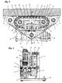
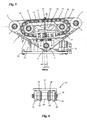
- the in the Figures 1 and 2 in a front and rear view measuring device shown here comprises a belt formed here as an endless belt 1, which is guided around two lying in a plane deflection pulleys 2 and 3 and a staggered third disc 4.
- the two deflecting disks 2 and 3 are rotatably mounted about axes of rotation 5 and 6 on a plate-shaped carrier 7.
- the disc 4 is within an in FIG. 1 recognizable receptacle 8 rotatably mounted about a rotation axis 9.
- the receptacle 8 is biased by two springs 10 mounted on a holder 7 fixed to the bracket 11. By the two springs 10, the receptacle 8 is pressed with the rotatably mounted therein disk 4 away from the holder 7 fixed to the bracket 11 against the inside of the belt 1, so that it is stretched.
- the two deflecting disks 2 and 3 and the disk 4 are designed as toothed disks for positive engagement with the belt 1 embodied here as an endless toothed belt 1 executed.
- the belt arrangement is designed in such a way that the region or run of the belt 1 extending between the two deflecting disks 2 and 3 acts as an abutment 16 for abutment against an in FIG. 3 shown workpiece 15 is used and with its outer side 17 at least partially comes to rest on a surface of the workpiece 15.
- the example as a wooden beam, wood board or the like.
- Performed workpiece 15 rests on a here formed by transport rollers roller conveyor or other suitable workpiece support 18 a plate processing plant or similar woodworking equipment and can be transported for processing by a transport device not shown along the workpiece support.
- the belt 1 is entrained by frictional engagement with the workpiece 15 and can be used to detect the movement of the workpiece 15.
- the belt assembly is in the embodiment shown so part of a measuring device for detecting the movement of the longitudinally moving workpiece 15, in which case the third disc 4 is connected to a rotary encoder or other suitable sensor 19 for detecting the rotational movement of the disc 4.
- detectable sensor 19 could also be attached to one of the deflecting plates 2 and 3.
- the carrier 7 is at an in FIG. 2 shown plate-shaped bracket 20 pivotally mounted such that it is perpendicular to a direction of movement of the belt 1 (in FIG. 5 perpendicular to the plane) pivot axis 21 is rotatable.
- the pivot axis 21 of the carrier 7 is located in a region which extends from a plane 22 formed by the axes of rotation 5 and 6 of the deflection plates 2 and 3 in the direction of the system formed by the belt 1 6.3trums 16.
- the pivot axis 21 is located in the middle between the two deflection disks 2 and 3 on the outer side 17 of the belt 1 formed for contact with the workpiece 15.
- the pivotability of the carrier 7 can be achieved by the carrier 7 is mounted via a convex bearing part 23 in a corresponding concave bearing shell 24.
- FIG. 4 It can be seen that the bearing shell 24 protrudes through an opening 25 of the carrier 7 and is secured to the plate-shaped holder 20.
- a delivery of the Belt 1 in the direction of the workpiece 15 is made possible in the embodiment shown in that the plate-shaped holder 20 is slidably guided via a linear guide on a frame formed from a bottom plate 26 and a bracket 27 and adjustable by a drive.
- the linear guide comprises a guide rail 28 fastened to the console 27 and a carriage 29 which is displaceably guided on the guide rail 28 and which slides in accordance with FIG FIG. 2 is attached to one end of the plate-shaped holder 20.
- the drive includes a hydraulically or pneumatically actuable actuating cylinder 30, whose piston rod is connected via a spring 31 and a retaining plate 32 with the other end of the plate-shaped holder 20.
- the carrier 7 can be raised or lowered relative to the base plate 26 and thus moved toward the workpiece 15 or away therefrom, whereby the contact pressure of the abutment 16 on the workpiece 14 can be changed.
- the contact margin 16 of the belt 1 is pressed by a pressure device 33 against the workpiece 15.
- the pressure device 33 includes a plurality of moving in the transport direction of the belt 1 with this Anyaketti 34, which are part of a guided around two Kettenumlenkiza 35 and 36 endless chain in the embodiment shown.
- the two on the support 7 rotatably mounted Kettenumlenkiza 35 and 36 are designed as gears.
- An horrimile 34 consist of a base body with an upper pressure member 37 and two downwardly projecting legs 38, through the two axes 39 with both sides rotatably mounted rollers 40 for resting on a in the Figures 3 and 5 shown pressure plate 41 run. By sitting on the ends of the axles 39 outer link plate 42, the rollers 40 are held.
- the pressure elements 11 are characterized by in FIG. 3 shown inner link plates 43 connected to the guided over the Kettenumlenkmann 35 and 36 endless chain. Between the inner link plates 43, a sleeve 44 is arranged.
- the pressure elements 34 slide as possible friction and wear on the pressure plate 41.
- the pressure plate 41 arranged between the chain deflection wheels 35 and 36 is designed in such a way that the pressure elements 34 are pressed against the belt 1 during the overflow via the pressure plate 41 and press it against the underside of the workpiece 7.
- the pressure plate 41 has a particularly in FIG. 3 recognizable ramp-shaped course with an inclined in the direction of movement of the pressing elements 34 to the pressing elements 34 towards the front ramp surface 45 and a sloping rear ramp surface 46.
- the measuring device described above is used for measuring the movement of a workpiece on a plate processing plant or a similar woodworking plant.
- the measuring device is integrated in a transport track or other workpiece support of the woodworking system so that the contact amount 16 of the belt 1 is e.g. comes to rest on the underside of resting on the transport path and transported in the longitudinal direction workpiece 15.
- the belt can also come to other side surfaces of the workpiece 15 to the plant. If the workpiece 15 is moved by a transport device, not shown here in the longitudinal direction, the pressed by the pressing elements 34 to the underside of the workpiece 15 belt 1 is taken due to the friction and transmits its movement to the disc 4, to which the sensor 19 for detecting the Rotary movement of the disc 4 is arranged. As a result, the feed movement of the workpiece 15 can be detected and measured. Since the pressure elements 34 move together with the belt 1 and there is no relative movement between pressure elements 34 and belt 1, no sliding friction occurs between the pressure elements 34 and the belt 1.
- the belt assembly could also be used to transport a workpiece, e.g. one or more of the deflection pulleys is driven. At the same time, a measurement of the movement of the workpiece can also be made here.
- a chain or similar tension elements could also be used, which are pressed against the workpiece 15 via the above-described pressing device 33 and pass through the workpiece 15 by means of suitable frictional or positive-locking elements in slip-free connection.
Landscapes
- Engineering & Computer Science (AREA)
- Mechanical Engineering (AREA)
- Life Sciences & Earth Sciences (AREA)
- Wood Science & Technology (AREA)
- Forests & Forestry (AREA)
- Physics & Mathematics (AREA)
- General Physics & Mathematics (AREA)
- Milling, Drilling, And Turning Of Wood (AREA)
- Dry Formation Of Fiberboard And The Like (AREA)
- Machine Tool Sensing Apparatuses (AREA)
- Control Of Conveyors (AREA)
Claims (14)
- Dispositif de mesure servant à détecter le déplacement d'avancement d'une pièce (15) à usiner, lequel contient une courroie (1) ou une chaîne guidée au niveau d'un système porteur (7) par l'intermédiaire de poulies de renvoi (2, 3), un système de pressage (33) déplacé par entraînement avec la courroie (1) ou la chaîne dans la direction de déplacement de cette dernière, servant à presser la courroie (1) ou la chaîne contre la pièce (1) et un capteur (19) servant à détecter le déplacement de la courroie (1) ou de la chaîne, dans lequel le système porteur (7) peut tourner au niveau d'un support (20) autour d'un axe de pivotement (21) situé à angle droit par rapport à la direction de déplacement de la courroie (1) ou de la chaîne, caractérisé en ce que le système de pressage (33) comprend plusieurs éléments de pressage (34) reliés les uns aux autres par des brides à chaîne (43) afin de former une chaîne sans fin et guidés par l'intermédiaire au moins de deux roues de renvoi de chaîne (35, 36).
- Dispositif de mesure selon la revendication 1, caractérisé en ce que l'axe de pivotement (21) du système porteur (7) se trouve dans une zone, qui s'étend depuis un plan (22) formé par les axes de rotation (5, 6) des poulies de renvoi (2, 3), en direction d'un brin d'appui (16) formé par la courroie (1) ou la chaîne, servant à venir en appui au niveau de la pièce à usiner (1).
- Dispositif de mesure selon la revendication 2, caractérisé en ce que l'axe de pivotement (21) se trouve sur le côté extérieur (17) réalisé pour venir en contact avec la pièce, du brin d'appui (16) formé par la courroie (1) ou la chaîne, au centre entre les deux poulies de renvoi (2, 3).
- Dispositif de mesure selon l'une quelconque des revendications 1 à 3, caractérisé en ce que le système porteur (7) est monté, par l'intermédiaire d'une partie formant palier (23) convexe, dans une coque formant palier (24) concave correspondant à la partie formant palier.
- Dispositif de mesure selon la revendication 4, caractérisé en ce que la coque formant palier (24) dépasse à travers une ouverture (25) du système porteur (7) et est fixée au niveau du support (20) en forme de plaque.
- Dispositif de mesure selon l'une quelconque des revendications 1 à 5, caractérisé en ce que le support (20) peut être guidé de manière à pouvoir coulisser au niveau d'un châssis (26, 27) par l'intermédiaire d'un guidage linéaire (28, 29) et peut être ajusté par un entraînement (30, 31).
- Dispositif de mesure selon la revendication 6, caractérisé en ce que le guidage linéaire (28, 29) comprend un rail de guidage (28) fixé au niveau d'une console (27) du châssis et un chariot (29) guidé de manière à pouvoir coulisser au niveau du rail de guidage (28), au niveau duquel le support (20) est fixé.
- Dispositif de mesure selon l'une quelconque des revendications 6 ou 7, caractérisé en ce que l'entraînement (30, 31) contient un cylindre de réglage (30) pouvant être actionné de manière hydraulique ou pneumatique, dont la tige de piston est reliée au support (20) par l'intermédiaire d'un ressort (31) et d'une plaque de maintien (32).
- Dispositif de mesure selon la revendication 1, caractérisé en ce que les roues de renvoi de chaîne (35, 36) sont disposées entre les poulies de renvoi (2, 3) en étant montées de manière à pouvoir tourner au niveau du système porteur (7).
- Dispositif de mesure selon la revendication 1 ou 9, caractérisé en ce que les éléments de pressage (34) sont guidés par l'intermédiaire d'une plaque de pression (41) afin de presser les éléments de pressage (34) contre le côté intérieur de la courroie (1).
- Dispositif de mesure selon l'une quelconque des revendications 1, 9 ou 10, caractérisé en ce que des galets (40) montés de manière à tourner sont disposés au niveau des éléments de pressage (34).
- Installation d'usinage de bois comprenant au moins un groupe d'usinage et un dispositif de mesure servant à mesurer le déplacement d'avancement d'une pièce en bois à usiner, caractérisée en ce que le dispositif de mesure est réalisé selon l'une quelconque des revendications 1 à 11.
- Installation d'usinage de bois selon la revendication 12, caractérisée en ce que le dispositif de mesure est disposé avant et/ou après l'au moins un groupe d'usinage, au-dessus et/ou en dessous et/ou à côté et/ou dans la direction d'avancement.
- Installation d'usinage de bois selon la revendication 12 ou 13, caractérisée en ce que le dispositif de mesure est intégré dans un porte-pièce (18) pour la pièce (15).
Applications Claiming Priority (1)
| Application Number | Priority Date | Filing Date | Title |
|---|---|---|---|
| DE102013104241.4A DE102013104241A1 (de) | 2013-04-26 | 2013-04-26 | Messvorrichtung und Holzbearbeitungsanlage mit einer solchen Messvorrichtung |
Publications (2)
| Publication Number | Publication Date |
|---|---|
| EP2796238A1 EP2796238A1 (fr) | 2014-10-29 |
| EP2796238B1 true EP2796238B1 (fr) | 2016-07-06 |
Family
ID=50343654
Family Applications (1)
| Application Number | Title | Priority Date | Filing Date |
|---|---|---|---|
| EP14160925.5A Active EP2796238B1 (fr) | 2013-04-26 | 2014-03-20 | Dispositif de mesure et installation de traitement du bois dotée d'un tel dispositif de mesure |
Country Status (7)
| Country | Link |
|---|---|
| US (1) | US9541569B2 (fr) |
| EP (1) | EP2796238B1 (fr) |
| JP (1) | JP5902224B2 (fr) |
| AU (1) | AU2014201886B2 (fr) |
| CA (1) | CA2847963C (fr) |
| DE (1) | DE102013104241A1 (fr) |
| PL (1) | PL2796238T3 (fr) |
Families Citing this family (4)
| Publication number | Priority date | Publication date | Assignee | Title |
|---|---|---|---|---|
| US10473237B2 (en) * | 2017-05-09 | 2019-11-12 | Broussard Brothers Inc. | Push rack pipe pusher for floating pipeline installations |
| DE102017120471A1 (de) | 2017-09-06 | 2019-03-07 | Hans Hundegger | Plattenbearbeitungsanlage |
| CN108772741B (zh) * | 2018-06-14 | 2024-12-06 | 浙江昆博机械制造有限公司 | 一种尺寸可调的电控柜柜体生产装置 |
| DE102022122111A1 (de) | 2022-09-01 | 2024-03-07 | Hans Hundegger Beteiligungs Gmbh & Co. Kg | Plattenbearbeitungsanlage |
Citations (1)
| Publication number | Priority date | Publication date | Assignee | Title |
|---|---|---|---|---|
| DE102006008657A1 (de) * | 2006-02-24 | 2007-08-30 | Klitsch, Edgar | Gliederbandkette für reversierende Vorschubbewegung |
Family Cites Families (15)
| Publication number | Priority date | Publication date | Assignee | Title |
|---|---|---|---|---|
| US3182877A (en) * | 1963-01-07 | 1965-05-11 | Bowen Tools Inc | Apparatus for feeding tubing or other objects |
| JPS471356Y1 (fr) * | 1968-07-25 | 1972-01-18 | ||
| FR2128182B1 (fr) * | 1971-03-10 | 1975-06-06 | Guilliet Ets | |
| DE2927751A1 (de) * | 1979-07-10 | 1981-01-29 | Gustav Roelle | Vorrichtung zur laengemessung von gegenstaenden |
| DE3143867A1 (de) | 1981-11-05 | 1983-05-11 | Wolfram 4983 Kirchlengern Sielemann | Vorrichtung zum fuehren und verschieben von stab- und plattenfoermigen werkstuecken in bearbeitungsmaschinen |
| EP0185788B1 (fr) * | 1984-12-21 | 1988-08-24 | Audi Ag | Dispositif d'alimentation en fil pour une machine à couper et dénuder les fils conducteurs isolés |
| US4776453A (en) * | 1986-04-11 | 1988-10-11 | Harry Major Machine & Tool Co. | Accumulating conveyor |
| SE463139B (sv) | 1986-04-11 | 1990-10-15 | Oesa Ab | Mataranordning foer aastadkommande av en laengdvis riktad relativroerelse mellan en traedstam och sjaelva anordningen |
| US5069440A (en) * | 1990-04-05 | 1991-12-03 | Unisys Corporation | Apparatus and method for automatically and continuously producing a flow of singulated mail flats |
| US5094340A (en) | 1990-11-16 | 1992-03-10 | Otis Engineering Corporation | Gripper blocks for reeled tubing injectors |
| US5775417A (en) | 1997-03-24 | 1998-07-07 | Council; Malcolm N. | Coiled tubing handling apparatus |
| AT413505B (de) * | 2001-03-09 | 2006-03-15 | Sticht Fertigungstech Stiwa | Fertigungsanlage für die montage und/oder bearbeitung von auf werkstückträgern transportierten bauteilen |
| CA2414882C (fr) | 2002-12-19 | 2010-12-07 | C-Tech Energy Services Inc. | Systeme d'injection de train de tiges de puits avec tampons a pinces |
| DE202011105077U1 (de) * | 2011-08-27 | 2012-11-28 | Hans Hundegger | Riemen- oder Kettenanordnung und Holzbearbeitungsanlage mit einer derartigen Riemen- oder Kettenanordnung |
| JP6025622B2 (ja) | 2013-03-08 | 2016-11-16 | 東芝テック株式会社 | インクジェットヘッド、インクジェット記録装置、およびインクジェットヘッドの製造方法 |
-
2013
- 2013-04-26 DE DE102013104241.4A patent/DE102013104241A1/de not_active Withdrawn
-
2014
- 2014-03-20 PL PL14160925.5T patent/PL2796238T3/pl unknown
- 2014-03-20 EP EP14160925.5A patent/EP2796238B1/fr active Active
- 2014-04-02 AU AU2014201886A patent/AU2014201886B2/en active Active
- 2014-04-03 JP JP2014076872A patent/JP5902224B2/ja active Active
- 2014-04-03 CA CA2847963A patent/CA2847963C/fr active Active
- 2014-04-24 US US14/260,983 patent/US9541569B2/en active Active
Patent Citations (1)
| Publication number | Priority date | Publication date | Assignee | Title |
|---|---|---|---|---|
| DE102006008657A1 (de) * | 2006-02-24 | 2007-08-30 | Klitsch, Edgar | Gliederbandkette für reversierende Vorschubbewegung |
Also Published As
| Publication number | Publication date |
|---|---|
| JP5902224B2 (ja) | 2016-04-13 |
| EP2796238A1 (fr) | 2014-10-29 |
| DE102013104241A1 (de) | 2014-10-30 |
| AU2014201886B2 (en) | 2015-10-01 |
| AU2014201886A1 (en) | 2014-11-13 |
| US9541569B2 (en) | 2017-01-10 |
| PL2796238T3 (pl) | 2016-12-30 |
| US20140318242A1 (en) | 2014-10-30 |
| CA2847963C (fr) | 2017-11-28 |
| JP2014213447A (ja) | 2014-11-17 |
| CA2847963A1 (fr) | 2014-10-26 |
Similar Documents
| Publication | Publication Date | Title |
|---|---|---|
| AT405724B (de) | Vorrichtung zum abtragenden bearbeiten der randbereiche einer glastafel | |
| EP2565000B1 (fr) | Machine de travail du bois | |
| EP2796238B1 (fr) | Dispositif de mesure et installation de traitement du bois dotée d'un tel dispositif de mesure | |
| DE69309389T2 (de) | Vorrichtung zum Messen des Biegewinkels eines Bleches | |
| DE102017012078A1 (de) | Bewegliche Stützvorrichtung mit mindestens zwei Stützböcken | |
| WO2013064942A1 (fr) | Dispositif de mesure | |
| EP2802441B1 (fr) | Installation de traitement du bois, et procédé permettant de faire fonctionner ladite installation de traitement du bois | |
| DE2110836C3 (de) | Vorrichtung für den Transport von Buchblöcken | |
| EP3152515A1 (fr) | Système et procédé de mesure d'une dimension d'une pièce | |
| DE3411452A1 (de) | Foerdereinrichtung fuer werkstuecke bzw. werkstuecktraeger, insbesondere fuer eine montagemaschine | |
| EP0420018A2 (fr) | Dispositif pour l'amenée de boîtes arrondies à une unité de soudage | |
| DE2407847C3 (de) | Transportvorrichtung für Fließfertigung | |
| EP1407835A1 (fr) | Dispositif de nettoyage d'articles sensiblement parallélépipédiques | |
| DE102011104177A1 (de) | Riemen- oder Kettentrieb | |
| DE19624552C2 (de) | Inspektionsmaschine für Flaschen oder dergleichen | |
| DE202005014860U1 (de) | Vorrichtung zum Fördern von Werkstücken auf Werkstückträgern mit einer endlos geschlossenen Förderbahn | |
| DE102016100594B4 (de) | Bearbeitungsvorrichtung mit Tastvorrichtung | |
| DE3016203C2 (de) | Einrichtung zur Aufrechterhaltung des Geradlaufes von Förderbändern, insbes. bei Förderanlagen für die Herstellung von Spanplatten, Faserplatten u.d.gl. | |
| DE3308262C1 (de) | Lager für Rollen zum Führen eines Gurtes einer Förderbahn | |
| DE2255347A1 (de) | Metallkaltsaege | |
| DE202012104551U1 (de) | Linearfördervorrichtung | |
| EP0038871A2 (fr) | Convoyeur, notamment convoyeur à rouleaux à friction | |
| CH404520A (de) | Vorrichtung zum Einstellen einer Aufnahmevorrichtung bezüglich einer ausgerichteten Reihenanordnung von Gegenständen, die auf einem bewegten Förderband liegen | |
| DE940702C (de) | Einrichtung an Rollen- oder Kettentischen zum Zufuehren der Bleche zu den Walzen | |
| DE102013010645B3 (de) | Kinderfahrzeug |
Legal Events
| Date | Code | Title | Description |
|---|---|---|---|
| PUAI | Public reference made under article 153(3) epc to a published international application that has entered the european phase |
Free format text: ORIGINAL CODE: 0009012 |
|
| 17P | Request for examination filed |
Effective date: 20140320 |
|
| AK | Designated contracting states |
Kind code of ref document: A1 Designated state(s): AL AT BE BG CH CY CZ DE DK EE ES FI FR GB GR HR HU IE IS IT LI LT LU LV MC MK MT NL NO PL PT RO RS SE SI SK SM TR |
|
| AX | Request for extension of the european patent |
Extension state: BA ME |
|
| R17P | Request for examination filed (corrected) |
Effective date: 20150429 |
|
| RBV | Designated contracting states (corrected) |
Designated state(s): AL AT BE BG CH CY CZ DE DK EE ES FI FR GB GR HR HU IE IS IT LI LT LU LV MC MK MT NL NO PL PT RO RS SE SI SK SM TR |
|
| REG | Reference to a national code |
Ref country code: DE Ref legal event code: R079 Ref document number: 502014001033 Country of ref document: DE Free format text: PREVIOUS MAIN CLASS: B23Q0003000000 Ipc: B23Q0007030000 |
|
| RIC1 | Information provided on ipc code assigned before grant |
Ipc: B23Q 17/22 20060101ALI20160120BHEP Ipc: B27C 1/12 20060101ALI20160120BHEP Ipc: B23Q 7/03 20060101AFI20160120BHEP Ipc: G01P 1/04 20060101ALI20160120BHEP |
|
| GRAP | Despatch of communication of intention to grant a patent |
Free format text: ORIGINAL CODE: EPIDOSNIGR1 |
|
| INTG | Intention to grant announced |
Effective date: 20160309 |
|
| GRAS | Grant fee paid |
Free format text: ORIGINAL CODE: EPIDOSNIGR3 |
|
| GRAA | (expected) grant |
Free format text: ORIGINAL CODE: 0009210 |
|
| AK | Designated contracting states |
Kind code of ref document: B1 Designated state(s): AL AT BE BG CH CY CZ DE DK EE ES FI FR GB GR HR HU IE IS IT LI LT LU LV MC MK MT NL NO PL PT RO RS SE SI SK SM TR |
|
| REG | Reference to a national code |
Ref country code: GB Ref legal event code: FG4D Free format text: NOT ENGLISH |
|
| REG | Reference to a national code |
Ref country code: AT Ref legal event code: REF Ref document number: 810359 Country of ref document: AT Kind code of ref document: T Effective date: 20160715 Ref country code: CH Ref legal event code: EP Ref country code: CH Ref legal event code: NV Representative=s name: LUCHS AND PARTNER AG PATENTANWAELTE, CH |
|
| REG | Reference to a national code |
Ref country code: IE Ref legal event code: FG4D Free format text: LANGUAGE OF EP DOCUMENT: GERMAN |
|
| REG | Reference to a national code |
Ref country code: DE Ref legal event code: R096 Ref document number: 502014001033 Country of ref document: DE |
|
| REG | Reference to a national code |
Ref country code: SE Ref legal event code: TRGR |
|
| REG | Reference to a national code |
Ref country code: NL Ref legal event code: MP Effective date: 20160706 |
|
| REG | Reference to a national code |
Ref country code: LT Ref legal event code: MG4D |
|
| PG25 | Lapsed in a contracting state [announced via postgrant information from national office to epo] |
Ref country code: HR Free format text: LAPSE BECAUSE OF FAILURE TO SUBMIT A TRANSLATION OF THE DESCRIPTION OR TO PAY THE FEE WITHIN THE PRESCRIBED TIME-LIMIT Effective date: 20160706 Ref country code: LT Free format text: LAPSE BECAUSE OF FAILURE TO SUBMIT A TRANSLATION OF THE DESCRIPTION OR TO PAY THE FEE WITHIN THE PRESCRIBED TIME-LIMIT Effective date: 20160706 Ref country code: RS Free format text: LAPSE BECAUSE OF FAILURE TO SUBMIT A TRANSLATION OF THE DESCRIPTION OR TO PAY THE FEE WITHIN THE PRESCRIBED TIME-LIMIT Effective date: 20160706 Ref country code: NO Free format text: LAPSE BECAUSE OF FAILURE TO SUBMIT A TRANSLATION OF THE DESCRIPTION OR TO PAY THE FEE WITHIN THE PRESCRIBED TIME-LIMIT Effective date: 20161006 Ref country code: IS Free format text: LAPSE BECAUSE OF FAILURE TO SUBMIT A TRANSLATION OF THE DESCRIPTION OR TO PAY THE FEE WITHIN THE PRESCRIBED TIME-LIMIT Effective date: 20161106 Ref country code: NL Free format text: LAPSE BECAUSE OF FAILURE TO SUBMIT A TRANSLATION OF THE DESCRIPTION OR TO PAY THE FEE WITHIN THE PRESCRIBED TIME-LIMIT Effective date: 20160706 |
|
| REG | Reference to a national code |
Ref country code: FR Ref legal event code: PLFP Year of fee payment: 4 |
|
| PG25 | Lapsed in a contracting state [announced via postgrant information from national office to epo] |
Ref country code: PT Free format text: LAPSE BECAUSE OF FAILURE TO SUBMIT A TRANSLATION OF THE DESCRIPTION OR TO PAY THE FEE WITHIN THE PRESCRIBED TIME-LIMIT Effective date: 20161107 Ref country code: LV Free format text: LAPSE BECAUSE OF FAILURE TO SUBMIT A TRANSLATION OF THE DESCRIPTION OR TO PAY THE FEE WITHIN THE PRESCRIBED TIME-LIMIT Effective date: 20160706 Ref country code: ES Free format text: LAPSE BECAUSE OF FAILURE TO SUBMIT A TRANSLATION OF THE DESCRIPTION OR TO PAY THE FEE WITHIN THE PRESCRIBED TIME-LIMIT Effective date: 20160706 Ref country code: GR Free format text: LAPSE BECAUSE OF FAILURE TO SUBMIT A TRANSLATION OF THE DESCRIPTION OR TO PAY THE FEE WITHIN THE PRESCRIBED TIME-LIMIT Effective date: 20161007 |
|
| REG | Reference to a national code |
Ref country code: DE Ref legal event code: R097 Ref document number: 502014001033 Country of ref document: DE |
|
| PG25 | Lapsed in a contracting state [announced via postgrant information from national office to epo] |
Ref country code: RO Free format text: LAPSE BECAUSE OF FAILURE TO SUBMIT A TRANSLATION OF THE DESCRIPTION OR TO PAY THE FEE WITHIN THE PRESCRIBED TIME-LIMIT Effective date: 20160706 Ref country code: EE Free format text: LAPSE BECAUSE OF FAILURE TO SUBMIT A TRANSLATION OF THE DESCRIPTION OR TO PAY THE FEE WITHIN THE PRESCRIBED TIME-LIMIT Effective date: 20160706 |
|
| PGFP | Annual fee paid to national office [announced via postgrant information from national office to epo] |
Ref country code: FI Payment date: 20170203 Year of fee payment: 4 Ref country code: SE Payment date: 20170320 Year of fee payment: 4 |
|
| PLBE | No opposition filed within time limit |
Free format text: ORIGINAL CODE: 0009261 |
|
| STAA | Information on the status of an ep patent application or granted ep patent |
Free format text: STATUS: NO OPPOSITION FILED WITHIN TIME LIMIT |
|
| PG25 | Lapsed in a contracting state [announced via postgrant information from national office to epo] |
Ref country code: BG Free format text: LAPSE BECAUSE OF FAILURE TO SUBMIT A TRANSLATION OF THE DESCRIPTION OR TO PAY THE FEE WITHIN THE PRESCRIBED TIME-LIMIT Effective date: 20161006 Ref country code: SM Free format text: LAPSE BECAUSE OF FAILURE TO SUBMIT A TRANSLATION OF THE DESCRIPTION OR TO PAY THE FEE WITHIN THE PRESCRIBED TIME-LIMIT Effective date: 20160706 Ref country code: CZ Free format text: LAPSE BECAUSE OF FAILURE TO SUBMIT A TRANSLATION OF THE DESCRIPTION OR TO PAY THE FEE WITHIN THE PRESCRIBED TIME-LIMIT Effective date: 20160706 Ref country code: DK Free format text: LAPSE BECAUSE OF FAILURE TO SUBMIT A TRANSLATION OF THE DESCRIPTION OR TO PAY THE FEE WITHIN THE PRESCRIBED TIME-LIMIT Effective date: 20160706 Ref country code: SK Free format text: LAPSE BECAUSE OF FAILURE TO SUBMIT A TRANSLATION OF THE DESCRIPTION OR TO PAY THE FEE WITHIN THE PRESCRIBED TIME-LIMIT Effective date: 20160706 |
|
| PGFP | Annual fee paid to national office [announced via postgrant information from national office to epo] |
Ref country code: PL Payment date: 20170127 Year of fee payment: 4 |
|
| 26N | No opposition filed |
Effective date: 20170407 |
|
| PG25 | Lapsed in a contracting state [announced via postgrant information from national office to epo] |
Ref country code: SI Free format text: LAPSE BECAUSE OF FAILURE TO SUBMIT A TRANSLATION OF THE DESCRIPTION OR TO PAY THE FEE WITHIN THE PRESCRIBED TIME-LIMIT Effective date: 20160706 |
|
| PG25 | Lapsed in a contracting state [announced via postgrant information from national office to epo] |
Ref country code: MC Free format text: LAPSE BECAUSE OF FAILURE TO SUBMIT A TRANSLATION OF THE DESCRIPTION OR TO PAY THE FEE WITHIN THE PRESCRIBED TIME-LIMIT Effective date: 20160706 |
|
| REG | Reference to a national code |
Ref country code: IE Ref legal event code: MM4A |
|
| PG25 | Lapsed in a contracting state [announced via postgrant information from national office to epo] |
Ref country code: LU Free format text: LAPSE BECAUSE OF NON-PAYMENT OF DUE FEES Effective date: 20170320 |
|
| REG | Reference to a national code |
Ref country code: FR Ref legal event code: PLFP Year of fee payment: 5 |
|
| PG25 | Lapsed in a contracting state [announced via postgrant information from national office to epo] |
Ref country code: IE Free format text: LAPSE BECAUSE OF NON-PAYMENT OF DUE FEES Effective date: 20170320 |
|
| REG | Reference to a national code |
Ref country code: BE Ref legal event code: MM Effective date: 20170331 |
|
| PG25 | Lapsed in a contracting state [announced via postgrant information from national office to epo] |
Ref country code: BE Free format text: LAPSE BECAUSE OF NON-PAYMENT OF DUE FEES Effective date: 20170331 |
|
| PG25 | Lapsed in a contracting state [announced via postgrant information from national office to epo] |
Ref country code: MT Free format text: LAPSE BECAUSE OF FAILURE TO SUBMIT A TRANSLATION OF THE DESCRIPTION OR TO PAY THE FEE WITHIN THE PRESCRIBED TIME-LIMIT Effective date: 20160706 |
|
| PG25 | Lapsed in a contracting state [announced via postgrant information from national office to epo] |
Ref country code: SE Free format text: LAPSE BECAUSE OF NON-PAYMENT OF DUE FEES Effective date: 20180321 Ref country code: AL Free format text: LAPSE BECAUSE OF FAILURE TO SUBMIT A TRANSLATION OF THE DESCRIPTION OR TO PAY THE FEE WITHIN THE PRESCRIBED TIME-LIMIT Effective date: 20160706 Ref country code: FI Free format text: LAPSE BECAUSE OF NON-PAYMENT OF DUE FEES Effective date: 20180320 |
|
| GBPC | Gb: european patent ceased through non-payment of renewal fee |
Effective date: 20180320 |
|
| PG25 | Lapsed in a contracting state [announced via postgrant information from national office to epo] |
Ref country code: GB Free format text: LAPSE BECAUSE OF NON-PAYMENT OF DUE FEES Effective date: 20180320 |
|
| PG25 | Lapsed in a contracting state [announced via postgrant information from national office to epo] |
Ref country code: HU Free format text: LAPSE BECAUSE OF FAILURE TO SUBMIT A TRANSLATION OF THE DESCRIPTION OR TO PAY THE FEE WITHIN THE PRESCRIBED TIME-LIMIT; INVALID AB INITIO Effective date: 20140320 |
|
| PG25 | Lapsed in a contracting state [announced via postgrant information from national office to epo] |
Ref country code: CY Free format text: LAPSE BECAUSE OF FAILURE TO SUBMIT A TRANSLATION OF THE DESCRIPTION OR TO PAY THE FEE WITHIN THE PRESCRIBED TIME-LIMIT Effective date: 20160706 |
|
| PG25 | Lapsed in a contracting state [announced via postgrant information from national office to epo] |
Ref country code: PL Free format text: LAPSE BECAUSE OF NON-PAYMENT OF DUE FEES Effective date: 20180320 Ref country code: MK Free format text: LAPSE BECAUSE OF FAILURE TO SUBMIT A TRANSLATION OF THE DESCRIPTION OR TO PAY THE FEE WITHIN THE PRESCRIBED TIME-LIMIT Effective date: 20160706 |
|
| PG25 | Lapsed in a contracting state [announced via postgrant information from national office to epo] |
Ref country code: TR Free format text: LAPSE BECAUSE OF FAILURE TO SUBMIT A TRANSLATION OF THE DESCRIPTION OR TO PAY THE FEE WITHIN THE PRESCRIBED TIME-LIMIT Effective date: 20160706 |
|
| REG | Reference to a national code |
Ref country code: DE Ref legal event code: R081 Ref document number: 502014001033 Country of ref document: DE Owner name: HANS HUNDEGGER BETEILIGUNGS GMBH & CO. KG, DE Free format text: FORMER OWNER: HUNDEGGER, HANS, 87749 HAWANGEN, DE |
|
| REG | Reference to a national code |
Ref country code: DE Ref legal event code: R081 Ref document number: 502014001033 Country of ref document: DE Owner name: HANS HUNDEGGER BETEILIGUNGS GMBH & CO. KG, DE Free format text: FORMER OWNER: HANS HUNDEGGER BETEILIGUNGS GMBH & CO. KG, 87749 HAWANGEN, DE |
|
| REG | Reference to a national code |
Ref country code: AT Ref legal event code: PC Ref document number: 810359 Country of ref document: AT Kind code of ref document: T Owner name: HANS HUNDEGGER BETEILIGUNGS GMBH & CO. KG, DE Effective date: 20240405 |
|
| PGFP | Annual fee paid to national office [announced via postgrant information from national office to epo] |
Ref country code: DE Payment date: 20250415 Year of fee payment: 12 |
|
| PGFP | Annual fee paid to national office [announced via postgrant information from national office to epo] |
Ref country code: IT Payment date: 20250331 Year of fee payment: 12 |
|
| PGFP | Annual fee paid to national office [announced via postgrant information from national office to epo] |
Ref country code: CH Payment date: 20250401 Year of fee payment: 12 |
|
| REG | Reference to a national code |
Ref country code: CH Ref legal event code: U11 Free format text: ST27 STATUS EVENT CODE: U-0-0-U10-U11 (AS PROVIDED BY THE NATIONAL OFFICE) Effective date: 20260401 |
|
| PGFP | Annual fee paid to national office [announced via postgrant information from national office to epo] |
Ref country code: AT Payment date: 20260319 Year of fee payment: 13 |
|
| PGFP | Annual fee paid to national office [announced via postgrant information from national office to epo] |
Ref country code: FR Payment date: 20260324 Year of fee payment: 13 |