EP2796538B1 - Objektauswahlvorrichtung und verfahren zur objektauswahl - Google Patents
Objektauswahlvorrichtung und verfahren zur objektauswahl Download PDFInfo
- Publication number
- EP2796538B1 EP2796538B1 EP11878294.5A EP11878294A EP2796538B1 EP 2796538 B1 EP2796538 B1 EP 2796538B1 EP 11878294 A EP11878294 A EP 11878294A EP 2796538 B1 EP2796538 B1 EP 2796538B1
- Authority
- EP
- European Patent Office
- Prior art keywords
- objects
- selection
- container
- plate
- supported
- Prior art date
- Legal status (The legal status is an assumption and is not a legal conclusion. Google has not performed a legal analysis and makes no representation as to the accuracy of the status listed.)
- Active
Links
Images




Classifications
-
- C—CHEMISTRY; METALLURGY
- C12—BIOCHEMISTRY; BEER; SPIRITS; WINE; VINEGAR; MICROBIOLOGY; ENZYMOLOGY; MUTATION OR GENETIC ENGINEERING
- C12M—APPARATUS FOR ENZYMOLOGY OR MICROBIOLOGY; APPARATUS FOR CULTURING MICROORGANISMS FOR PRODUCING BIOMASS, FOR GROWING CELLS OR FOR OBTAINING FERMENTATION OR METABOLIC PRODUCTS, i.e. BIOREACTORS OR FERMENTERS
- C12M1/00—Apparatus for enzymology or microbiology
- C12M1/34—Measuring or testing with condition measuring or sensing means, e.g. colony counters
-
- B—PERFORMING OPERATIONS; TRANSPORTING
- B65—CONVEYING; PACKING; STORING; HANDLING THIN OR FILAMENTARY MATERIAL
- B65G—TRANSPORT OR STORAGE DEVICES, e.g. CONVEYORS FOR LOADING OR TIPPING, SHOP CONVEYOR SYSTEMS OR PNEUMATIC TUBE CONVEYORS
- B65G43/00—Control devices, e.g. for safety, warning or fault-correcting
- B65G43/08—Control devices operated by article or material being fed, conveyed or discharged
-
- B—PERFORMING OPERATIONS; TRANSPORTING
- B01—PHYSICAL OR CHEMICAL PROCESSES OR APPARATUS IN GENERAL
- B01L—CHEMICAL OR PHYSICAL LABORATORY APPARATUS FOR GENERAL USE
- B01L3/00—Containers or dishes for laboratory use, e.g. laboratory glassware; Droppers
- B01L3/50—Containers for the purpose of retaining a material to be analysed, e.g. test tubes
- B01L3/502—Containers for the purpose of retaining a material to be analysed, e.g. test tubes with fluid transport, e.g. in multi-compartment structures
- B01L3/5027—Containers for the purpose of retaining a material to be analysed, e.g. test tubes with fluid transport, e.g. in multi-compartment structures by integrated microfluidic structures, i.e. dimensions of channels and chambers are such that surface tension forces are important, e.g. lab-on-a-chip
- B01L3/502761—Containers for the purpose of retaining a material to be analysed, e.g. test tubes with fluid transport, e.g. in multi-compartment structures by integrated microfluidic structures, i.e. dimensions of channels and chambers are such that surface tension forces are important, e.g. lab-on-a-chip specially adapted for handling suspended solids or molecules independently from the bulk fluid flow, e.g. for trapping or sorting beads or physically stretching molecules
-
- C—CHEMISTRY; METALLURGY
- C12—BIOCHEMISTRY; BEER; SPIRITS; WINE; VINEGAR; MICROBIOLOGY; ENZYMOLOGY; MUTATION OR GENETIC ENGINEERING
- C12M—APPARATUS FOR ENZYMOLOGY OR MICROBIOLOGY; APPARATUS FOR CULTURING MICROORGANISMS FOR PRODUCING BIOMASS, FOR GROWING CELLS OR FOR OBTAINING FERMENTATION OR METABOLIC PRODUCTS, i.e. BIOREACTORS OR FERMENTERS
- C12M1/00—Apparatus for enzymology or microbiology
-
- C—CHEMISTRY; METALLURGY
- C12—BIOCHEMISTRY; BEER; SPIRITS; WINE; VINEGAR; MICROBIOLOGY; ENZYMOLOGY; MUTATION OR GENETIC ENGINEERING
- C12M—APPARATUS FOR ENZYMOLOGY OR MICROBIOLOGY; APPARATUS FOR CULTURING MICROORGANISMS FOR PRODUCING BIOMASS, FOR GROWING CELLS OR FOR OBTAINING FERMENTATION OR METABOLIC PRODUCTS, i.e. BIOREACTORS OR FERMENTERS
- C12M1/00—Apparatus for enzymology or microbiology
- C12M1/02—Apparatus for enzymology or microbiology with agitation means; with heat exchange means
-
- C—CHEMISTRY; METALLURGY
- C12—BIOCHEMISTRY; BEER; SPIRITS; WINE; VINEGAR; MICROBIOLOGY; ENZYMOLOGY; MUTATION OR GENETIC ENGINEERING
- C12M—APPARATUS FOR ENZYMOLOGY OR MICROBIOLOGY; APPARATUS FOR CULTURING MICROORGANISMS FOR PRODUCING BIOMASS, FOR GROWING CELLS OR FOR OBTAINING FERMENTATION OR METABOLIC PRODUCTS, i.e. BIOREACTORS OR FERMENTERS
- C12M47/00—Means for after-treatment of the produced biomass or of the fermentation or metabolic products, e.g. storage of biomass
- C12M47/04—Cell isolation or sorting
-
- G—PHYSICS
- G01—MEASURING; TESTING
- G01N—INVESTIGATING OR ANALYSING MATERIALS BY DETERMINING THEIR CHEMICAL OR PHYSICAL PROPERTIES
- G01N21/00—Investigating or analysing materials by the use of optical means, i.e. using sub-millimetre waves, infrared, visible or ultraviolet light
- G01N21/62—Systems in which the material investigated is excited whereby it emits light or causes a change in wavelength of the incident light
- G01N21/63—Systems in which the material investigated is excited whereby it emits light or causes a change in wavelength of the incident light optically excited
- G01N21/64—Fluorescence; Phosphorescence
- G01N21/645—Specially adapted constructive features of fluorimeters
- G01N21/6452—Individual samples arranged in a regular 2D-array, e.g. multiwell plates
-
- G—PHYSICS
- G01—MEASURING; TESTING
- G01N—INVESTIGATING OR ANALYSING MATERIALS BY DETERMINING THEIR CHEMICAL OR PHYSICAL PROPERTIES
- G01N21/00—Investigating or analysing materials by the use of optical means, i.e. using sub-millimetre waves, infrared, visible or ultraviolet light
- G01N21/62—Systems in which the material investigated is excited whereby it emits light or causes a change in wavelength of the incident light
- G01N21/63—Systems in which the material investigated is excited whereby it emits light or causes a change in wavelength of the incident light optically excited
- G01N21/64—Fluorescence; Phosphorescence
- G01N21/645—Specially adapted constructive features of fluorimeters
- G01N21/6456—Spatial resolved fluorescence measurements; Imaging
- G01N21/6458—Fluorescence microscopy
-
- G—PHYSICS
- G02—OPTICS
- G02B—OPTICAL ELEMENTS, SYSTEMS OR APPARATUS
- G02B21/00—Microscopes
- G02B21/0004—Microscopes specially adapted for specific applications
- G02B21/002—Scanning microscopes
- G02B21/0024—Confocal scanning microscopes (CSOMs) or confocal "macroscopes"; Accessories which are not restricted to use with CSOMs, e.g. sample holders
-
- B—PERFORMING OPERATIONS; TRANSPORTING
- B01—PHYSICAL OR CHEMICAL PROCESSES OR APPARATUS IN GENERAL
- B01L—CHEMICAL OR PHYSICAL LABORATORY APPARATUS FOR GENERAL USE
- B01L2300/00—Additional constructional details
- B01L2300/06—Auxiliary integrated devices, integrated components
- B01L2300/0681—Filter
-
- B—PERFORMING OPERATIONS; TRANSPORTING
- B01—PHYSICAL OR CHEMICAL PROCESSES OR APPARATUS IN GENERAL
- B01L—CHEMICAL OR PHYSICAL LABORATORY APPARATUS FOR GENERAL USE
- B01L2300/00—Additional constructional details
- B01L2300/08—Geometry, shape and general structure
- B01L2300/0809—Geometry, shape and general structure rectangular shaped
- B01L2300/0829—Multi-well plates; Microtitration plates
-
- B—PERFORMING OPERATIONS; TRANSPORTING
- B01—PHYSICAL OR CHEMICAL PROCESSES OR APPARATUS IN GENERAL
- B01L—CHEMICAL OR PHYSICAL LABORATORY APPARATUS FOR GENERAL USE
- B01L2400/00—Moving or stopping fluids
- B01L2400/04—Moving fluids with specific forces or mechanical means
- B01L2400/0403—Moving fluids with specific forces or mechanical means specific forces
- B01L2400/0433—Moving fluids with specific forces or mechanical means specific forces vibrational forces
- B01L2400/0439—Moving fluids with specific forces or mechanical means specific forces vibrational forces ultrasonic vibrations, vibrating piezo elements
-
- G—PHYSICS
- G01—MEASURING; TESTING
- G01N—INVESTIGATING OR ANALYSING MATERIALS BY DETERMINING THEIR CHEMICAL OR PHYSICAL PROPERTIES
- G01N21/00—Investigating or analysing materials by the use of optical means, i.e. using sub-millimetre waves, infrared, visible or ultraviolet light
- G01N21/62—Systems in which the material investigated is excited whereby it emits light or causes a change in wavelength of the incident light
- G01N21/63—Systems in which the material investigated is excited whereby it emits light or causes a change in wavelength of the incident light optically excited
- G01N21/64—Fluorescence; Phosphorescence
- G01N21/6428—Measuring fluorescence of fluorescent products of reactions or of fluorochrome labelled reactive substances, e.g. measuring quenching effects, using measuring "optrodes"
- G01N2021/6439—Measuring fluorescence of fluorescent products of reactions or of fluorochrome labelled reactive substances, e.g. measuring quenching effects, using measuring "optrodes" with indicators, stains, dyes, tags, labels, marks
-
- G—PHYSICS
- G01—MEASURING; TESTING
- G01N—INVESTIGATING OR ANALYSING MATERIALS BY DETERMINING THEIR CHEMICAL OR PHYSICAL PROPERTIES
- G01N2500/00—Screening for compounds of potential therapeutic value
-
- G—PHYSICS
- G02—OPTICS
- G02B—OPTICAL ELEMENTS, SYSTEMS OR APPARATUS
- G02B21/00—Microscopes
- G02B21/0004—Microscopes specially adapted for specific applications
- G02B21/0092—Polarisation microscopes
-
- G—PHYSICS
- G02—OPTICS
- G02B—OPTICAL ELEMENTS, SYSTEMS OR APPARATUS
- G02B21/00—Microscopes
- G02B21/06—Means for illuminating specimens
- G02B21/08—Condensers
- G02B21/12—Condensers affording bright-field illumination
- G02B21/125—Condensers affording bright-field illumination affording both dark- and bright-field illumination
-
- G—PHYSICS
- G02—OPTICS
- G02B—OPTICAL ELEMENTS, SYSTEMS OR APPARATUS
- G02B21/00—Microscopes
- G02B21/16—Microscopes adapted for ultraviolet illumination ; Fluorescence microscopes
Definitions
- the present invention relates to an object selecting device and an object selecting method. More specifically, the present invention relates to an object selecting device and an object selecting method for selecting only a selection object of a predetermined shape from a collection of objects having different shapes.
- HTS high-throughput screening
- patent literature 1 discloses a method for manufacturing a platen having a desired thickness and formed with a plurality of through holes.
- the platen of patent literature 1 includes the plurality of through holes and selects cells by supporting cells and the like in the through holes.
- patent literature 2 discloses a selecting device for selecting capsules dyed with a dye.
- the selecting device of patent literature 2 includes a holding container having a mesh in which the capsules are to be arranged and a pipette for causing only the capsules satisfying conditions to pass through mesh openings by giving a water flow and selecting only such capsules by suction.
- WO 2007/022026 A2 describes methods of making devices having a high-density array of through-holes, methods of cleaning and refurbishing the same, methods of making high-density arrays of chemical, biochemical and biological compounds, as well as methods of analyzing the contents of such arrays.
- the present invention was developed in view of such a conventional problem and aims to provide an object selecting device and an object selecting method capable of selecting only a selection object having a predetermined shape from a collection of objects having different shapes without deformation or destruction.
- An object selecting device for selecting a selection object from a collection of objects including the selection object, comprising:
- An object selecting method is a method for selecting a selection object from a collection of objects including the selection object, by using the object selecting device of the present invention, comprising:
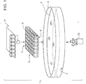
- FIG. 1 is a diagram showing the configuration of the object selecting device 1 of the first embodiment of the present invention.
- the object selecting device 1 of this embodiment includes a container 4 including an inner bottom part 2 and configured to store liquid 3, a plate 9 having a top surface 5 and a bottom surface 6, including through holes 8 at support positions for selection objects 7 and to be immersed in the liquid 3 stored in the container 4, a phase-contrast microscope 10 (determining means) for determining whether or not the objects supported at the support positions are good, and push-out mechanisms 11 (removing means) for removing the object determined to be defective by the phase-contrast microscope 10.
- determining means for determining whether or not the objects supported at the support positions are good
- push-out mechanisms 11 removing means
- the selection objects 7 are objects to be selected from a collection of objects M (see FIG. 3B ) using the object selecting device 1 of this embodiment.
- the type of the collection of objects M is not particularly limited, but examples thereof, include mixtures of particles having various shapes and particle diameters, cell culture solutions and cell treatment solutions containing cells and impurities having various sizes. For example, if the collection of objects M is mixed slurry of particles having various shapes and particles having a predetermined shape are selected using the object selecting device 1, the selected particles having the predetermined shape fall under the selection objects 7. Similarly, if the collection of objects M is a cell culture solution or a cell treatment solution including cells and impurities having various sizes and only cells having a predetermined shape are selected using the object selecting device 1, the selected sells having the predetermined shape fall under the selection objects 7.
- the selection objects are preferably bio-based cells, more preferably bio-based cell aggregates.
- Bio-based cells are objects having relatively large shape deviations. Thus, if the selection objects 7 are bio-based cells, cells having a uniform shape can be selected by using the object selecting device 1 of this embodiment. This can largely contribute to improved operation efficiency in the fields of bio-related technology and medicine.
- the selection objects 7 are bio-based cell aggregates (spheroids)
- a result considering functions of individual cells can be obtained as compared with a test result obtained using one cell since a biosimilar environment considering interactions among cells is reconfigured in the cell aggregate, and experiment conditions can be made uniform in accordance with an environment in a biological body.
- a highly reliable result can be obtained in the fields of bio-related technology and medicine.
- such a cell aggregate is generally formed by aggregating several to several hundred thousands of individual cells.
- cell aggregates vary in size.
- a cell aggregate formed by living cells has a substantially spherical shape.
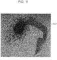
- the cell aggregate may become a cell aggregate AG1 having a distorted shape as shown in FIG. 11 or a cell aggregate AG2 with an uneven density as shown in FIG. 12 .
- the object selecting device 1 of this embodiment only cell aggregates having a shape suitable for a test can be selected from a plurality of cell aggregates having these various shapes.
- the container 4 stores the liquid 3.
- the container 4 is illustrated to be formed of a bottomed cylindrical body including the inner bottom part 2 and having an open upper end.
- the shape of the container 4 is not particularly limited, but the inner bottom part 2 is preferably flat and a relatively flat shape whose height is relatively smaller than a width is preferably adopted in terms of operability, stability and the like.
- the container 4 has only to have such a size sufficient to store the liquid 3 to such an extent that the plate 9 to be described later can be completely immersed.
- the material of the container 4 is not particularly limited, but it is preferable to use a translucent material in terms of possibility to easily confirm a state of a content stored in the container 4. Further, if both the container 4 and the plate 9 are made of a translucent material as described later, operation efficiency can be improved since a user can continuously observe the selection objects 7 using the phase-contrast microscope 10 to be described later from below the container 4.
- the translucent material is not particularly limited, but it is preferable to use, for example, thermoplastic resins, thermosetting resins and photocurable resins. More specifically, the examples of the translucent material include polyethylene resins; polyethylene naphthalate resins; polypropylene resins; polyimide resins; polyvinyl chloride resins; cycloolefin copolymers; norbornene-containing resins; polyether sulfone resins; polyethylene naphthalate resins; cellophanes; aromatic polyamide resins; (meth)acrylic resins such as polymethyl (meth)acrylates; styrene resins such as polystyrenes and styrene-acrylonitrile copolymers; polycarbonate resins; polyester resins; phenoxy resins; butyral resins; polyvinyl alcohols; cellulose-based resins such as ethyl cellulose, cellulose acetate and cellulose acetate butyrate; epoxy resins; phenol resins
- inorganic materials such as metal alkoxides, ceramic precursor polymers, solutions obtained through hydrolysis polymerization of solutions containing metal alkoxides by a sol-gel method, or inorganic materials obtained by solidifying combinations of these such as inorganic materials having a siloxane bond (polydimethylsiloxane, etc.) and glass.
- Soda glass, quartz, borosilicate glass, Pyrex (R) glass, low melting point glass, photosensitive glass and other optical glasses having various refractive indices and Abbe numbers can be widely used as the glass.
- a circular glass dish having a height of several mm to several cm and a diameter of about 10 cm can be used as the container 4 satisfying these conditions.
- the liquid 3 stored in the container 4 is not particularly limited if it does not degrade properties of the selection objects 7, and can be appropriately selected according to the type of the selection objects 7.
- Typical examples of the liquid 3 may include, for example, cell freezing solutions such as glycerol to be added before refrigeration storage and Cell Bankers (produced by Juji Field Inc.), formalin, reagents for fluorescent staining, antibodies, purified water and physiological saline solution in addition to media such as basic media, synthetic media, Eagle's media, RPMI media, Fischer's media, Ham's media, MCDB media and serums.
- the selection objects 7 are cells, a culture preservation solution suited to the cells can be used.
- BxPC-3 human pancreatic tumor cells
- FBS Fetal Bovine Serum
- the amount of the liquid 3 stored in the plate 9 is not particularly limited and is preferably sufficient to completely immerse the plate 9 to be described later.
- the plate 9 is used by being immersed in the liquid 3 stored in the container 4.
- the plate 9 includes through holes 8 at support positions where the selection objects 7 are supported.
- the plate 9 illustrated in FIG. 1 has a flat rectangular parallelepipedic shape having the top surface 5 and the bottom surface 6, and a plurality of through holes 8 penetrating from the top surface 5 to the bottom surface 6 are arranged in a 6x6 matrix, i.e. a total of thirty-six through holes 8 are arranged.
- the shape of the plate 9 is not particularly limited, but is preferably a flat shape because the plate 9 is easily immersed in the container 4 and the selection objects 7 are easily selected from the collection of objects M precipitated right below with gravity when the container 4 has a flat shape and because a microscope is easily focused in observing the objects supported at the support positions of the plate 9.
- the plate 9 has only to have such a size with a width smaller than an opening width of the container 4 and a height smaller than a storage depth of the container 4 since the plate 9 needs to be immersed in the liquid 3 stored in the container 4.
- the material of the plate 9 is not particularly limited, but a translucent material is preferably used because a state of a content can be easily confirmed. Further, as described later, if both the container 4 and the plate 9 are made of a translucent material, the user can continuously observe the selection objects 7 using the phase-contract microscope 10 to be described later from above or below the container 4.
- the translucent material is not particularly limited, but the materials described in the description of the container 4 can be used.
- the plate 9 of this embodiment includes the through holes 8 vertically penetrating through the top surface 5 and the bottom surface 6 of the plate 9 at the support positions for the selection objects 7 as shown in FIGS. 1 and 2.
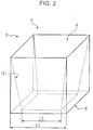
- FIG. 2 is a perspective view showing the through hole 8 of the first embodiment of the present invention.
- the through hole 8 has a tapered portion 12.
- the tapered portion 12 is provided to allow the selection object 7 to precipitate along a direction of gravity and support the selection object 7 in contact with the inner wall surface of the through hole 8 in a state where the plate 9 is immersed in the liquid 3 in the container 4.
- An opening area at an upper end side of the tapered portion 12 is larger than that at a lower end side of the tapered portion 12.
- the tapered portion 12 is so formed that the opening area is gradually narrowed from the top surface 5 toward the bottom surface 6.
- the through holes 8 of the plate 9 capture only the selection objects 7 (selection objects 7c) by the tapered portions 12 and allow non-objects 13 (non-objects 13 c) to pass and precipitate to the inner bottom part 2 of the container 4 as shown in FIGS. 3C and 3D .
- reference sign 7a denotes a selection object precipitating in a direction of gravity A1 and reference sign 13a denotes a non-object precipitating in the direction of gravity A1.
- Reference sign 7b denotes a selection object precipitating in the through hole 8 and reference sign A2 denotes a direction of precipitation of the selection object 7b along the tapered portion 12. Since diameters of the non-objects are smaller than the opening area at the lower ends of the tapered portions 12, the non-objects pass through the through holes 8.
- Reference sign 13b denotes a non-object precipitating in the direction of gravity after passing through the through hole 8. The non-objects 13b having passed through the through holes 8 precipitate to the inner bottom part 2 of the container.
- Reference sign 13c denotes a non-object precipitated on the inner bottom part 2 of the container 4.
- the non-objects having a diameter smaller than the opening area of the lower ends of the tapered portions 12 precipitate to the inner bottom part 2 of the container 4 without being supported by the tapered portions 12 of the through holes 8.
- the selection objects 7a and the non-objects 13a are unlikely to be caught and easily introduced into the through holes 8.
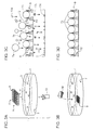
- FIG. 3D is a diagram of the selection objects 7 supported in contact with the tapered portions 12.
- Reference sign 7c denote the supported selection object.
- the number of the through holes 8 is not particularly limited.
- the plate 9 may include only one through hole 8 as shown in FIG. 2 .
- FIG. 2 is also a perspective view showing a modification of the plate 9 of the first embodiment of the present invention.
- a plurality of through holes 8 are preferably arranged because time and labor can be drastically saved and operation efficiency can be improved as compared with the case where the selection objects 7 are individually selected.
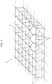
- FIG. 4 is a perspective view showing the plate 9 in which the plurality of through holes 8 are arranged in a matrix.
- the number of the arranged through holes 8 is not particularly limited.
- the plate 9 is illustrated in which a total of thirty six through holes 8 are arranged in a 6 x 6 matrix.
- the shape of the through hole 8 is not particularly limited if the tapered portion 12 is formed as described above and the opening area at the upper end side of the tapered portion 12 is larger than that at the lower end side.
- the through hole 8 preferably has a frustum shape because the selection object 7 is easily inserted into the through hole 8 along the tapered portion 12 and because the substantially spherical selection object 7 is easily selected as compared with the case where the tapered portion 12 is provided only on a part of the inner wall surface of the through hole 8.
- Types of the frustum shape may include truncated cone shapes, truncated pyramid shapes and the like. If the through hole 8 has a truncated pyramid shape, clearances are formed at the corners of the truncated pyramid in a state where the selection object 7 having a substantially spherical shape is supported by the tapered portion 12. As a result, the selection object 7 is not fitted into the through hole 8 and can be easily extracted such as by vertically inverting the plate. Above all, a truncated square pyramid shape and a truncated hexagonal pyramid shape are preferable because of easy processing and easiness to densely form many through holes 8 per unit area of the plate 9.
- a cross-sectional shape of the frustum shape is not particularly limited and may have a cross-sectional shape other than a regular polygonal shape.
- reference sign L1 denotes the length of one side of the opening at the side of the top surface 5 of the through hole 8 when the through hole 8 is formed into a truncated square pyramid shape
- reference sign L2 denotes the length of one side of the opening at the side of the bottom surface 6 of the through hole 8 when the through hole 8 is formed into a truncated square pyramid shape.
- a ratio (L2 2 /L1 2 ) of the opening area at the side of the bottom surface 6 (L2 2 ) to the opening area at the side of the top surface 5 (L1 2 ) is not particularly limited, but is, for example, preferably 0.11 to 0.94, more preferably 0.17 to 0.44 and even more preferably 0.18 to 0.31.
- the plate 9, the supported selection objects 7, the non-object 13d and the push-out mechanisms 11 can be captured within a depth of field of a lens provided in the phase-contrast microscope 10 while the influence of the shadow of the plate 9 on observation is reduced when the non-object 13d is pushed out by a push-out pin 14a of the push-out mechanism 11 (see FIG. 5 ) to be described later while the supported selection objects 7 are observed from above or below the container 4 by the phase-contrast microscope 10.
- the user can easily confirm whether or not the selection objects 7 and the non-object 13d are supported by the plate 9, and the shapes of the supported selection objects 7 and non-object 13d.
- the user can easily confirm the position of the non-object 13d and that of the push-out mechanism 11. Furthermore, even if there is a slight flow of the liquid 3 in the container 4 such as when the collection of objects M is added to the liquid 3, the selection objects 7 supported by the plate 9 are more reliably supported by the plate 9 without being flowed out of the through holes 8 by the flow.
- the phase-contrast microscope 10 (determining means) is provided to observe the shapes of the selection objects 7 supported by the plate 9 from below the container 4. By observing objects using the phase-contrast microscope 10 in this way, the shapes can be clearly recognized and accurately observed, for example, even if the objects are bio-based cells or the like.
- the phase-contrast microscope 10 is adopted as the determining means in this embodiment, the determining means is not particularly limited. Besides general optical microscopes, fluorescence microscopes, polarization microscopes, stereomicroscopes, bright-field microscopes, dark-field microscopes, differential interference microscopes, supersonic microscopes, confocal microscopes, laser scanning microscopes, electronic microscopes, scanning probe microscopes, X-ray microscopes, virtual microscopes, digital microscopes and the like can be used.
- a phase-contrast microscope or a fluorescence microscope is preferably used as the determining means.
- an object needs to be fluorescent.
- the object is measured after being dyed with a fluorescent dye.
- a method for dyeing an object is not particularly limited and a preferable dyeing method may be appropriately adopted.
- chemical fluorescent staining, antibody fluorescent straining or a like method can be adopted.
- GFP green fluorescent protein
- a monitor device (not shown) is attached to the phase-contrast microscope 10.
- the monitor device includes an imaging element for converting an optical image generated by the phase-contrast microscope 10 into an electrical image signal, an image processor for applying image processings such as a gamma correction and a shading correction to the image data, and a display device for displaying image data after the image processings.
- Determination criteria in determining the shape of an object by the phase-contrast microscope 10 are not particularly limited. The determination criteria may be appropriately determined by the user depending on the use application of the selection object 7.
- the push-out mechanisms 11 are provided to remove the non-objects 13 determined to be defective through the image processings and analysis of the obtained image data or the like by the phase-contrast microscope 10 (determining means) by pushing out the non-objects 13 from the support positions of the plate 9.
- FIGS. 5 are diagrams showing a state of operation of the push-out mechanisms 11 of this embodiment.
- the push-out mechanism 11 of this embodiment includes a push-out pin 14a and an actuator 15 for driving the push-out pin 14a to project downward and retract.
- FIG. 5A shows a state where the push-out mechanisms 11 each including the push-out pin 14a and the actuator 15 are arranged above six corresponding through holes 8 in the front row of the plate 9 in a state where objects are supported in the through holes 8 in the front horizontal row of the plate 9 in which a total of thirty six through holes 8 are arranged in a 6x6 matrix.
- Reference sign 13d denotes a supported non-object.
- the actuators 15 are controlled by a drive control mechanism (not shown).
- the actuator 15 is provided to, if it is turned out that the non-object 13d is supported by the tapered portion 12 of the through hole 8 in an observation by the phase-contrast microscope 10, actuate the push-out pin 14a for pushing out such a non-object 13d to project downward and retract.
- the push-out pin 14a is housed in the actuator 15 and pushed out in response to a push-out command from the drive control mechanism.
- the user causes the push-out pin 14a of the actuator 15a provided above the support position for the non-object 13d out of the actuators 15 controlled by the above drive control mechanism to project and push out the non-object 13d out of the through hole 8 when observing the objects supported at the support positions of the plate 9 using the above phase-contrast microscope 10 and finding out the object (non-object 13d) not having a predetermined shape.
- the non-object 13d has a distorted shape as compared with the selection objects 7 and does not have the predetermined shape.
- the user causes the push-out pin 14a to project from the actuator 15 (actuator 15a) at that position to push out the non-object 13 by controlling the operation of the actuator 15 via the drive control mechanism.
- Reference sign 13e denotes the pushed-out non-object
- reference sign 14b denotes the pushed-out push-out pin
- an arrow A3 indicates a direction of projection of the push-out pin.
- the push-out pin 14a is controlled by the actuator 15.
- the push-out pin 14a is provided to push out the non-object 13 supported in the through hole 8 through an opening at the lower end side of the tapered portion 12 (see FIG. 4 ) of the through hole 8.
- the length of the push-out pin 14a is not particularly limited, but is preferably a length capable of sufficiently pushing out the non-object 13d supported in the through hole 8.
- the shape of the push-out pin 14a is not particularly limited, but is preferably such a shape as to be vertically movable in the actuator 15 and have a large contact area with the non-object 13d because of easiness to push out the non-object 13d in pushing out the non-object 13d supported in the through hole 8.
- the push-out pin 14a preferably has a cylindrical shape, a prism shape or a shape with at least a flat tip part.
- FIG. 5C is a diagram showing another example of the push-out pin 14a of this embodiment.
- a push-out jig 14c shaped to be suitable for pressing a non-object supported by the plate 9 is mounted on the tip of the push-out pin 14a.
- a projection provided on the push-out jig 14c presses and pushes out the non-object 13e in a state pushed out from the actuator 15.
- the shape of the push-out jig 14c is not particularly limited and may be a conical shape in conformity with the shape of the tapered portion of the through hole 8 besides the shape of the projection.
- the push-out jig 14c may be integrally formed to the push-out pin 14a or may be joined with the push-out pin 14a to be integral to the push-out pin 14a after being formed as a different body.
- FIGS. 5A and 5B six push-out mechanisms 11 arranged side by side in the front horizontal row are shown in FIGS. 5A and 5B .
- the plate 9 or the push-out mechanisms 11 or both of them may be appropriately moved in the case of pushing out non-objects 13d supported in six through holes 8 in the second row from the front side of the plate 9.
- a total of thirty six actuators 15 and a total of thirty six push-out pins 14a may be arranged in a 6x6 matrix above the plate 9 in accordance with the arrangement of the through holes 8 of the plate 9. In such a case, the plate 9 or the push-out mechanisms 11 need not be moved as described above and operation efficiency can be improved.
- phase-contrast microscope 10 and the push-out mechanisms 11 can be connected by an externally provided control mechanism (not shown). This enables the user to determine the objects using the phase-contrast microscope 10 and transmit position information of the non-object 13d determined to be defective to the control mechanism.
- the control mechanism having received the position information transmits this position information to the push-out mechanism and causes the push-out mechanism to operate at an appropriate timing.
- the object selecting device 1 of this embodiment only the selection objects 7 having the predetermined shape out of the collection of objects M having different shapes can be supported in the tapered portions 12 and the non-objects 13 other than the selection objects 7 can be allowed to precipitate to the inner bottom part 2 of the container 4. Further, even if the non-object 13d is supported in the tapered portion 12, the position can be confirmed through an observation by the phase-contrast microscope 10 and the non-object 13d can be pushed out and removed by the push-out mechanism 11 including the push-out pin 14a. Thus, only the selection objects 7 can be supported by the plate 9. The supported selection objects 7 need not be extracted such as by suction while causing forced deformation or the like.
- the selection objects 7 can be extracted by a gentle method such as collection by vertically inverting the plate 9 and suction using a suction device (not shown) with a suction tip having a suction port sufficiently larger than diameters of the selection objects 7 in such a manner as not to apply a load to the selection objects 7. Therefore, only the selection objects 7 having the predetermined shape can be selected without being deformed or destroyed.
- a process performed by the user in this embodiment can be automatically performed using a robot by controlling the robot by software programming the content of the process in advance.
- the selection objects 7 are cell aggregates and can be gently extracted such as by vertically inverting the plate 9 after being supported by the plate 9 in this embodiment, the selection objects 7 may be kept for a predetermined time at the support positions of the plate 9 if necessary. For example, if the selection objects 7 are not sufficiently grown cell aggregates, but single cells or undergrown cell aggregates, the user can continue to cultivate these selection objects 7 kept supported at the support positions of the plate 9 and extract these selection objects 7 after the selection objects 7 have sufficiently grown.
- the extracted cell aggregates can be subjected to various screening.
- the vertically penetrating through holes 8 are formed at the support positions of the plate 9 of this embodiment.
- a culture solution can be sufficiently brought into contact with undergrown cells supported at the support positions of the plate 9.
- the plate 9 can preliminarily select undergrown cells before being sufficiently grown and form sufficiently grown cell aggregates by cultivating the undergrown cells at the support positions.
- FIG. 6 is a diagram showing a state of operation of injection nozzles 16 of the second embodiment of the present invention.
- the object selecting device of the second embodiment is similar to the object selecting device 1 of the first embodiment except for including the injection nozzles 16 from which a push-out mechanism 11A (removing means, push-out means) can inject an injection liquid as shown in FIG. 6 . Thus, only points of difference are described.
- the push-out mechanism 11A including six injection nozzles 16 arranged in a row is illustrated in this embodiment.
- Each injection nozzle 16 is so provided that a nozzle tip thereof is arranged above a corresponding through hole 8 in the front row of the plate 9.
- the injection nozzles 16 are controlled by a drive control mechanism (not shown). If it is found out that a non-object 13d is supported in a tapered portion 12 of the through hole 8 in an observation by the phase-contrast microscope 10 described above, the injection nozzle 16 injects an injection liquid 17 for pushing out the non-object 13d.
- the injection nozzles 16 receive the supply of the injection liquid 17 from an externally provided injection liquid supply source (not shown).
- a user causes the injection nozzle 16a provided to correspond to a support position of a non-object 13d out of the injection nozzles 16 controlled by the above drive control mechanism to inject the injection liquid 17 to push out the non-object 13d from the through hole 8 when observing objects supported at support positions of the plate 9 using the phase-contrast microscope 10 and finding out the object not having a predetermined shape (non-object 13d).
- a user causes the injection nozzle 16a provided to correspond to a support position of a non-object 13d out of the injection nozzles 16 controlled by the above drive control mechanism to inject the injection liquid 17 to push out the non-object 13d from the through hole 8 when observing objects supported at support positions of the plate 9 using the phase-contrast microscope 10 and finding out the object not having a predetermined shape (non-object 13d).
- the user causes the injection liquid 17 to be injected from the injection nozzle (injection nozzle 16a) at that position to push out the non-object 13d by controlling the operation of the injection nozzle 16 via the drive control mechanism.
- An arrow A4 indicates a direction of injection of the injection liquid 17.
- the shape of the nozzle tip of the injection nozzle 16 is narrowed so as to be able to inject the injection liquid 17 only to the non-object 13d and a distance between the injection nozzle 16 and the through hole 8 is so adjusted that the injection liquid is not injected to the selection objects 7 supported in the adjacent through holes 8.
- the injection liquid 17 is supplied from the injection liquid supply source in this embodiment, it is preferable to provide a circulation mechanism for circulating liquid 3 stored in a container 4 to the injection nozzles 16 in the case of using the liquid 3 stored in the container 4 as the injection liquid 17. In this case, the amount of the liquid 3 stored in the container 4 is neither increased nor decreased by the injection of the injection liquid 17 by the injection nozzles 16. Further, the liquid 3 is not diluted by the injection liquid 17.
- the injection liquid 17 to be injected may be something other than the liquid 3 stored in the container 4 and can be appropriately selected within such a range as not to adversely affect properties of the selection objects 7.
- gas such as air may be injected as injection gas instead of the injection liquid 17. In this case, gas which does not adversely affect the properties of the selection objects 7 can be appropriately selected as the injection gas.
- the non-object 13d can be pushed out by injecting the injection liquid.
- the non-object 13d is pushed out such as by a push-out pin, there is no possibility of damaging the plate 9 since there is no contact of the push-out pin with a part of the plate 9 in removing the non-object 13d.
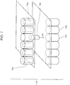
- FIG. 7 is a diagram showing a state of operation of a push-out mechanism 11B of the third embodiment of the present invention.
- the object selecting device of the third embodiment is similar to the object selecting device 1 of the first embodiment except that the push-out mechanism 11B (removing means, push-out means) drives push-out pins 19a by electromagnets as shown in FIG. 7 . Thus, only points of difference are described.
- the push-out mechanism 11B of this embodiment includes the push-out pins 19a, upper actuators 18a each with the push-out pin 19a, and lower actuators 18b each with the electromagnet for causing the push-out pin 19a to project.
- the illustrated push-out mechanism 11b six upper actuators 18a and six lower actuators 18b are arranged in a row and vertically face each other.
- the arrangements of the upper actuators 18a and the push-out pins 19a are similar to those of the actuators 15 and the push-out pins 14a of the first embodiment.
- the lower actuators 18b are provided below a plate 9, and provided on an outer bottom part of a container 4 when the plate 9 is placed on an inner bottom part 2 of the container 4.
- a user causes the push-out pin 19a included in the upper actuator 18a provided to correspond to a position where a non-object is supported out of the upper actuators 18a to project and push out the non-object 13 from a through hole by energizing the electromagnet controlled by a drive control mechanism when observing objects supported at support positions of the plate 9 using the phase-contrast microscope 10 described above and finding out the object not having a predetermined shape (non-object).
- the push-out pins 19a are housed in the upper actuators 18a. In a state where the electromagnets of the lower actuators are not energized (lower actuators 18b), the push-out pins 19a remain housed in the upper actuators 18a.
- the push-out pin 19a projects from the upper actuator 18a, thereby allowing the non-object to precipitate to the inner bottom part of the container through an opening at the lower end of a tapered portion 12.
- An arrow A5 indicates a direction of projection of the push-out pin 19a.
- the positions of actuators each with an electromagnet are not particularly limited.
- actuators each with an electromagnet are provided further above the upper actuators 18a and energized in a direction opposite to a direction of energization to the electromagnets of the lower actuators 18b, the push-out pins 19a can be pushed out from the upper actuators 18a.
- an elastic member such as a coiled compression spring may be provided in each upper actuator 18a and the push-out pin 19a may be controlled to project and retract.
- the user can control the push-out pin 19a in such a manner that the push-out pin 19a is held in the upper actuator 18a while compressing the compression spring, for example, by energizing the electromagnet.
- the user can cause the push-out pin 19a to be pushed out from the upper actuator 18a utilizing an elastic force of the compression spring by stopping energization to the electromagnet only in pushing out the push-out pin 19a from the upper actuator 18a.
- FIG. 8 is a diagram showing a state of operation of a pull-out mechanism 11 C (removing means, pull-out means) of the fourth embodiment of the present invention.
- the object selecting device of the fourth embodiment is as in the first embodiment except that the pull-out mechanism 11C including suction nozzles 20a is provided as a removing means on the side of a bottom surface 6 of a plate 9 as shown in FIG. 8 . Thus, only points of difference are described.
- the suction nozzle 20a is provided near an opening at a lower end side of a tapered portion of each through hole 8.
- the suction nozzles 20a are arranged in a row below the plate 9 and correspond to the respective through holes 8.
- the suction nozzles 20a are nozzles for sucking objects supported in the tapered portions.
- reference sign 20a denotes the suction nozzle in a non-suction state
- reference sign 20b denotes the suction nozzle in a suction state
- reference sign 13f denotes a sucked non-object 13.
- the suction nozzle 20a includes a valve mechanism (not shown) controlled by a drive control mechanism (not shown), and is connected to an externally provided suction device (not shown) via the valve mechanism. If it is found out that the non-object 13f is supported in the tapered portion of the through hole 8 in an observation by the phase-contrast microscope 10 described above, the user drives the external suction device and the drive control mechanism to open only the valve mechanism of the corresponding suction nozzle 20a, thereby sucking the non-object 13f to pull out and remove the non-object 13f from the through hole 8.
- An arrow A6 indicates a direction of pulling out the non-object 13f by the suction nozzle 20b.
- the tip of the suction nozzle 20a is provided at a position sufficiently close to the corresponding through hole 8 so as not to erroneously pull out selection objects 7 supported in the tapered portions of the adjacent through holes 8.
- the non-object 13f can be pulled out and removed, there is no contact with a part of the plate in removing the non-object 13f as compared with the case where the non-object 13f is pushed out such as by a push-out pin. Thus, there is no possibility of damaging the plate. Further, if a position where the plate is to be placed is determined in the container, the pull-out mechanism 11C including the suction nozzles 20a has only to be provided at a position corresponding to the plate to be placed, wherefore operation efficiency can be drastically improved.
- suction nozzles 20a are arranged in a row below the plate 9 in this embodiment, the number of the arranged suction nozzles 20a is not particularly limited. One suction nozzle 20a may be arranged or a plurality of suction nozzles 20a may be arranged in a row. Suction nozzles 20a may be, for example, arranged in a 6x6 matrix in accordance with the positions of the through holes 8.
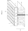
- FIG. 9 is a diagram showing a state of operation of a modification of the pull-out mechanism 11C (pull-out mechanism 11D) of this embodiment.
- suction nozzles 20b arranged above are connected to an externally provided suction device (not shown) and suck the non-object 13f by operating the suction device and generating a suction force at a suction port of the suction nozzle 20b.
- An arrow A5 indicates a direction of sucking the non-object 13f by the suction nozzle 20b. The pulled-out non-object 13f is sucked by the suction nozzle 20b and discarded to a disposal space connected to an inner passage in the suction nozzle 20b through the inner passage.
- the object selecting method of this embodiment is an object selecting method for selecting selection objects from a collection of objects including the selection objects, and includes an immersion step, a precipitation step, an arrangement step, a determination step and a removal step. Each step is described below.
- the immersion step is a step of immersing a plate having a top surface and a bottom surface and configured to support selection objects in a container including an inner bottom part and storing liquid.
- the container and the plate are not described since being the same as those described in detail in the description of the object selecting device 1 of the first embodiment.
- FIG. 3A is a diagram of the plate 9 to be immersed into the container 4 storing the liquid 3.
- the plate 9 is immersed into the liquid 3 in advance in a state where nothing is supported at the support positions. This enables the user to select the selection objects 7 in the liquid 3 and prevent the selection objects 7 included in the collection of objects M (see FIG. 3B ) such as a cell culture solution from being exposed to outside air and being dried.
- the precipitation step is a step of adding the collection of objects including the selection objects to the liquid from a side of the top surface of the plate and causing the collection of objects to precipitate along the direction of gravity into through holes formed in the plate, arranged at support positions where the selection objects are supported and including tapered portions on the inner wall surfaces thereof, the opening area at the upper ends of the tapered portions being larger than that at the lower ends of the tapered portions.
- the arrangement step is a step of bringing the selection objects out of the collection of objects precipitating in the through holes into contact with the tapered portions and supporting them at the support positions.
- FIGS. 3B to 3D are diagrams showing a procedure of selecting the selection objects 7 in the object selecting device 1.
- FIG. 3B is a diagram showing a state where the collection of objects M including the selection objects 7 is added to the liquid 3 from the side of the top surface of the plate 9.
- a method for adding the collection of objects M is not particularly limited, but the collection of objects M is preferably gently added from a position close to the liquid level or directly added to the liquid 3 using a pipette or the like when being added to the liquid 3 in order to eliminate the drying of the selection objects 7 and a physical impact.
- the collection of objects M added to the liquid 3 gently precipitates with gravity while being dispersed in the liquid 3. Thus, a physical impact on the selection objects 7 is reduced.
- FIG. 3C is a diagram showing a state where the collection of objects M added to the liquid 3 precipitates in a plurality of arranged through holes 8 of the plate 9 along the direction of gravity.
- the selection objects 7 and the non-objects 13 in contact with the tapered portions 12 are introduced into the through holes 8 while descending along the tapered portions 12.
- the non-objects 13 Since the diameters of the non-objects 13 are smaller than the opening area at the lower ends of the tapered portions 12, the non-objects 13 pass through the through holes 8. The non-objects 13 having passed through the through holes (non-objects 13b) precipitate to the inner bottom part 2 of the container.
- the objects (selection objects 7c) having larger diameters than the opening area at the lower ends of the tapered portions 12 out of the collection of objects M precipitating into the through holes 8 are supported by the tapered portions 12 in contact with the inner wall surfaces of the tapered portions 12 and the through holes 8 and arranged at the support positions of the plate 9.
- the determination step is a step of determining whether or not the objects supported at the support positions of the plate through the precipitation step and the arrangement step have a predetermined shape.
- a determination method is not particularly limited, and a method for observation using the phase-contrast microscope (determining means) described above or the like can be adopted.
- the objects determined to be defective (non-objects) in this determination step are removed by a removing means such as the push-out mechanism in the removal step to be described next.
- the removal step is a step of removing the objects determined to be defective in the determination step by the push-out mechanism (removing means).
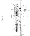
- FIG. 10 is a diagram showing each step of the object selecting method of this embodiment.
- a container 41 divided into two chambers is used.
- the selection objects 7 described above are selected and the objects having different diameters are selected and removed.
- a state of selection is obtained mainly by observing the presence or absence of the objects supported by the plate 9 by the phase-contrast microscope 10 (determining means) provided above or below the container 41.
- the non-objects 13 having diameters smaller than the opening area at the lower ends of the tapered portions are removed and the selection objects 7 are selected in the tapered portions.
- the plate 9 is moved to an adjacent cell selection chamber C2 and further selection proceeds based on the shape.
- the shapes of the objects supported by the plate 9 are observed by the phase-contrast microscope 10 provided above or below the container.
- the fluorescence microscope described above or the like can be adopted as the determining means.
- the phase-contrast microscope 10 is used by being appropriately moved from a position of observation in the cell capture chamber C1, but the phase-contrast microscopes 10 corresponding to the respective chambers may be prepared. Further, the position of the phase-contrast microscope 10 may be fixed and the container 41 may be moved.
- phase-contrast microscope 10 As the determining means, objects which are substantially transparent can be clearly observed. Further, if the selection objects 7 are dyed with a fluorescent dye such as trypan blue, they can be observed by the fluorescence microscope.
- the user observes the objects supported in the tapered portions of the plate using the phase-contrast microscope 10. As a result, if the object has a diameter larger than a predetermined diameter or a distorted shape other than the predetermined shape or is a defective cell aggregate including dead cells, the user can newly determine this object as the defective non-object 13.
- the non-object 13 determined to be defective is removed by the push-out mechanism 11 (removing means, push-out means) described above.
- the selection objects 7 are collected by a gentle method such as by vertically inverting the plate 9 or by sucking the selection objects 7 in such a manner as not to apply a load to the selection objects 7 using a suction device (not shown) with a suction tip including a suction port sufficiently larger than the diameters of the selection objects 7.
- the removing method is not particularly limited. Removing methods using various removal mechanisms (removers) can be adopted as well as the push-out mechanisms and the pull-out mechanisms shown in the second to fourth embodiments.
- the user can also adopt a method for removing the non-object 13 by irradiating laser light.
- the user can remove the non-object 13 by confirming the position of the non-object 13 supported by the plate 9 using the phase-contrast microscope 10 or the like and fracturing the non-object 13 by irradiating laser light to the non-object 13 or causing apoptosis or necrosis.
- An ultraviolet laser having a wavelength of 350 nm or a green semiconductor laser having a wavelength of 532 nm can be, for example, used as the laser light to be irradiated.
- the object selecting method of this embodiment it is possible to support only the selection objects having the predetermined shape out of the collection of objects having different shapes by the plate and allow the non-objects having smaller particle diameters than the predetermined shape to precipitate to the inner bottom part of the container. Further, whether or not the non-object having a distorted shape is included in the objects supported by the plate can be determined by the determining means and, if such a non-object is present, it can be removed by the removing means. As a result, only the selection objects can be supported by the plate. Since the supported selection objects need not be extracted such as by suction while causing forced deformation or the like and applying a load to the objects, they can be gently extracted such as by a method of vertically inverting the plate. Thus, only the selection objects having the predetermined shape can be selected without being deformed or destroyed.
- An object selecting device is an object selecting device as described above.
- the selection object having a predetermined shape out of the collection of objects having different shapes is supported by the plate and non-objects having smaller particle diameters than the predetermined shape are allowed to precipitate to the inner bottom part of the container. Further, whether or not any non-object having a distorted shape is included in the objects supported by the plate is determined by the determining means. If such a non-object is present, it can be removed by the removing means. As a result, only the selection object can be supported by the plate.
- the supported selection object needs not be extracted such as by suction while causing forced deformation or the like, it can be gently extracted by a method such as collection by vertically inverting the plate or suction in such a manner as not to apply a load to the selection object using a suction device with a suction tip including a suction port sufficiently larger than a diameter of the selection object.
- a method such as collection by vertically inverting the plate or suction in such a manner as not to apply a load to the selection object using a suction device with a suction tip including a suction port sufficiently larger than a diameter of the selection object.
- the through hole includes a tapered portion which allows the selection object to precipitate along a direction of gravity and supports the selection object by bringing the selection object into contact with the inner wall surface of the through hole in a state where the plate is immersed in the liquid in the container, and an opening area at the upper end of the tapered portion is larger than an opening area at the lower end of the tapered portion.
- the collection of objects added from above the plate is easily introduced into the through hole via the tapered portion when reaching the top surface of the plate.
- the through hole preferably has a frustum shape.
- the selection object is easily introduced into the through hole since the inner side surface of the through hole serves as the inclined tapered portion. Further, the selection object having a substantially spherical shape is easily selected, for example, as compared with the case where the tapered portion is provided on a part of the inner wall surface of the through hole.
- the plate preferably includes a plurality of the arranged through holes.
- selection objects having a plurality of predetermined shapes can be simultaneously selected and labor and time can be drastically saved and operation efficiency can be improved as compared with the case of individually selecting the selection objects.
- a plurality of nozzles are prepared in correspondence with the arrangement of the through holes, for example, in the case of extracting the selection objects by nozzles or the like, it can contribute to the automation of the device. Note that the plurality of nozzles can be moved in accordance with the arrangement of the through holes.
- the plate preferably includes a plurality of the through holes arranged in a matrix.
- selection objects can be simultaneously selected.
- selection objects can be subjected to high-throughput screening and the like and a work amount can be drastically reduced.
- the container and the plate are preferably made of a translucent material.
- the selection objects can be continuously confirmed such as by a microscope from above or below the container and operation efficiency can be improved.
- the determining means is preferably a phase-contrast microscope.
- the shape can be clearly recognized and accurate selection can be made.
- the collection of objects is dyed with a fluorescent dye and the determining means is a fluorescence microscope.
- the shape can be clearly recognized and accurate selection can be made.
- the removing means is preferably a push-out means for removing the object determined to be defective by the determining means by pushing out the object from the through hole.
- the non-object supported by the plate can be reliably caused to drop to the inner bottom part of the container. Further, since the non-object is pushed out from the upper end side to the lower end side of the tapered portion, it can be pushed out while being observed by the determining means, wherefore operation efficiency is improved.
- the removing means is preferably a pull-out means for removing the object determined to be defective by the determining means by pulling out the object from the through hole.
- the object can be removed by being sucked together with the surrounding liquid.
- a possibility that a part of the non-object remains without being removed is reduced and removal efficiency can be improved.
- the selection object is preferably a bio-based cell.
- the present invention can be applied to the bio-based cell, which is an object with a large shape deviation, and can provide a device capable of contributing to an improvement in operation efficiency in the fields of bio-related technology and medicine.
- the selection object is preferably a bio-related cell aggregate.
- the bio-based cell aggregate can provide a result considering functions of individual cells as compared with a test result obtained using one cell since a biosimilar environment considering interactions among cells is reconfigured in the cell aggregate, and experiment conditions can be made uniform in accordance with an environment in a biological body.
- the present invention can provide a device capable of obtaining a highly reliable result in the fields of bio-related technology and medicine.
- An object selecting method according to another aspect of the present invention is an object selecting method as described above.
- the selection object having a predetermined shape out of the collection of objects having different shapes is supported by the plate and non-objects having smaller particle diameters than the predetermined shape are allowed to precipitate to the inner bottom part of the container. Further, whether or not any non-object having a distorted shape is included in the objects supported by the plate is determined by the determiner. If such a non-object is present, it can be removed by the remover. As a result, only the selection object can be supported by the plate. Since the supported selection object needs not be extracted such as by suction while causing forced deformation or the like, it can be gently extracted by a method such as collection by vertically inverting the plate. Thus, only the selection object having the predetermined shape can be selected without being deformed or destroyed.
Landscapes
- Health & Medical Sciences (AREA)
- Chemical & Material Sciences (AREA)
- Life Sciences & Earth Sciences (AREA)
- Engineering & Computer Science (AREA)
- Bioinformatics & Cheminformatics (AREA)
- General Health & Medical Sciences (AREA)
- Wood Science & Technology (AREA)
- Zoology (AREA)
- Organic Chemistry (AREA)
- Biotechnology (AREA)
- Biochemistry (AREA)
- Physics & Mathematics (AREA)
- Analytical Chemistry (AREA)
- General Physics & Mathematics (AREA)
- General Engineering & Computer Science (AREA)
- Microbiology (AREA)
- Genetics & Genomics (AREA)
- Sustainable Development (AREA)
- Biomedical Technology (AREA)
- Nuclear Medicine, Radiotherapy & Molecular Imaging (AREA)
- Pathology (AREA)
- Immunology (AREA)
- Cell Biology (AREA)
- Medicinal Chemistry (AREA)
- Molecular Biology (AREA)
- Hematology (AREA)
- Fluid Mechanics (AREA)
- Dispersion Chemistry (AREA)
- Optics & Photonics (AREA)
- Clinical Laboratory Science (AREA)
- Chemical Kinetics & Catalysis (AREA)
- Apparatus Associated With Microorganisms And Enzymes (AREA)
- Sampling And Sample Adjustment (AREA)
Claims (7)
- Objektauswahlvorrichtung (1) zum Auswählen eines Auswahlobjektes (7) aus einer Sammlung von Objekten, das Auswahlobjekt (7) einschließend, umfassend:einen Behälter (4), einschließend ein inneres Unterteil (2) und gestaltet, um Flüssigkeit (3) aufzubewahren;eine Platte (9) mit einer oberen Oberfläche (5) und einer unteren Oberfläche (6), einschließend eine Mehrzahl von Durchgangslöchern (8) an einer Trageposition für das Auswahlobjekt (7), wobei jedes der Durchgangslöcher (8) von der oberen Oberfläche (5) zu der unteren Oberfläche (6) durchgeht, und um in die Flüssigkeit (3), aufbewahrt in dem Behälter (4), eingetaucht zu werden;ein Bestimmungsmittel (10), angeordnet unter dem Behälter (4) und einschließend ein Mikroskop zur Beobachtung von unterhalb des Behälters (4), ob das Objekt, getragen an der Trageposition, gewünscht ist oder nicht; undein Entfernungsmittel (11), angeordnet über dem Behälter (4) und gestaltet, um das Objekt, das von dem Bestimmungsmittel (10) als schadhaft bestimmt ist, zu entfernen und nur das Auswahlobjekt (7) in einem Zustand, getragen an der Trageposition, zurückzulassen, dadurch gekennzeichnet, dass;das Durchgangsloch (8) konische Wände, die spitze Bereiche zwischen konischen Bereichen (12) des Durchgangslochs (8) bilden, einschließt, so dass, wenn ein Objekt, eingetaucht in eine Flüssigkeit, sich durch Schwerkraft absetzt, es mit der inneren Wandoberfläche des Durchgangslochs (8) in Kontakt gebracht wird, und ein Öffnungsbereich an dem oberen Ende des konischen Bereichs größer ist als ein Öffnungsbereich am unteren Ende des konischen Bereichs (12),das Bestimmungsmittel (10) die Objekte, getragen an der Trageposition, beobachtet, wobei die getragenen Objekte eine Größe aufweisen, die es erlaubt, in das Durchgangsloch (8) von den oberen Enden der konischen Bereiche (12) eingebracht zu werden, während sie es nicht erlaubt, durch die unteren Enden der konischen Bereiche (12) zu gelangen, um zu bestimmen, ob die Objekte gewünscht sind oder nicht, unddas Entfernungsmittel (11) die Objekte, die von dem Bestimmungsmittel (10) als schadhaft bestimmt wurden, aus den Objekten, getragen von der inneren Wandfläche (12), entfernt.
- Objektauswahlvorrichtung (1) nach Anspruch 1, wobei der Behälter (4) und die Platte (9) aus einem lichtdurchlässigen Material hergestellt sind.
- Objektauswahlvorrichtung (1) nach Anspruch 1 oder 2, wobei das Mikroskop ein Phasenkontrastmikroskop ist.
- Objektauswahlvorrichtung (1) nach einem der Ansprüche 1 bis 3, wobei die Sammlung von Objekten mit einem Fluoreszenzfarbstoff gefärbt ist und das Mikroskop ein Fluoreszenzmikroskop ist.
- Objektauswahlvorrichtung (1) nach einem der Ansprüche 1 bis 4, wobei das Auswahlobjekt (7) eine bio-basierte Zelle ist.
- Objektauswahlvorrichtung (1) nach Anspruch 5, wobei das Auswahlobjekt (7) ein bio-bezogenes Zellaggregat ist.
- Objektauswahlverfahren zur Auswahl eines Auswahlobjektes (7) von einer Sammlung von Objekten, einschließend das Auswahlobjekt (7), durch Verwenden der Objektauswahlvorrichtung (1) nach einem der Ansprüche 1 bis 6, umfassend:einen Eintauchschritt des Eintauchens der Platte (9) in den Flüssigkeit (3) aufbewahrenden Behälter (4);einen Absetzschritt des Zugebens einer Sammlung von Objekten, einschließend das Auswahlobjekt (7), zu der Flüssigkeit (3) von einer Seite der oberen Oberfläche (5) der Platte (9) und des Veranlassens des Absetzens der Sammlung von Objekten entlang einer Schwerkrafts-Richtung in das Durchgangsloch (8);einen Anordnungsschritt des Tragens von Objekten mit einer Größe, die es erlaubt, in das Durchgangsloch (8) von den oberen Enden der konischen Bereiche (12) eingebracht zu werden, während sie es nicht erlaubt, durch die unteren Enden der konischen Bereiche (12) aus der Sammlung von Objekten, abgesetzt in dem Durchgangsloch (8) an der Trageposition, zu gelangen;einen Bestimmungsschritt des Bestimmens von unterhalb des Behälters (4) durch ein Mikroskop, eingeschlossen in einem Bestimmungsmittel (10), ob das Objekt, getragen an der Trageposition gewünscht ist oder nicht; undeinen Entfernungsschritt des Entfernens des durch das Bestimmungsmittel (10) als schadhaft erkannten Objekts durch ein Entfernungsmittel (11), angeordnet über dem Behälter (4), und des ausschließlichen Zurücklassens des Auswahlobjekts (7) in einem Zustand, getragen an der inneren Wandoberfläche, von den Objekten, getragen an der Trageposition.
Applications Claiming Priority (1)
| Application Number | Priority Date | Filing Date | Title |
|---|---|---|---|
| PCT/JP2011/007115 WO2013093961A1 (ja) | 2011-12-20 | 2011-12-20 | 対象物選別装置および対象物選別方法 |
Publications (3)
| Publication Number | Publication Date |
|---|---|
| EP2796538A1 EP2796538A1 (de) | 2014-10-29 |
| EP2796538A4 EP2796538A4 (de) | 2015-01-14 |
| EP2796538B1 true EP2796538B1 (de) | 2017-04-19 |
Family
ID=48667893
Family Applications (1)
| Application Number | Title | Priority Date | Filing Date |
|---|---|---|---|
| EP11878294.5A Active EP2796538B1 (de) | 2011-12-20 | 2011-12-20 | Objektauswahlvorrichtung und verfahren zur objektauswahl |
Country Status (6)
| Country | Link |
|---|---|
| US (1) | US20140341680A1 (de) |
| EP (1) | EP2796538B1 (de) |
| JP (1) | JP5827696B2 (de) |
| KR (1) | KR101654668B1 (de) |
| CN (1) | CN104011196B (de) |
| WO (1) | WO2013093961A1 (de) |
Families Citing this family (13)
| Publication number | Priority date | Publication date | Assignee | Title |
|---|---|---|---|---|
| WO2013093954A1 (ja) * | 2011-12-19 | 2013-06-27 | ヤマハ発動機株式会社 | 対象物選別装置および対象物選別方法 |
| JP5827696B2 (ja) * | 2011-12-20 | 2015-12-02 | ヤマハ発動機株式会社 | 対象物選別装置および対象物選別方法 |
| WO2015079477A1 (ja) * | 2013-11-29 | 2015-06-04 | ヤマハ発動機株式会社 | 吸引方法 |
| JP6279743B2 (ja) * | 2014-08-05 | 2018-02-14 | ヤマハ発動機株式会社 | 対象物の保持装置 |
| US10138452B2 (en) | 2014-08-05 | 2018-11-27 | Yamaha Hatsudoki Kabushiki Kaisha | Object-holding device |
| WO2017061528A1 (ja) * | 2015-10-09 | 2017-04-13 | 国立大学法人名古屋大学 | 血小板製造用デバイス、血小板製造装置及び血小板製造方法 |
| US10850627B2 (en) | 2015-12-04 | 2020-12-01 | Cyberswitchingpatents, Llc | Electric vehicle charging system |
| US10843581B2 (en) | 2015-12-04 | 2020-11-24 | Cyberswitchingpatents, Llc | Electric vehicle charging method |
| US11180034B2 (en) | 2015-12-04 | 2021-11-23 | Cyberswitchingpatents, Llc | Electric vehicle charging system with priority charging |
| US11104246B2 (en) | 2015-12-04 | 2021-08-31 | Cyber Switching Solutions, Inc. | Electric vehicle charging system interface |
| JP7493945B2 (ja) * | 2020-01-28 | 2024-06-03 | ポーラ化成工業株式会社 | 培養組織の観察方法、培養方法、評価方法及び培養器具 |
| US20230203422A1 (en) * | 2020-05-28 | 2023-06-29 | Toyo Seikan Group Holdings, Ltd. | System for culturing cells including removing air in cell culture bag |
| EP4351972A4 (de) * | 2021-06-07 | 2025-04-30 | Plexium, Inc. | Transferspender für testvorrichtungen mit perlengrössenausschluss |
Family Cites Families (12)
| Publication number | Priority date | Publication date | Assignee | Title |
|---|---|---|---|---|
| JPH05103658A (ja) | 1991-09-30 | 1993-04-27 | Shimadzu Corp | カプセルの選別装置 |
| FR2754270B1 (fr) * | 1996-10-07 | 1998-12-24 | Goemar Lab Sa | Genes codant pour des iota-carraghenases et leur utilisation pour la production d'enzymes de biodegradation des carraghenanes |
| US20060128006A1 (en) * | 1999-11-10 | 2006-06-15 | Gerhardt Antimony L | Hydrodynamic capture and release mechanisms for particle manipulation |
| CA2311622A1 (en) * | 2000-06-15 | 2001-12-15 | Moussa Hoummady | Sub-nanoliter liquid drop dispensing system and method therefor |
| JP4361271B2 (ja) * | 2000-10-10 | 2009-11-11 | バイオトローブ・インコーポレイテツド | アッセイ、合成、および保存用の器具、ならびに、その作製、使用、および操作の方法 |
| GB0321158D0 (en) * | 2003-09-10 | 2003-10-08 | Central Research Lab Ltd | Apparatus and method for handling cells,embryos or oocytes |
| JP4731556B2 (ja) * | 2004-07-02 | 2011-07-27 | サイトリ セラピューティクス インコーポレイテッド | 臨床的に安全な脂肪組織由来再生細胞を単離し、使用するためのシステムおよび方法 |
| EP1920045A4 (de) | 2005-08-11 | 2011-07-06 | Life Technologies Corp | Vorrichtung für test, synthese und lagerung sowie verfahren zur herstellung, verwendung und manipulation davon |
| EP2536819B1 (de) * | 2010-02-16 | 2024-12-18 | The University of North Carolina at Chapel Hill | Array von mikrogeformten strukturen zum sammeln oder kultivieren von zellen |
| KR20130055591A (ko) * | 2010-04-13 | 2013-05-28 | 가부시키가이샤 르네상스 에너지 인베스트먼트 | 암 조직 유래 세포괴 또는 암 세포 응집괴로부터 얻어지는 암 치료용 조성물과 그것을 이용한 면역요법제의 제조 방법 및 면역요법 효과 평가 방법 |
| KR20130024904A (ko) * | 2010-05-26 | 2013-03-08 | 지방독립 행정법인 오사카 부립 병원 기구 | 암 조직 유래 세포괴 또는 암 세포 응집괴의 약제 또는 방사선 감수성 평가 방법 |
| JP5827696B2 (ja) * | 2011-12-20 | 2015-12-02 | ヤマハ発動機株式会社 | 対象物選別装置および対象物選別方法 |
-
2011
- 2011-12-20 JP JP2013549944A patent/JP5827696B2/ja active Active
- 2011-12-20 CN CN201180075731.7A patent/CN104011196B/zh active Active
- 2011-12-20 WO PCT/JP2011/007115 patent/WO2013093961A1/ja not_active Ceased
- 2011-12-20 KR KR1020147018219A patent/KR101654668B1/ko not_active Expired - Fee Related
- 2011-12-20 US US14/362,553 patent/US20140341680A1/en not_active Abandoned
- 2011-12-20 EP EP11878294.5A patent/EP2796538B1/de active Active
Non-Patent Citations (1)
| Title |
|---|
| None * |
Also Published As
| Publication number | Publication date |
|---|---|
| CN104011196A (zh) | 2014-08-27 |
| EP2796538A4 (de) | 2015-01-14 |
| JP5827696B2 (ja) | 2015-12-02 |
| EP2796538A1 (de) | 2014-10-29 |
| KR101654668B1 (ko) | 2016-09-06 |
| WO2013093961A1 (ja) | 2013-06-27 |
| KR20140105803A (ko) | 2014-09-02 |
| US20140341680A1 (en) | 2014-11-20 |
| CN104011196B (zh) | 2015-12-16 |
| JPWO2013093961A1 (ja) | 2015-04-27 |
Similar Documents
| Publication | Publication Date | Title |
|---|---|---|
| EP2796538B1 (de) | Objektauswahlvorrichtung und verfahren zur objektauswahl | |
| US9194865B2 (en) | Object selecting device and object selecting method | |
| US12066373B2 (en) | System and method for retrieving and analyzing particles | |
| US9862918B2 (en) | Well plate and suction device provided with well plate | |
| US20080241874A1 (en) | Method and device for manipulating individual small objects | |
| US20180361377A1 (en) | Sample manufacturing method, sample manufacturing kit, observation method, and observation device | |
| US20060057557A1 (en) | Method for identifying an image of a well in an image of a well-bearing component | |
| US20080063251A1 (en) | Method and Device for Identifying an Image of a Well in an Image of a Well-Bearing | |
| US20220113233A1 (en) | Particle capture device, particle capture method, and microscope system | |
| JP6735207B2 (ja) | 細胞の撮像方法 | |
| JP2025506404A (ja) | 特に生物学的又は医学的なサンプルを調査及び/又は処理する装置及び実施する方法 |
Legal Events
| Date | Code | Title | Description |
|---|---|---|---|
| PUAI | Public reference made under article 153(3) epc to a published international application that has entered the european phase |
Free format text: ORIGINAL CODE: 0009012 |
|
| 17P | Request for examination filed |
Effective date: 20140710 |
|
| AK | Designated contracting states |
Kind code of ref document: A1 Designated state(s): AL AT BE BG CH CY CZ DE DK EE ES FI FR GB GR HR HU IE IS IT LI LT LU LV MC MK MT NL NO PL PT RO RS SE SI SK SM TR |
|
| A4 | Supplementary search report drawn up and despatched |
Effective date: 20141215 |
|
| RIC1 | Information provided on ipc code assigned before grant |
Ipc: C12Q 1/02 20060101ALI20141209BHEP Ipc: C12M 1/34 20060101AFI20141209BHEP |
|
| DAX | Request for extension of the european patent (deleted) | ||
| 17Q | First examination report despatched |
Effective date: 20151211 |
|
| GRAP | Despatch of communication of intention to grant a patent |
Free format text: ORIGINAL CODE: EPIDOSNIGR1 |
|
| INTG | Intention to grant announced |
Effective date: 20161208 |
|
| GRAS | Grant fee paid |
Free format text: ORIGINAL CODE: EPIDOSNIGR3 |
|
| GRAA | (expected) grant |
Free format text: ORIGINAL CODE: 0009210 |
|
| AK | Designated contracting states |
Kind code of ref document: B1 Designated state(s): AL AT BE BG CH CY CZ DE DK EE ES FI FR GB GR HR HU IE IS IT LI LT LU LV MC MK MT NL NO PL PT RO RS SE SI SK SM TR |
|
| REG | Reference to a national code |
Ref country code: GB Ref legal event code: FG4D |
|
| REG | Reference to a national code |
Ref country code: CH Ref legal event code: EP Ref country code: CH Ref legal event code: NV Representative=s name: BOHEST AG, CH |
|
| REG | Reference to a national code |
Ref country code: AT Ref legal event code: REF Ref document number: 885978 Country of ref document: AT Kind code of ref document: T Effective date: 20170515 |
|
| REG | Reference to a national code |
Ref country code: IE Ref legal event code: FG4D |
|
| REG | Reference to a national code |
Ref country code: DE Ref legal event code: R096 Ref document number: 602011037261 Country of ref document: DE |
|
| REG | Reference to a national code |
Ref country code: NL Ref legal event code: MP Effective date: 20170419 |
|
| REG | Reference to a national code |
Ref country code: LT Ref legal event code: MG4D |
|
| REG | Reference to a national code |
Ref country code: AT Ref legal event code: MK05 Ref document number: 885978 Country of ref document: AT Kind code of ref document: T Effective date: 20170419 |
|
| PG25 | Lapsed in a contracting state [announced via postgrant information from national office to epo] |
Ref country code: NL Free format text: LAPSE BECAUSE OF FAILURE TO SUBMIT A TRANSLATION OF THE DESCRIPTION OR TO PAY THE FEE WITHIN THE PRESCRIBED TIME-LIMIT Effective date: 20170419 |
|
| PG25 | Lapsed in a contracting state [announced via postgrant information from national office to epo] |
Ref country code: HR Free format text: LAPSE BECAUSE OF FAILURE TO SUBMIT A TRANSLATION OF THE DESCRIPTION OR TO PAY THE FEE WITHIN THE PRESCRIBED TIME-LIMIT Effective date: 20170419 Ref country code: AT Free format text: LAPSE BECAUSE OF FAILURE TO SUBMIT A TRANSLATION OF THE DESCRIPTION OR TO PAY THE FEE WITHIN THE PRESCRIBED TIME-LIMIT Effective date: 20170419 Ref country code: GR Free format text: LAPSE BECAUSE OF FAILURE TO SUBMIT A TRANSLATION OF THE DESCRIPTION OR TO PAY THE FEE WITHIN THE PRESCRIBED TIME-LIMIT Effective date: 20170720 Ref country code: LT Free format text: LAPSE BECAUSE OF FAILURE TO SUBMIT A TRANSLATION OF THE DESCRIPTION OR TO PAY THE FEE WITHIN THE PRESCRIBED TIME-LIMIT Effective date: 20170419 Ref country code: NO Free format text: LAPSE BECAUSE OF FAILURE TO SUBMIT A TRANSLATION OF THE DESCRIPTION OR TO PAY THE FEE WITHIN THE PRESCRIBED TIME-LIMIT Effective date: 20170719 Ref country code: ES Free format text: LAPSE BECAUSE OF FAILURE TO SUBMIT A TRANSLATION OF THE DESCRIPTION OR TO PAY THE FEE WITHIN THE PRESCRIBED TIME-LIMIT Effective date: 20170419 Ref country code: FI Free format text: LAPSE BECAUSE OF FAILURE TO SUBMIT A TRANSLATION OF THE DESCRIPTION OR TO PAY THE FEE WITHIN THE PRESCRIBED TIME-LIMIT Effective date: 20170419 |
|
| PG25 | Lapsed in a contracting state [announced via postgrant information from national office to epo] |
Ref country code: BG Free format text: LAPSE BECAUSE OF FAILURE TO SUBMIT A TRANSLATION OF THE DESCRIPTION OR TO PAY THE FEE WITHIN THE PRESCRIBED TIME-LIMIT Effective date: 20170719 Ref country code: PL Free format text: LAPSE BECAUSE OF FAILURE TO SUBMIT A TRANSLATION OF THE DESCRIPTION OR TO PAY THE FEE WITHIN THE PRESCRIBED TIME-LIMIT Effective date: 20170419 Ref country code: IS Free format text: LAPSE BECAUSE OF FAILURE TO SUBMIT A TRANSLATION OF THE DESCRIPTION OR TO PAY THE FEE WITHIN THE PRESCRIBED TIME-LIMIT Effective date: 20170819 Ref country code: RS Free format text: LAPSE BECAUSE OF FAILURE TO SUBMIT A TRANSLATION OF THE DESCRIPTION OR TO PAY THE FEE WITHIN THE PRESCRIBED TIME-LIMIT Effective date: 20170419 Ref country code: SE Free format text: LAPSE BECAUSE OF FAILURE TO SUBMIT A TRANSLATION OF THE DESCRIPTION OR TO PAY THE FEE WITHIN THE PRESCRIBED TIME-LIMIT Effective date: 20170419 Ref country code: LV Free format text: LAPSE BECAUSE OF FAILURE TO SUBMIT A TRANSLATION OF THE DESCRIPTION OR TO PAY THE FEE WITHIN THE PRESCRIBED TIME-LIMIT Effective date: 20170419 |
|
| REG | Reference to a national code |
Ref country code: DE Ref legal event code: R097 Ref document number: 602011037261 Country of ref document: DE |
|
| PG25 | Lapsed in a contracting state [announced via postgrant information from national office to epo] |
Ref country code: SK Free format text: LAPSE BECAUSE OF FAILURE TO SUBMIT A TRANSLATION OF THE DESCRIPTION OR TO PAY THE FEE WITHIN THE PRESCRIBED TIME-LIMIT Effective date: 20170419 Ref country code: DK Free format text: LAPSE BECAUSE OF FAILURE TO SUBMIT A TRANSLATION OF THE DESCRIPTION OR TO PAY THE FEE WITHIN THE PRESCRIBED TIME-LIMIT Effective date: 20170419 Ref country code: RO Free format text: LAPSE BECAUSE OF FAILURE TO SUBMIT A TRANSLATION OF THE DESCRIPTION OR TO PAY THE FEE WITHIN THE PRESCRIBED TIME-LIMIT Effective date: 20170419 Ref country code: CZ Free format text: LAPSE BECAUSE OF FAILURE TO SUBMIT A TRANSLATION OF THE DESCRIPTION OR TO PAY THE FEE WITHIN THE PRESCRIBED TIME-LIMIT Effective date: 20170419 Ref country code: EE Free format text: LAPSE BECAUSE OF FAILURE TO SUBMIT A TRANSLATION OF THE DESCRIPTION OR TO PAY THE FEE WITHIN THE PRESCRIBED TIME-LIMIT Effective date: 20170419 |
|
| PLBE | No opposition filed within time limit |
Free format text: ORIGINAL CODE: 0009261 |
|
| STAA | Information on the status of an ep patent application or granted ep patent |
Free format text: STATUS: NO OPPOSITION FILED WITHIN TIME LIMIT |
|
| PG25 | Lapsed in a contracting state [announced via postgrant information from national office to epo] |
Ref country code: SM Free format text: LAPSE BECAUSE OF FAILURE TO SUBMIT A TRANSLATION OF THE DESCRIPTION OR TO PAY THE FEE WITHIN THE PRESCRIBED TIME-LIMIT Effective date: 20170419 Ref country code: IT Free format text: LAPSE BECAUSE OF FAILURE TO SUBMIT A TRANSLATION OF THE DESCRIPTION OR TO PAY THE FEE WITHIN THE PRESCRIBED TIME-LIMIT Effective date: 20170419 |
|
| 26N | No opposition filed |
Effective date: 20180122 |
|
| PG25 | Lapsed in a contracting state [announced via postgrant information from national office to epo] |
Ref country code: SI Free format text: LAPSE BECAUSE OF FAILURE TO SUBMIT A TRANSLATION OF THE DESCRIPTION OR TO PAY THE FEE WITHIN THE PRESCRIBED TIME-LIMIT Effective date: 20170419 |
|
| GBPC | Gb: european patent ceased through non-payment of renewal fee |
Effective date: 20171220 |
|
| REG | Reference to a national code |
Ref country code: IE Ref legal event code: MM4A |
|
| PG25 | Lapsed in a contracting state [announced via postgrant information from national office to epo] |
Ref country code: MT Free format text: LAPSE BECAUSE OF NON-PAYMENT OF DUE FEES Effective date: 20171220 Ref country code: LU Free format text: LAPSE BECAUSE OF NON-PAYMENT OF DUE FEES Effective date: 20171220 |
|
| REG | Reference to a national code |
Ref country code: FR Ref legal event code: ST Effective date: 20180831 |
|
| REG | Reference to a national code |
Ref country code: BE Ref legal event code: MM Effective date: 20171231 |
|
| PG25 | Lapsed in a contracting state [announced via postgrant information from national office to epo] |
Ref country code: FR Free format text: LAPSE BECAUSE OF NON-PAYMENT OF DUE FEES Effective date: 20180102 Ref country code: IE Free format text: LAPSE BECAUSE OF NON-PAYMENT OF DUE FEES Effective date: 20171220 |
|
| PG25 | Lapsed in a contracting state [announced via postgrant information from national office to epo] |
Ref country code: BE Free format text: LAPSE BECAUSE OF NON-PAYMENT OF DUE FEES Effective date: 20171231 Ref country code: GB Free format text: LAPSE BECAUSE OF NON-PAYMENT OF DUE FEES Effective date: 20171220 |
|
| PG25 | Lapsed in a contracting state [announced via postgrant information from national office to epo] |
Ref country code: HU Free format text: LAPSE BECAUSE OF FAILURE TO SUBMIT A TRANSLATION OF THE DESCRIPTION OR TO PAY THE FEE WITHIN THE PRESCRIBED TIME-LIMIT; INVALID AB INITIO Effective date: 20111220 Ref country code: MC Free format text: LAPSE BECAUSE OF FAILURE TO SUBMIT A TRANSLATION OF THE DESCRIPTION OR TO PAY THE FEE WITHIN THE PRESCRIBED TIME-LIMIT Effective date: 20170419 |
|
| PG25 | Lapsed in a contracting state [announced via postgrant information from national office to epo] |
Ref country code: CY Free format text: LAPSE BECAUSE OF FAILURE TO SUBMIT A TRANSLATION OF THE DESCRIPTION OR TO PAY THE FEE WITHIN THE PRESCRIBED TIME-LIMIT Effective date: 20170419 |
|
| PG25 | Lapsed in a contracting state [announced via postgrant information from national office to epo] |
Ref country code: MK Free format text: LAPSE BECAUSE OF FAILURE TO SUBMIT A TRANSLATION OF THE DESCRIPTION OR TO PAY THE FEE WITHIN THE PRESCRIBED TIME-LIMIT Effective date: 20170419 |
|
| PG25 | Lapsed in a contracting state [announced via postgrant information from national office to epo] |
Ref country code: TR Free format text: LAPSE BECAUSE OF FAILURE TO SUBMIT A TRANSLATION OF THE DESCRIPTION OR TO PAY THE FEE WITHIN THE PRESCRIBED TIME-LIMIT Effective date: 20170419 |
|
| PG25 | Lapsed in a contracting state [announced via postgrant information from national office to epo] |
Ref country code: PT Free format text: LAPSE BECAUSE OF FAILURE TO SUBMIT A TRANSLATION OF THE DESCRIPTION OR TO PAY THE FEE WITHIN THE PRESCRIBED TIME-LIMIT Effective date: 20170419 |
|
| PG25 | Lapsed in a contracting state [announced via postgrant information from national office to epo] |
Ref country code: AL Free format text: LAPSE BECAUSE OF FAILURE TO SUBMIT A TRANSLATION OF THE DESCRIPTION OR TO PAY THE FEE WITHIN THE PRESCRIBED TIME-LIMIT Effective date: 20170419 |
|
| P01 | Opt-out of the competence of the unified patent court (upc) registered |
Effective date: 20230527 |
|
| REG | Reference to a national code |
Ref country code: CH Ref legal event code: U11 Free format text: ST27 STATUS EVENT CODE: U-0-0-U10-U11 (AS PROVIDED BY THE NATIONAL OFFICE) Effective date: 20260101 |
|
| PGFP | Annual fee paid to national office [announced via postgrant information from national office to epo] |
Ref country code: DE Payment date: 20251211 Year of fee payment: 15 |
|
| PGFP | Annual fee paid to national office [announced via postgrant information from national office to epo] |
Ref country code: CH Payment date: 20260101 Year of fee payment: 15 |