EP2796592A1 - Membrane de speek destinée à l'électrolyse alcaline et utilisation correspondante - Google Patents
Membrane de speek destinée à l'électrolyse alcaline et utilisation correspondante Download PDFInfo
- Publication number
- EP2796592A1 EP2796592A1 EP11822822.0A EP11822822A EP2796592A1 EP 2796592 A1 EP2796592 A1 EP 2796592A1 EP 11822822 A EP11822822 A EP 11822822A EP 2796592 A1 EP2796592 A1 EP 2796592A1
- Authority
- EP
- European Patent Office
- Prior art keywords
- diaphragm
- layer
- speek
- weight
- alkaline electrolysis
- Prior art date
- Legal status (The legal status is an assumption and is not a legal conclusion. Google has not performed a legal analysis and makes no representation as to the accuracy of the status listed.)
- Granted
Links
Images

Classifications
-
- C—CHEMISTRY; METALLURGY
- C25—ELECTROLYTIC OR ELECTROPHORETIC PROCESSES; APPARATUS THEREFOR
- C25B—ELECTROLYTIC OR ELECTROPHORETIC PROCESSES FOR THE PRODUCTION OF COMPOUNDS OR NON-METALS; APPARATUS THEREFOR
- C25B13/00—Diaphragms; Spacing elements
- C25B13/04—Diaphragms; Spacing elements characterised by the material
- C25B13/08—Diaphragms; Spacing elements characterised by the material based on organic materials
-
- B—PERFORMING OPERATIONS; TRANSPORTING
- B29—WORKING OF PLASTICS; WORKING OF SUBSTANCES IN A PLASTIC STATE IN GENERAL
- B29C—SHAPING OR JOINING OF PLASTICS; SHAPING OF MATERIAL IN A PLASTIC STATE, NOT OTHERWISE PROVIDED FOR; AFTER-TREATMENT OF THE SHAPED PRODUCTS, e.g. REPAIRING
- B29C39/00—Shaping by casting, i.e. introducing the moulding material into a mould or between confining surfaces without significant moulding pressure; Apparatus therefor
- B29C39/003—Shaping by casting, i.e. introducing the moulding material into a mould or between confining surfaces without significant moulding pressure; Apparatus therefor characterised by the choice of material
-
- B—PERFORMING OPERATIONS; TRANSPORTING
- B29—WORKING OF PLASTICS; WORKING OF SUBSTANCES IN A PLASTIC STATE IN GENERAL
- B29C—SHAPING OR JOINING OF PLASTICS; SHAPING OF MATERIAL IN A PLASTIC STATE, NOT OTHERWISE PROVIDED FOR; AFTER-TREATMENT OF THE SHAPED PRODUCTS, e.g. REPAIRING
- B29C39/00—Shaping by casting, i.e. introducing the moulding material into a mould or between confining surfaces without significant moulding pressure; Apparatus therefor
- B29C39/02—Shaping by casting, i.e. introducing the moulding material into a mould or between confining surfaces without significant moulding pressure; Apparatus therefor for making articles of definite length, i.e. discrete articles
-
- C—CHEMISTRY; METALLURGY
- C25—ELECTROLYTIC OR ELECTROPHORETIC PROCESSES; APPARATUS THEREFOR
- C25B—ELECTROLYTIC OR ELECTROPHORETIC PROCESSES FOR THE PRODUCTION OF COMPOUNDS OR NON-METALS; APPARATUS THEREFOR
- C25B1/00—Electrolytic production of inorganic compounds or non-metals
- C25B1/01—Products
- C25B1/02—Hydrogen or oxygen
- C25B1/04—Hydrogen or oxygen by electrolysis of water
-
- C—CHEMISTRY; METALLURGY
- C25—ELECTROLYTIC OR ELECTROPHORETIC PROCESSES; APPARATUS THEREFOR
- C25B—ELECTROLYTIC OR ELECTROPHORETIC PROCESSES FOR THE PRODUCTION OF COMPOUNDS OR NON-METALS; APPARATUS THEREFOR
- C25B9/00—Cells or assemblies of cells; Constructional parts of cells; Assemblies of constructional parts, e.g. electrode-diaphragm assemblies; Process-related cell features
- C25B9/17—Cells comprising dimensionally-stable non-movable electrodes; Assemblies of constructional parts thereof
- C25B9/19—Cells comprising dimensionally-stable non-movable electrodes; Assemblies of constructional parts thereof with diaphragms
-
- C—CHEMISTRY; METALLURGY
- C25—ELECTROLYTIC OR ELECTROPHORETIC PROCESSES; APPARATUS THEREFOR
- C25B—ELECTROLYTIC OR ELECTROPHORETIC PROCESSES FOR THE PRODUCTION OF COMPOUNDS OR NON-METALS; APPARATUS THEREFOR
- C25B9/00—Cells or assemblies of cells; Constructional parts of cells; Assemblies of constructional parts, e.g. electrode-diaphragm assemblies; Process-related cell features
- C25B9/70—Assemblies comprising two or more cells
- C25B9/73—Assemblies comprising two or more cells of the filter-press type
-
- H—ELECTRICITY
- H01—ELECTRIC ELEMENTS
- H01M—PROCESSES OR MEANS, e.g. BATTERIES, FOR THE DIRECT CONVERSION OF CHEMICAL ENERGY INTO ELECTRICAL ENERGY
- H01M8/00—Fuel cells; Manufacture thereof
- H01M8/10—Fuel cells with solid electrolytes
- H01M8/1016—Fuel cells with solid electrolytes characterised by the electrolyte material
- H01M8/1018—Polymeric electrolyte materials
- H01M8/102—Polymeric electrolyte materials characterised by the chemical structure of the main chain of the ion-conducting polymer
- H01M8/1025—Polymeric electrolyte materials characterised by the chemical structure of the main chain of the ion-conducting polymer having only carbon and oxygen, e.g. polyethers, sulfonated polyetheretherketones [S-PEEK], sulfonated polysaccharides, sulfonated celluloses or sulfonated polyesters
-
- H—ELECTRICITY
- H01—ELECTRIC ELEMENTS
- H01M—PROCESSES OR MEANS, e.g. BATTERIES, FOR THE DIRECT CONVERSION OF CHEMICAL ENERGY INTO ELECTRICAL ENERGY
- H01M8/00—Fuel cells; Manufacture thereof
- H01M8/10—Fuel cells with solid electrolytes
- H01M8/1016—Fuel cells with solid electrolytes characterised by the electrolyte material
- H01M8/1018—Polymeric electrolyte materials
- H01M8/1058—Polymeric electrolyte materials characterised by a porous support having no ion-conducting properties
- H01M8/1062—Polymeric electrolyte materials characterised by a porous support having no ion-conducting properties characterised by the physical properties of the porous support, e.g. its porosity or thickness
-
- B—PERFORMING OPERATIONS; TRANSPORTING
- B29—WORKING OF PLASTICS; WORKING OF SUBSTANCES IN A PLASTIC STATE IN GENERAL
- B29K—INDEXING SCHEME ASSOCIATED WITH SUBCLASSES B29B, B29C OR B29D, RELATING TO MOULDING MATERIALS OR TO MATERIALS FOR MOULDS, REINFORCEMENTS, FILLERS OR PREFORMED PARTS, e.g. INSERTS
- B29K2071/00—Use of polyethers, e.g. PEEK, i.e. polyether-etherketone or PEK, i.e. polyetherketone or derivatives thereof, as moulding material
-
- B—PERFORMING OPERATIONS; TRANSPORTING
- B29—WORKING OF PLASTICS; WORKING OF SUBSTANCES IN A PLASTIC STATE IN GENERAL
- B29L—INDEXING SCHEME ASSOCIATED WITH SUBCLASS B29C, RELATING TO PARTICULAR ARTICLES
- B29L2007/00—Flat articles, e.g. films or sheets
-
- B—PERFORMING OPERATIONS; TRANSPORTING
- B29—WORKING OF PLASTICS; WORKING OF SUBSTANCES IN A PLASTIC STATE IN GENERAL
- B29L—INDEXING SCHEME ASSOCIATED WITH SUBCLASS B29C, RELATING TO PARTICULAR ARTICLES
- B29L2031/00—Other particular articles
- B29L2031/34—Electrical apparatus, e.g. sparking plugs or parts thereof
-
- B—PERFORMING OPERATIONS; TRANSPORTING
- B29—WORKING OF PLASTICS; WORKING OF SUBSTANCES IN A PLASTIC STATE IN GENERAL
- B29L—INDEXING SCHEME ASSOCIATED WITH SUBCLASS B29C, RELATING TO PARTICULAR ARTICLES
- B29L2031/00—Other particular articles
- B29L2031/755—Membranes, diaphragms
-
- Y—GENERAL TAGGING OF NEW TECHNOLOGICAL DEVELOPMENTS; GENERAL TAGGING OF CROSS-SECTIONAL TECHNOLOGIES SPANNING OVER SEVERAL SECTIONS OF THE IPC; TECHNICAL SUBJECTS COVERED BY FORMER USPC CROSS-REFERENCE ART COLLECTIONS [XRACs] AND DIGESTS
- Y02—TECHNOLOGIES OR APPLICATIONS FOR MITIGATION OR ADAPTATION AGAINST CLIMATE CHANGE
- Y02E—REDUCTION OF GREENHOUSE GAS [GHG] EMISSIONS, RELATED TO ENERGY GENERATION, TRANSMISSION OR DISTRIBUTION
- Y02E60/00—Enabling technologies; Technologies with a potential or indirect contribution to GHG emissions mitigation
- Y02E60/30—Hydrogen technology
- Y02E60/36—Hydrogen production from non-carbon containing sources, e.g. by water electrolysis
-
- Y—GENERAL TAGGING OF NEW TECHNOLOGICAL DEVELOPMENTS; GENERAL TAGGING OF CROSS-SECTIONAL TECHNOLOGIES SPANNING OVER SEVERAL SECTIONS OF THE IPC; TECHNICAL SUBJECTS COVERED BY FORMER USPC CROSS-REFERENCE ART COLLECTIONS [XRACs] AND DIGESTS
- Y02—TECHNOLOGIES OR APPLICATIONS FOR MITIGATION OR ADAPTATION AGAINST CLIMATE CHANGE
- Y02E—REDUCTION OF GREENHOUSE GAS [GHG] EMISSIONS, RELATED TO ENERGY GENERATION, TRANSMISSION OR DISTRIBUTION
- Y02E60/00—Enabling technologies; Technologies with a potential or indirect contribution to GHG emissions mitigation
- Y02E60/30—Hydrogen technology
- Y02E60/50—Fuel cells
-
- Y—GENERAL TAGGING OF NEW TECHNOLOGICAL DEVELOPMENTS; GENERAL TAGGING OF CROSS-SECTIONAL TECHNOLOGIES SPANNING OVER SEVERAL SECTIONS OF THE IPC; TECHNICAL SUBJECTS COVERED BY FORMER USPC CROSS-REFERENCE ART COLLECTIONS [XRACs] AND DIGESTS
- Y02—TECHNOLOGIES OR APPLICATIONS FOR MITIGATION OR ADAPTATION AGAINST CLIMATE CHANGE
- Y02P—CLIMATE CHANGE MITIGATION TECHNOLOGIES IN THE PRODUCTION OR PROCESSING OF GOODS
- Y02P70/00—Climate change mitigation technologies in the production process for final industrial or consumer products
- Y02P70/50—Manufacturing or production processes characterised by the final manufactured product
Definitions
- the present invention is encompassed within the field of water electrolysis for generating pure gases, hydrogen and oxygen.
- the invention particularly relates to a new diaphragm for use in alkaline electrolysis comprising sulfonated polyether ether ketone (SPEEK) and furthermore optionally comprising ceramic particles as filling material or polyethersulfone (PES) forming a composite.
- SPEEK sulfonated polyether ether ketone
- PES polyethersulfone
- the invention also relates to a production method for producing said diaphragm, as well as to its use in alkaline electrolysis.
- Alkaline electrolysis is an electrochemical process which dissociates water into hydrogen and oxygen by means of applying electric current. It is carried out in an electrolyzer comprising a tank, a cathode, an anode and two compartments separated by a porous and semipermeable diaphragm, repeatedly stacked. Water splitting is due to two redox half-reactions occurring at the electrodes, hydrogen being generated at the cathode and oxygen at the anode.
- the necessary ion exchange is carried out by means of using an electrolyte.
- the reduction reaction occurs at the cathode (with a negative charge) where the water is dissociated into hydrogen gas and hydroxyl ions. Said ions migrate through a diaphragm towards the anode (with a positive charge) where they are oxidized to yield water, oxygen and two free electrons which migrate towards the cathode, closing the circuit. The resulting gases are collected at the respective electrodes.
- the electrolyte used in this type of electrolyzer is generally sodium or potassium hydroxide.
- the ionic conductivity of said electrolyte depends on its concentration, the concentration for which said conductivity is the maximum at the working temperature being chosen.
- the role of the electrolyte is to close the electric circuit allowing the passage of ions but not electrons between both electrodes.
- the anode and cathode are separated by a porous and semipermeable diaphragm which must allow the passage of electrolyte (OH - ) and prevent, however, the gas bubbles from permeating through it thus preventing said gas bubbles which are generated in each cell (H 2 and O 2 ) from recombining to reproduce water, which can results in explosive mixtures since it is a highly exothermic reaction.
- the diaphragm causes molecular sieving as both gases go from one chamber to the other, which gases, once having been generated at the corresponding electrode, rise to the top of the electrolyzer due to their lower density compared with that of the electrolyte.
- the energy necessary for carrying out said electrolysis is supplied in the form of electric energy.
- the requirements which must be met by the diaphragms for effective and safe application in alkaline electrolysis are very restrictive. They must show sufficient mechanical strength and chemical resistance, considering the highly alkaline conditions of the electrolyte used (i.e., NaOH, KOH (20-33 wt.%) at 40-90°C). They must further be porous and semipermeable, such that they allow the flow of the electrolyte but not that of the generated gases (H 2 /O 2 ), i.e., they must have a high bubble point pressure for said gases.
- the diaphragms must be hydrophilic and have low electrical resistance and high ionic conductivity. Logically, the materials making them up must preferably be environmentally friendly. Since the efficiency of the electrolysis increases by increasing the temperature, it is also desirable that the diaphragms withstand the corrosive conditions of the electrolyte over long time periods and preferably at high temperatures (up to 150°C).
- Asbestos fibers for example, have been used in membrane manufacturing but they were quickly replaced with other materials after it was demonstrated that they are very harmful to the environment.
- PTFE Polytetrafluoroethylene
- its derivatives have been used for manufacturing diaphragms but since they are highly hydrophobic polymers, it is necessary to add considerable amounts of wetting agents to them to increase their hydrophilicity, such as zirconium oxide, titanates, and doped titanates, which complicates their production method. Furthermore, the use of these diaphragms has the drawback that the efficiency of the electrolysis process is very low and the energy necessary to produce hydrogen is high.
- polymers such as polyfluoroethylene propylene, polyarylethersulfone, polyperfluoroalkylvinyl ether, polyphenyl sulfur, which need to incorporate ceramic materials, such as zirconates or titanates to improve their wetting.
- Ceramic materials such as zirconates or titanates to improve their wetting.
- Their manufacturing method is very complex and requires techniques such as cold rolling or by means of casting. In the case of the mentioned polymers, their functionality is limited.
- microporous polysulfone diaphragms can be used in alkaline electrolyzers; nevertheless, they have the drawback that their hydrophilicity is reduced.
- Nickel oxide has also been used for manufacturing diaphragms but it is potentially toxic for the environment due to the Ni leaching potential.
- Cermet composite materials metal materials containing nickel and ceramic oxide particles embedded in a mesh of said metal have been used for manufacturing diaphragms but have the same environmental drawbacks previously described for Ni leaching.
- Metal materials have the limitation of being electrically conductive, which makes their incorporation on a electrolytic cell with zero-gap configuration unattainable. Furthermore, only the noble metals from the platinum group have sufficient chemical resistance for said application, however, neither Ni nor Zr are sufficiently passivated to assure the long-term stability in electrolytic conditions for diaphragms manufactured by sintering.
- Self-supporting ceramic materials i.e., those not needing a matrix of another material which provides mechanical strength to the set, such as zirconium oxide, titanates and zirconates (i.e., NiTiO 3 , ZrO 2 , TiO 2 , BaZrO 3 , BaTiO 3 , CaZrO 3 , CaTiO 3 ) can be sintered in controlled conditions to achieve suitable microporosity allowing the flow of fluids (electrolyte) but not that of the gas bubbles generated in the electrolyzer. These materials have the required chemical resistance, but low mechanical strength since they are easily friable and peel-off.
- the solution provided by the present invention is based on the fact that the inventors have discovered that it is possible to produce a new porous and semipermeable diaphragm for alkaline electrolysis comprising SPEEK, and furthermore optionally comprising a ceramic material, a polyethersulfone or a mixture thereof, which is highly effective and safe for use in an alkaline electrolysis method.
- the use of this new diaphragm allows carrying out a new alkaline electrolysis method having, among other advantages, a greater efficiency and producing low HTO (Hydrogen to Oxygen, hydrogen in the oxygen stream) values, i.e., a very effective separation of the hydrogen and oxygen gases produced compared with the conventional diaphragms which are currently marketed today.
- Achieving high purity hydrogen is a key objective for competing, for example, in the food or fuel cell markets.
- the electrolytic hydrogen has an advantageous position in said markets with respect to the hydrogen produced by reforming since it is not contaminated with CO 2 or hydrocarbons.
- the current hydrogen quality specifications SAEJ2719, ISO/FDTS 14687-2 are becoming progressively stricter to cover the increasingly stricter requirements and the O 2 concentration in the H 2 stream has also become a critical factor therefore a high-efficiency membrane for the separation of H 2 and O 2 prevents expensive post-production processes.
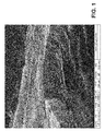
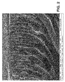
- the invention relates to a SPEEK diaphragm, and furthermore optionally relates to a component selected from the group consisting of ceramic particles, polyethersulfone and mixtures thereof for alkaline electrolysis having the following structure: a first microporous layer and a second layer having macroporous channels, where said macroporous channels start at the contact surface between the first and the second layer then extending and forming the outer surface of said second layer, where said macroporous channels increase in section and change direction as they approach said outer surface of said second layer, and where the wall of said macroporous channels has macropores.
- Said diaphragm hereinafter the diaphragm of the invention, can be produced in a simple manner and at a low cost by means of the chemically induced phase separation (CIPS) technique. Therefore in another aspect the invention relates to a production method for producing the diaphragm of the invention comprising the steps of:
- the diaphragm of the invention has a high mechanical stability, even, and a very reduced thicknesses, and thicknesses less than the thicknesses of the membranes conventionally used in alkaline electrolysis such as, for example, Zirfon® or polysulfone membranes.
- This fact is very advantageous inasmuch as it allows considerably reducing the amount of raw material necessary for manufacture, and therefore the manufacturing cost of the diaphragms since these raw materials are generally very expensive.
- the reduced thickness of the diaphragm of the invention is advantageous inasmuch as it allows that the energy necessary for carrying out the alkaline electrolysis is generally lower and therefore the alkaline electrolysis is more efficiently performed.
- the invention in another aspect relates to an alkaline electrolysis method comprising the use of at least one porous and semipermeable diaphragm of the invention.
- the invention relates to an electrolyzer comprising at least one diaphragm of the invention.
- the invention in a first aspect relates to a porous and semipermeable diaphragm comprising SPEEK, hereinafter the diaphragm of the invention.
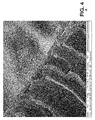
- the diaphragm of the invention has the following structure: a first microporous layer and a second layer having macroporous channels, where said macroporous channels start at the contact surface between the first and the second layer then extending and forming the outer surface of said second layer, where said macroporous channels increase in section and change direction as they approach said outer surface of said second layer, and where the wall of said macroporous channels has macropores.
- microporous layer has to be understood as a layer having micropores, i.e. pores with a mean size less than 2 nm, and “macroporous channels”, as channels with section greater than 50 nanometers, and “macropores”, as pores with a mean size greater than 50 nanometers.
- the equipment used for producing the SEM images is an InspectTM F high vacuum (10 -7 mbar) scanning electron microscope.
- the first layer can have a variable thickness, which depends on the temperature at which the polymer solution precipitation is carried out as described below.
- This Figure 4 further shows how the macroporous channels start at the contact surface with the first layer, and initially have an approximate section between 2 and 4 microns.
- the diaphragm of the invention has a mean porosity determined by means of the mercury porosimetry technique. Said porosity is generally comprised between 60% and 90%, and preferably between 75% and 85%.
- the equipment used these determinations is an Autopore IV porosimeter (Micromeritics), with four low pressure ports and two high pressure ports. The degasification conditions are 24 hours at 100°C.
- a diaphragm sample size usually of 50 mg is used, the specific surface of which is 16.2 m 2 /g.
- the total thickness of the diaphragm of the invention can vary within a wide range. In a particular embodiment the total thickness is comprised between 100 and 800 microns, and preferably between 100 and 200 microns.
- the first layer has a thickness, which as described below, depends on the conditions for producing the diaphragm and which can vary within a wide range. Generally said thickness is comprised between 450 and 950 nm. In a particular embodiment the thickness is comprised between 500 and 900 nm. In another particular embodiment it is comprised between 550 and 850 nm, and in another particular embodiment between 570 and 650 nm.
- the thicknesses are much less than the thicknesses of some conventional diaphragms, which entails a significant savings in the amount of raw materials needed for their production and further allows that the energy needed to carry out the alkaline electrolysis is generally less than those needed with conventional diaphragms and that the process is more efficient. Furthermore, despite its small thickness, the diaphragm has high mechanical strength.
- the diaphragm of the invention can comprise, in addition to SPEEK, an additional component selected from the group consisting of ceramic particles, polyethersulfone and mixtures thereof for alkaline electrolysis.
- the diaphragm of the invention comprises SPEEK and ceramic particles, which are homogeneously distributed in the polymer matrix.
- the ceramic particle content in principle, can vary within a wide range. Generally they are present in an amount comprised between 0.1% and 85% by weight, preferably between 0.5% and 40% by weight, more preferably between 1% and 20% by weight and even more preferably between 2% and 15% by weight with respect to the total weight of the diaphragm.
- the ceramic particles are selected from nanoparticles having a mean size equal to or less than 100 nm, and microparticles having a mean size comprised between 1 and 5 microns.
- the ceramic particles which can be used in the present invention can be, in principle, any ceramic particles.
- the particles can be embedded in the polymer matrix or can be bound by means of chemical bonds to SPEEK.
- the ceramic particles are first reacted with specific chemical compounds or functionalizing agents, for example mercaptosilanes, through which the functionalized ceramic particles subsequently bind to SPEEK.
- functionalizing agents favors the dispersion of the ceramic particles in the SPEEK polymer matrix and contributes to the better homogenization thereof.
- ceramic particles useful in the present invention are silica, zirconia, titania, clays, alumina, silicon carbide, titanates, zirconates, aluminosilicates, of any metal and mixtures thereof, among others.
- the ceramic particles are zirconia ceramic particles.
- the zirconia particles are derivatized with 3-mercaptopropyltrimethoxysilane (MPTMS) or any other similar chemical compound, which is bound to the surface of the ceramic particle through the silane leaving the mercapto functional group (-SH) free at the other end for its reaction with SPEEK
- MTMS 3-mercaptopropyltrimethoxysilane
- -SH mercapto functional group
- the diaphragm of the invention comprises, in addition to SPEEK, polyethersulfone, a polymer which is homogeneously distributed resulting in a composite and is present in an amount comprised between 0.5% and 40% by weight, preferably between 1% and 20% by weight, and more preferably between 5% and 13% by weight with respect to the total weight of the diaphragm.
- the diaphragm of the invention is semipermeable and has a controlled porosity in the sense that it allows the passage of hydroxyl groups through it but prevents, however, the passage of the H 2 and O 2 gases generated in the alkaline electrolysis in each cell.
- the diaphragm of the invention unlike the SPEEK diaphragms used in electrolysis by polymer electrolyte membrane (PEM), does not act as a proton carrier.
- the SPEEK sulfonic groups allow increasing the wetting of the diaphragm with respect to conventional PEEK and that the micropores are full of electrolyte blocking the passage of gas, unlike the SPEEK membranes used in PEM where the sulfonic groups are necessary for allowing proton migration therethrough.
- the present invention relates to a production method for producing the diaphragm of the invention as has been defined previously comprising the use of the chemically induced phase separation (CIPS) technique ( Hentze, H. P. and M. Antonietti (2002). "Porous polymers and resins for biotechnological and biomedical applications.” Reviews in Molecular Biotechnology 90(1): 27-53 ).
- CIPS chemically induced phase separation
- This method hereinafter the production method of the invention, comprises the following steps:
- PEEK polyether ether ketone
- PEEK polyether ether ketone
- It is a thermoplastic polymer which has glass transition temperatures about 143°C and 275°C and which melts at about 343°C. It shows great mechanical strength and chemical resistance. Since it has low ionic conductivity and low hydrophilicity it is subjected to sulfonation to yield SPEEK and to allow it to be conductive so that it can be applied in alkaline electrolysis.
- the PEEK serving as a starting material must have the lowest moisture content possible to prevent chemical property depletion which it undergoes if it retains water during sulfonation.
- the starting PEEK is generally used in pellet form and is subjected to dehydration. To that end it is typically kept in a stove at a temperature of 80-90°C for at least 10 hours. Then, if it is not immediately used, it is preferably isolated to prevent contact with the ambient moisture until the moment of use to produce SPEEK.
- Step (i) of the method comprises preparing a solution comprising SPEEK.
- Said preparation comprises PEEK sulfonation whereby an amount of PEEK is added to sulfuric acid.
- the amount of PEEK added can vary, in principle, within a wide range, but generally said amount is such that the PEEK concentration reached in sulfuric acid is comprised between 2 and 10% by weight, preferably between 4 and 6% by weight with respect to the total weight of the solution.
- the addition is performed under stirring so that the sulfonation is homogeneous, thus limiting polymer agglomeration.
- the sulfonation is left to occur for the time necessary until reaching a sulfonation degree comprised between 40% and 60%, suitable for the diaphragm manufacturing, SPEEK thus being produced.
- the sulfonation is carried out in an inert atmosphere. Variations in the temperature and the reaction time allow achieving the sulfonation degree desired in each case. In a particular embodiment the temperature is approximately 40°C and the reaction time is generally comprised between 6 and 24 hours, and is typically 8 hours.
- the solution is cast by spreading a determined amount of the solution on a support plane, which in a particular embodiment consists of a glass plate.
- the thickness of the solution layer which is deposited is preferably homogeneous and is controlled by means of a blade or spatula working by way of a scraper. In a particular case the commercial device Doctor Blade is used.
- the polymer precipitation is carried out by immersing the polymer solution into a non-solvent medium, preferably distilled water, but soluble for sulfuric acid, at a temperature, which can vary within a wide range. In a particular embodiment the temperature is comprised between 0°C and 80°C.
- a non-solvent medium preferably distilled water, but soluble for sulfuric acid
- the thickness of the first layer of the diaphragm of the invention varies depending on the temperature of the non-solvent medium in which the polymer solution is immersed, such that the thickness thereof is inversely proportional to the temperature of the medium. Therefore the temperature of the medium can be varied depending on the thickness to be produced for this first layer.
- the membrane After the membrane has precipitated it is washed with distilled water to remove the sulfuric acid residues retained therein until reaching a pH around 6 in the washing water. Typically the washing is carried out by immersing the precipitated membrane in distilled water for several hours with periodic water changes, until removing the acid residues and reaching said approximately a 6 pH value.
- the next step of the diaphragm preparation method is drying, in which the moisture retained in the previous washing step is reduced. Since it is removed from the last washing bath, the diaphragm is soaked in distilled water therefore a first drying step is performed generally on blotting paper. The drying is subsequently continued in a conventional manner until reducing the water content to a value of 5-10%.
- the drying can be performed in many ways, both at temperatures comprised between 60 and 80°C, in a stove, and naturally at room temperature, both methods being different in the time necessary to achieve complete drying.
- the diaphragm resulting from the previous step is cold rolled, the diaphragm of the invention being produced.
- the cold rolling is carried out to remove the possible membrane surface imperfections, such as high roughness, lumps, rippling, etc., and to prevent an operating performance drop in alkaline electrolysis due to the depositions of metal compound salt and of other substances which would reduce the active surface of the folded membrane formed on its surface.
- the cold rolling is carried out by means of the action of two rollers compressing the membrane and reducing and/or removing the presence of imperfections.
- the diaphragm comprises SPEEK and PES.
- the production method for producing it is the same as that previously described, except step (i) which comprises preparing a SPEEK and PES solution.
- This step comprises, as has been previously defined, PEEK sulfonation for which PEEK is added to sulfuric acid and a determined amount of PES amount is then poured in.
- the amount of PES added is variable, but it is such that the PES content in the diaphragm produced is generally comprised between 0.5% and 40% by weight, preferably between 1% and 20% by weight, and more preferably between 5% and 13% by weight with respect to the total weight of the diaphragm.
- the diaphragm comprises SPEEK and ceramic particles.
- the preparation method is also the same as that which has been previously described except step (i), which comprises preparing a SPEEK and ceramic particle solution.
- step (i) comprises preparing a SPEEK and ceramic particle solution.
- PEEK is added to sulfuric acid in the same amount previously described.
- the ceramic particles are added and it is stirred to reach a suitable particle dispersion in the resulting SPEEK solution.
- the ceramic particles which can be used are selected from nanoparticles having a mean size equal to or less than 100 nm, and microparticles having a mean size comprised between 1 and 5 microns.
- the type of ceramic particles has been previously described.
- the ceramic particles can be used after having been previously functionalized with different functionalizing agents generally through silanization reactions allowing the chemical reaction between the ceramic particles and SPEEK, which favors their dispersion in the SPEEK polymer matrix.
- the preparation of the SPEEK and functionalized ceramic particle solution comprises adding the ceramic particles to a suitable solvent under stirring to keep them in suspension, adding the functionalizing agent typically in excess for example in a 4:1 ratio (moles of functionalizing agent: moles of ceramic).
- the functionalization reaction can be carried out at different temperatures depending on various factors such as the type of ceramic and the agent selected in each case, and for a variable time, generally comprised between 6 and 24 hours.
- the resulting particles are filtered, washed with the same solvent used in the reaction to remove the excess of the functionalizing agent not bound to the ceramic particles, and the functionalized particles produced are dried, for example in a stove, typically at 80°C for 12 hours.
- the ceramic particles used are zirconia ceramic particles.
- the zirconia particles are previously functionalized with a functionalizing agent, for example with 3-mercaptopropyltrimethoxysilane (MPTMS), or any other similar functionalizing agent.
- MPTMS 3-mercaptopropyltrimethoxysilane
- the present invention relates to an alkaline electrolysis method comprising the use of at least one diaphragm of the invention previously defined.
- the method comprises the use of two or more diaphragms with sandwich-type structure.
- the use of the diaphragm of the invention in alkaline electrolysis allows obtaining low HTO values, i.e., achieves a very effective separation of H 2 and O 2 gases.
- comparative alkaline electrolysis assays have been carried out using the diaphragm of the invention and the commercial Zirfon® diaphragm; both the voltage and the separation selectivity (see Example 2) are clearly shown to be significantly improved, i.e., the energy needed for producing the same amount of H 2 is less and the H 2 stream produced with the diaphragm of the invention contains much less O 2 than the streams produced in electrolyzers using Zirfon® as a diaphragm.
- the diaphragm can be located in an alkaline electrolysis electrolyzer in any direction, i.e., with the first layer oriented towards the cathode or the anode. In a preferred embodiment the diaphragm is located with the first layer oriented towards the cathode.
- the diaphragm prevents the passage of the gases the first layer being microporous, the permeation-selective layer, whereas the macroporous channel layer support the diaphragm without increasing the electrical resistance of the assembly as a result of the high porosity due to its macroporous channels and its macroporous walls.
- the invention relates to an electrolyzer comprising at least one diaphragm according to the present invention.
- the electrolyzer further comprises a tank, a cathode, an anode and the two compartments separated by the diaphragm of the invention.
- the electrolyzer for alkaline electrolysis comprises two or more diaphragms with sandwich-type structure.
- the electrolytes for implementing the electrolysis method of the invention are conventional, typically NaOH or KOH in concentrations comprised between 20 and 40% by weight although higher and lower concentrations are also possible.
- the temperature at which the alkaline electrolysis method of the invention is carried out is generally comprised between 40 and 90°C although higher and lower temperatures are also possible.
- PEEK in pellet form LATI Ibérica®
- 96-98% sulfuric acid Sigma-Aldrich
- PES polyethersulfone
- nanozirconia with a mean particle size less than 100 nm Sigma Aldrich®
- the diaphragm thus produced has a thickness of 300 microns with a 42% sulfonation degree (measured by H-NMR technique).
- the variables shown for their comparison are the voltage needed to carry out the electrolysis, generated by a current source establishing the electric current for having the stipulated current density with a given voltage consumption; and the HTO, i.e., the hydrogen content present in the oxygen stream at the output of the gas separator which recirculates the electrolyte entrained by the gas stream.
- V Voltage
- the diaphragms of the invention are capable of operating with significantly lower voltage consumptions than the commercial material, especially with composite diaphragms (with PES) or with ceramic particles.
- An optimization is further achieved in the hydrogen-oxygen separation as the HTO value is reduced by more than 50% whereby streams that are purer than those produced using commercial Zirfon® membranes were produced.
- the use of the diaphragm of the invention involves optimizing raw material and resource use.
- SPEEK diaphragms have been prepared with thicknesses of only 100 microns with respect to the thickness of 400-500 microns [ International Journal of Hydrogen Energy Volume 36, Issue 13, July 2011, 7799-7806 ] measured for Zirfon®, which entails a production cost reduction, and furthermore, without causing problems in the mechanical strength of the diaphragm produced.
Landscapes
- Chemical & Material Sciences (AREA)
- Engineering & Computer Science (AREA)
- Chemical Kinetics & Catalysis (AREA)
- Electrochemistry (AREA)
- Organic Chemistry (AREA)
- Metallurgy (AREA)
- Materials Engineering (AREA)
- Life Sciences & Earth Sciences (AREA)
- Manufacturing & Machinery (AREA)
- Sustainable Development (AREA)
- Sustainable Energy (AREA)
- General Chemical & Material Sciences (AREA)
- Crystallography & Structural Chemistry (AREA)
- Inorganic Chemistry (AREA)
- Electrolytic Production Of Non-Metals, Compounds, Apparatuses Therefor (AREA)
Applications Claiming Priority (1)
| Application Number | Priority Date | Filing Date | Title |
|---|---|---|---|
| PCT/ES2011/070884 WO2013093126A1 (fr) | 2011-12-20 | 2011-12-20 | Membrane de speek destinée à l'électrolyse alcaline et utilisation correspondante |
Publications (2)
| Publication Number | Publication Date |
|---|---|
| EP2796592A1 true EP2796592A1 (fr) | 2014-10-29 |
| EP2796592B1 EP2796592B1 (fr) | 2016-09-14 |
Family
ID=45787226
Family Applications (1)
| Application Number | Title | Priority Date | Filing Date |
|---|---|---|---|
| EP11822822.0A Active EP2796592B1 (fr) | 2011-12-20 | 2011-12-20 | Membrane de speek destinée à l'électrolyse alcaline et utilisation correspondante |
Country Status (4)
| Country | Link |
|---|---|
| US (1) | US9376757B2 (fr) |
| EP (1) | EP2796592B1 (fr) |
| ES (1) | ES2606356T3 (fr) |
| WO (1) | WO2013093126A1 (fr) |
Cited By (2)
| Publication number | Priority date | Publication date | Assignee | Title |
|---|---|---|---|---|
| US11183700B2 (en) | 2019-09-16 | 2021-11-23 | Saudi Arabian Oil Company | Ion exchange membrane for a redox flow battery |
| JPWO2023048006A1 (fr) * | 2021-09-24 | 2023-03-30 |
Families Citing this family (7)
| Publication number | Priority date | Publication date | Assignee | Title |
|---|---|---|---|---|
| JP6905308B2 (ja) * | 2015-06-16 | 2021-07-21 | 川崎重工業株式会社 | アルカリ水電解用隔膜及びその製造方法 |
| JP7232110B2 (ja) * | 2019-04-01 | 2023-03-02 | 株式会社日本触媒 | アルカリ水電解用隔膜ならびに該隔膜の製造方法 |
| KR102328727B1 (ko) | 2020-01-21 | 2021-11-18 | 한국에너지기술연구원 | 가스 혼합을 억제하는 신규한 알칼리 수전해 격막 |
| EP3933069A1 (fr) * | 2020-07-03 | 2022-01-05 | Agfa-Gevaert Nv | Séparateur pour l'électrolyse de l'eau alcaline |
| CN115928145B (zh) * | 2022-12-28 | 2023-10-13 | 嘉庚创新实验室 | 一种碱性电解水制氢用有机-无机复合隔膜及其制备方法 |
| CN116024825A (zh) * | 2023-01-09 | 2023-04-28 | 北京碧水源膜科技有限公司 | 一种碱性电解水新型微孔隔膜的制备方法、所得产品及应用 |
| WO2025006862A1 (fr) * | 2023-06-30 | 2025-01-02 | W. L. Gore & Associates, Inc. | Diaphragme poreux d'électrolyseur, son procédé de production, électrolyseur comprenant le diaphragme poreux, et utilisation du diaphragme poreux dans l'électrolyse |
Family Cites Families (6)
| Publication number | Priority date | Publication date | Assignee | Title |
|---|---|---|---|---|
| GB8428525D0 (en) * | 1984-11-12 | 1984-12-19 | Ici Plc | Membranes |
| US4992485A (en) | 1988-10-11 | 1991-02-12 | The Dow Chemical Company | Microporous peek membranes and the preparation thereof |
| GB8901672D0 (en) | 1989-01-26 | 1989-03-15 | Ici Plc | Membranes |
| BE1006659A3 (nl) * | 1992-01-29 | 1994-11-08 | Vito | Werkwijze ter vervaardiging van een membraan, aldus vervaardigd membraan en elektrochemische cel met zulk membraan. |
| US20080004443A1 (en) * | 2006-07-03 | 2008-01-03 | General Electric Company | Sulfonated polyaryletherketone-block-polyethersulfone copolymers |
| KR100928718B1 (ko) * | 2007-10-09 | 2009-11-27 | 성균관대학교산학협력단 | 유기 용매 건조법에 의한 균일하게 황산기가 부착된peek 전해질 막의 제조 방법 |
-
2011
- 2011-12-20 ES ES11822822.0T patent/ES2606356T3/es active Active
- 2011-12-20 EP EP11822822.0A patent/EP2796592B1/fr active Active
- 2011-12-20 WO PCT/ES2011/070884 patent/WO2013093126A1/fr not_active Ceased
- 2011-12-20 US US14/367,432 patent/US9376757B2/en active Active
Cited By (3)
| Publication number | Priority date | Publication date | Assignee | Title |
|---|---|---|---|---|
| US11183700B2 (en) | 2019-09-16 | 2021-11-23 | Saudi Arabian Oil Company | Ion exchange membrane for a redox flow battery |
| JPWO2023048006A1 (fr) * | 2021-09-24 | 2023-03-30 | ||
| EP4407072A4 (fr) * | 2021-09-24 | 2025-08-27 | Nippon Catalytic Chem Ind | Procédé de production d'un diaphragme d'utilisation d'électrolyse d'eau alcaline, et diaphragme d'utilisation d'électrolyse d'eau alcaline |
Also Published As
| Publication number | Publication date |
|---|---|
| ES2606356T3 (es) | 2017-03-23 |
| WO2013093126A1 (fr) | 2013-06-27 |
| EP2796592B1 (fr) | 2016-09-14 |
| US9376757B2 (en) | 2016-06-28 |
| US20140332403A1 (en) | 2014-11-13 |
Similar Documents
| Publication | Publication Date | Title |
|---|---|---|
| EP2796592B1 (fr) | Membrane de speek destinée à l'électrolyse alcaline et utilisation correspondante | |
| CN107408743B (zh) | 空气极、水电解阳极、金属空气电池及水电解装置 | |
| KR102436919B1 (ko) | Koh 전해액 환경에서 이온 전도도가 향상된 알칼라인 수전해 셀룰로오스 격막 | |
| KR102328727B1 (ko) | 가스 혼합을 억제하는 신규한 알칼리 수전해 격막 | |
| KR102762559B1 (ko) | 수소 투과도 감소 표면층을 가지는 다공성 분리막 및 이의 제조방법 | |
| EA027322B1 (ru) | Газодиффузионный электрод | |
| KR20220081811A (ko) | 술폰화된 폴리프로필렌 메쉬 지지체를 이용한 수전해 다공성 격막 및 이의 제조방법 | |
| KR20080109926A (ko) | 전해질-침투 전지용 가스-확산 전극 | |
| JP7839808B2 (ja) | イオン伝導膜、その製造方法、その膜を含むセル、及びそのセルを含むプラント | |
| Du et al. | Tailoring microstructure of polysulfone composite membranes for alkaline water electrolysis | |
| KR101580094B1 (ko) | 해조류를 이용한 이종 원소 함유 다공성 탄소체 및 이의 제조방법 | |
| JP7605744B2 (ja) | 複合フィルムならびにその製造および使用の方法 | |
| Khan et al. | Fuel electrode materials for solid oxide electrolysis cells (SOECs) | |
| KR20260025385A (ko) | 이온-전도성 멤브레인, 그와 같은 멤브레인의 제조 방법, 그와 같은 멤브레인을 포함하는 전기화학 전지 및 그와 같은 전지를 포함하는 플랜트 | |
| JP4998713B2 (ja) | イオン透過性隔膜 | |
| EP4547742B1 (fr) | Procédés de production de membranes échangeuses d'ions composites non poreuses pour l'électrolyse de l'eau et dispositifs obtenus à partir de ces membranes | |
| CN120888978B (zh) | 一种基于羟基氧化镍的碱性电解水隔膜及其制备方法与应用 | |
| JP2011060500A (ja) | プロトン伝導性複合電解質膜、それを用いた膜電極接合体及び燃料電池、並びにそのプロトン伝導性複合電解質膜の製造方法 | |
| JP2010229431A (ja) | イオン透過性隔膜及びその製造方法 | |
| JP2010244932A (ja) | プロトン伝導性複合電解質膜、それを用いた膜電極接合体及び燃料電池、並びにそのプロトン伝導性複合電解質膜の製造方法 | |
| CN118563362B (zh) | 一种制备碱性电解槽隔膜的方法 | |
| Khan et al. | Electrolysis Cells (SOECs) | |
| CN120330798A (zh) | 一种基于超亲水静电自组装材料的复合隔膜及其制备方法 | |
| CN121853045A (zh) | 一种多阻气层的高效电解水制氢复合隔膜 | |
| JP2026014024A (ja) | 重水分離用触媒およびその製造方法、重水分離セル、並びに重水分離装置 |
Legal Events
| Date | Code | Title | Description |
|---|---|---|---|
| PUAI | Public reference made under article 153(3) epc to a published international application that has entered the european phase |
Free format text: ORIGINAL CODE: 0009012 |
|
| 17P | Request for examination filed |
Effective date: 20140718 |
|
| AK | Designated contracting states |
Kind code of ref document: A1 Designated state(s): AL AT BE BG CH CY CZ DE DK EE ES FI FR GB GR HR HU IE IS IT LI LT LU LV MC MK MT NL NO PL PT RO RS SE SI SK SM TR |
|
| DAX | Request for extension of the european patent (deleted) | ||
| 17Q | First examination report despatched |
Effective date: 20150717 |
|
| GRAP | Despatch of communication of intention to grant a patent |
Free format text: ORIGINAL CODE: EPIDOSNIGR1 |
|
| INTG | Intention to grant announced |
Effective date: 20160506 |
|
| GRAS | Grant fee paid |
Free format text: ORIGINAL CODE: EPIDOSNIGR3 |
|
| GRAA | (expected) grant |
Free format text: ORIGINAL CODE: 0009210 |
|
| AK | Designated contracting states |
Kind code of ref document: B1 Designated state(s): AL AT BE BG CH CY CZ DE DK EE ES FI FR GB GR HR HU IE IS IT LI LT LU LV MC MK MT NL NO PL PT RO RS SE SI SK SM TR |
|
| REG | Reference to a national code |
Ref country code: GB Ref legal event code: FG4D |
|
| REG | Reference to a national code |
Ref country code: CH Ref legal event code: EP |
|
| REG | Reference to a national code |
Ref country code: IE Ref legal event code: FG4D |
|
| REG | Reference to a national code |
Ref country code: AT Ref legal event code: REF Ref document number: 829089 Country of ref document: AT Kind code of ref document: T Effective date: 20161015 |
|
| REG | Reference to a national code |
Ref country code: DE Ref legal event code: R096 Ref document number: 602011030432 Country of ref document: DE |
|
| REG | Reference to a national code |
Ref country code: FR Ref legal event code: PLFP Year of fee payment: 6 |
|
| REG | Reference to a national code |
Ref country code: LT Ref legal event code: MG4D |
|
| REG | Reference to a national code |
Ref country code: NL Ref legal event code: MP Effective date: 20160914 |
|
| PG25 | Lapsed in a contracting state [announced via postgrant information from national office to epo] |
Ref country code: FI Free format text: LAPSE BECAUSE OF FAILURE TO SUBMIT A TRANSLATION OF THE DESCRIPTION OR TO PAY THE FEE WITHIN THE PRESCRIBED TIME-LIMIT Effective date: 20160914 Ref country code: LT Free format text: LAPSE BECAUSE OF FAILURE TO SUBMIT A TRANSLATION OF THE DESCRIPTION OR TO PAY THE FEE WITHIN THE PRESCRIBED TIME-LIMIT Effective date: 20160914 Ref country code: RS Free format text: LAPSE BECAUSE OF FAILURE TO SUBMIT A TRANSLATION OF THE DESCRIPTION OR TO PAY THE FEE WITHIN THE PRESCRIBED TIME-LIMIT Effective date: 20160914 Ref country code: HR Free format text: LAPSE BECAUSE OF FAILURE TO SUBMIT A TRANSLATION OF THE DESCRIPTION OR TO PAY THE FEE WITHIN THE PRESCRIBED TIME-LIMIT Effective date: 20160914 Ref country code: NO Free format text: LAPSE BECAUSE OF FAILURE TO SUBMIT A TRANSLATION OF THE DESCRIPTION OR TO PAY THE FEE WITHIN THE PRESCRIBED TIME-LIMIT Effective date: 20161214 |
|
| REG | Reference to a national code |
Ref country code: AT Ref legal event code: MK05 Ref document number: 829089 Country of ref document: AT Kind code of ref document: T Effective date: 20160914 |
|
| PG25 | Lapsed in a contracting state [announced via postgrant information from national office to epo] |
Ref country code: GR Free format text: LAPSE BECAUSE OF FAILURE TO SUBMIT A TRANSLATION OF THE DESCRIPTION OR TO PAY THE FEE WITHIN THE PRESCRIBED TIME-LIMIT Effective date: 20161215 Ref country code: SE Free format text: LAPSE BECAUSE OF FAILURE TO SUBMIT A TRANSLATION OF THE DESCRIPTION OR TO PAY THE FEE WITHIN THE PRESCRIBED TIME-LIMIT Effective date: 20160914 Ref country code: NL Free format text: LAPSE BECAUSE OF FAILURE TO SUBMIT A TRANSLATION OF THE DESCRIPTION OR TO PAY THE FEE WITHIN THE PRESCRIBED TIME-LIMIT Effective date: 20160914 Ref country code: LV Free format text: LAPSE BECAUSE OF FAILURE TO SUBMIT A TRANSLATION OF THE DESCRIPTION OR TO PAY THE FEE WITHIN THE PRESCRIBED TIME-LIMIT Effective date: 20160914 |
|
| PG25 | Lapsed in a contracting state [announced via postgrant information from national office to epo] |
Ref country code: RO Free format text: LAPSE BECAUSE OF FAILURE TO SUBMIT A TRANSLATION OF THE DESCRIPTION OR TO PAY THE FEE WITHIN THE PRESCRIBED TIME-LIMIT Effective date: 20160914 Ref country code: EE Free format text: LAPSE BECAUSE OF FAILURE TO SUBMIT A TRANSLATION OF THE DESCRIPTION OR TO PAY THE FEE WITHIN THE PRESCRIBED TIME-LIMIT Effective date: 20160914 |
|
| PG25 | Lapsed in a contracting state [announced via postgrant information from national office to epo] |
Ref country code: AT Free format text: LAPSE BECAUSE OF FAILURE TO SUBMIT A TRANSLATION OF THE DESCRIPTION OR TO PAY THE FEE WITHIN THE PRESCRIBED TIME-LIMIT Effective date: 20160914 Ref country code: SK Free format text: LAPSE BECAUSE OF FAILURE TO SUBMIT A TRANSLATION OF THE DESCRIPTION OR TO PAY THE FEE WITHIN THE PRESCRIBED TIME-LIMIT Effective date: 20160914 Ref country code: PL Free format text: LAPSE BECAUSE OF FAILURE TO SUBMIT A TRANSLATION OF THE DESCRIPTION OR TO PAY THE FEE WITHIN THE PRESCRIBED TIME-LIMIT Effective date: 20160914 Ref country code: PT Free format text: LAPSE BECAUSE OF FAILURE TO SUBMIT A TRANSLATION OF THE DESCRIPTION OR TO PAY THE FEE WITHIN THE PRESCRIBED TIME-LIMIT Effective date: 20170116 Ref country code: IS Free format text: LAPSE BECAUSE OF FAILURE TO SUBMIT A TRANSLATION OF THE DESCRIPTION OR TO PAY THE FEE WITHIN THE PRESCRIBED TIME-LIMIT Effective date: 20170114 Ref country code: BE Free format text: LAPSE BECAUSE OF FAILURE TO SUBMIT A TRANSLATION OF THE DESCRIPTION OR TO PAY THE FEE WITHIN THE PRESCRIBED TIME-LIMIT Effective date: 20160914 Ref country code: CZ Free format text: LAPSE BECAUSE OF FAILURE TO SUBMIT A TRANSLATION OF THE DESCRIPTION OR TO PAY THE FEE WITHIN THE PRESCRIBED TIME-LIMIT Effective date: 20160914 Ref country code: SM Free format text: LAPSE BECAUSE OF FAILURE TO SUBMIT A TRANSLATION OF THE DESCRIPTION OR TO PAY THE FEE WITHIN THE PRESCRIBED TIME-LIMIT Effective date: 20160914 Ref country code: BG Free format text: LAPSE BECAUSE OF FAILURE TO SUBMIT A TRANSLATION OF THE DESCRIPTION OR TO PAY THE FEE WITHIN THE PRESCRIBED TIME-LIMIT Effective date: 20161214 |
|
| REG | Reference to a national code |
Ref country code: DE Ref legal event code: R097 Ref document number: 602011030432 Country of ref document: DE |
|
| PLBE | No opposition filed within time limit |
Free format text: ORIGINAL CODE: 0009261 |
|
| STAA | Information on the status of an ep patent application or granted ep patent |
Free format text: STATUS: NO OPPOSITION FILED WITHIN TIME LIMIT |
|
| PG25 | Lapsed in a contracting state [announced via postgrant information from national office to epo] |
Ref country code: DK Free format text: LAPSE BECAUSE OF FAILURE TO SUBMIT A TRANSLATION OF THE DESCRIPTION OR TO PAY THE FEE WITHIN THE PRESCRIBED TIME-LIMIT Effective date: 20160914 |
|
| REG | Reference to a national code |
Ref country code: CH Ref legal event code: PL |
|
| 26N | No opposition filed |
Effective date: 20170615 |
|
| PG25 | Lapsed in a contracting state [announced via postgrant information from national office to epo] |
Ref country code: MC Free format text: LAPSE BECAUSE OF FAILURE TO SUBMIT A TRANSLATION OF THE DESCRIPTION OR TO PAY THE FEE WITHIN THE PRESCRIBED TIME-LIMIT Effective date: 20160914 |
|
| REG | Reference to a national code |
Ref country code: IE Ref legal event code: MM4A |
|
| PG25 | Lapsed in a contracting state [announced via postgrant information from national office to epo] |
Ref country code: CH Free format text: LAPSE BECAUSE OF NON-PAYMENT OF DUE FEES Effective date: 20161231 Ref country code: LU Free format text: LAPSE BECAUSE OF NON-PAYMENT OF DUE FEES Effective date: 20161220 Ref country code: LI Free format text: LAPSE BECAUSE OF NON-PAYMENT OF DUE FEES Effective date: 20161231 |
|
| PG25 | Lapsed in a contracting state [announced via postgrant information from national office to epo] |
Ref country code: SI Free format text: LAPSE BECAUSE OF FAILURE TO SUBMIT A TRANSLATION OF THE DESCRIPTION OR TO PAY THE FEE WITHIN THE PRESCRIBED TIME-LIMIT Effective date: 20160914 Ref country code: IE Free format text: LAPSE BECAUSE OF NON-PAYMENT OF DUE FEES Effective date: 20161220 |
|
| REG | Reference to a national code |
Ref country code: FR Ref legal event code: PLFP Year of fee payment: 7 |
|
| PG25 | Lapsed in a contracting state [announced via postgrant information from national office to epo] |
Ref country code: HU Free format text: LAPSE BECAUSE OF FAILURE TO SUBMIT A TRANSLATION OF THE DESCRIPTION OR TO PAY THE FEE WITHIN THE PRESCRIBED TIME-LIMIT; INVALID AB INITIO Effective date: 20111220 |
|
| PG25 | Lapsed in a contracting state [announced via postgrant information from national office to epo] |
Ref country code: MK Free format text: LAPSE BECAUSE OF FAILURE TO SUBMIT A TRANSLATION OF THE DESCRIPTION OR TO PAY THE FEE WITHIN THE PRESCRIBED TIME-LIMIT Effective date: 20160914 Ref country code: CY Free format text: LAPSE BECAUSE OF FAILURE TO SUBMIT A TRANSLATION OF THE DESCRIPTION OR TO PAY THE FEE WITHIN THE PRESCRIBED TIME-LIMIT Effective date: 20160914 |
|
| PG25 | Lapsed in a contracting state [announced via postgrant information from national office to epo] |
Ref country code: MT Free format text: LAPSE BECAUSE OF NON-PAYMENT OF DUE FEES Effective date: 20161220 |
|
| PG25 | Lapsed in a contracting state [announced via postgrant information from national office to epo] |
Ref country code: TR Free format text: LAPSE BECAUSE OF FAILURE TO SUBMIT A TRANSLATION OF THE DESCRIPTION OR TO PAY THE FEE WITHIN THE PRESCRIBED TIME-LIMIT Effective date: 20160914 Ref country code: AL Free format text: LAPSE BECAUSE OF FAILURE TO SUBMIT A TRANSLATION OF THE DESCRIPTION OR TO PAY THE FEE WITHIN THE PRESCRIBED TIME-LIMIT Effective date: 20160914 |
|
| REG | Reference to a national code |
Ref country code: DE Ref legal event code: R081 Ref document number: 602011030432 Country of ref document: DE Owner name: INGETEAM POWER TECHNOLOGY, S.A., ZAMUDIO, ES Free format text: FORMER OWNERS: ACCIONA ENERGIA, S.A., SARRIGUREN, NAVARRA, ES; INGETEAM POWER TECHNOLOGY, S.A., ZAMUDIO, BIZKAIA, ES Ref country code: DE Ref legal event code: R081 Ref document number: 602011030432 Country of ref document: DE Owner name: ACCIONA GENERACION RENOVABLE, S.A., EGUES, ES Free format text: FORMER OWNERS: ACCIONA ENERGIA, S.A., SARRIGUREN, NAVARRA, ES; INGETEAM POWER TECHNOLOGY, S.A., ZAMUDIO, BIZKAIA, ES |
|
| P01 | Opt-out of the competence of the unified patent court (upc) registered |
Effective date: 20230602 |
|
| REG | Reference to a national code |
Ref country code: DE Ref legal event code: R082 Ref document number: 602011030432 Country of ref document: DE Representative=s name: KRAUS & LEDERER PARTGMBB, DE |
|
| PGFP | Annual fee paid to national office [announced via postgrant information from national office to epo] |
Ref country code: DE Payment date: 20241210 Year of fee payment: 14 |
|
| PGFP | Annual fee paid to national office [announced via postgrant information from national office to epo] |
Ref country code: GB Payment date: 20241114 Year of fee payment: 14 |
|
| PGFP | Annual fee paid to national office [announced via postgrant information from national office to epo] |
Ref country code: FR Payment date: 20241127 Year of fee payment: 14 |
|
| PGFP | Annual fee paid to national office [announced via postgrant information from national office to epo] |
Ref country code: IT Payment date: 20241202 Year of fee payment: 14 |
|
| PGFP | Annual fee paid to national office [announced via postgrant information from national office to epo] |
Ref country code: ES Payment date: 20250102 Year of fee payment: 14 |