EP2796659A2 - Système rotatif orientable pour forage vertical - Google Patents
Système rotatif orientable pour forage vertical Download PDFInfo
- Publication number
- EP2796659A2 EP2796659A2 EP14157833.6A EP14157833A EP2796659A2 EP 2796659 A2 EP2796659 A2 EP 2796659A2 EP 14157833 A EP14157833 A EP 14157833A EP 2796659 A2 EP2796659 A2 EP 2796659A2
- Authority
- EP
- European Patent Office
- Prior art keywords
- wellbore
- drilling
- bias
- control module
- assembly
- Prior art date
- Legal status (The legal status is an assumption and is not a legal conclusion. Google has not performed a legal analysis and makes no representation as to the accuracy of the status listed.)
- Withdrawn
Links
- 238000005553 drilling Methods 0.000 title claims abstract description 51
- 239000012530 fluid Substances 0.000 claims abstract description 33
- 238000012544 monitoring process Methods 0.000 claims description 3
- 238000000034 method Methods 0.000 claims 1
- 230000000712 assembly Effects 0.000 description 5
- 238000000429 assembly Methods 0.000 description 5
- 230000015572 biosynthetic process Effects 0.000 description 5
- 239000003550 marker Substances 0.000 description 4
- 230000005355 Hall effect Effects 0.000 description 2
- RYGMFSIKBFXOCR-UHFFFAOYSA-N Copper Chemical group [Cu] RYGMFSIKBFXOCR-UHFFFAOYSA-N 0.000 description 1
- XQCFHQBGMWUEMY-ZPUQHVIOSA-N Nitrovin Chemical compound C=1C=C([N+]([O-])=O)OC=1\C=C\C(=NNC(=N)N)\C=C\C1=CC=C([N+]([O-])=O)O1 XQCFHQBGMWUEMY-ZPUQHVIOSA-N 0.000 description 1
- 229910052802 copper Inorganic materials 0.000 description 1
- 239000010949 copper Substances 0.000 description 1
- 230000008878 coupling Effects 0.000 description 1
- 238000010168 coupling process Methods 0.000 description 1
- 238000005859 coupling reaction Methods 0.000 description 1
- 230000005484 gravity Effects 0.000 description 1
- 230000002401 inhibitory effect Effects 0.000 description 1
- 238000005259 measurement Methods 0.000 description 1
- 230000007246 mechanism Effects 0.000 description 1
- 230000015654 memory Effects 0.000 description 1
- 239000003381 stabilizer Substances 0.000 description 1
Images





Classifications
-
- G—PHYSICS
- G01—MEASURING; TESTING
- G01D—MEASURING NOT SPECIALLY ADAPTED FOR A SPECIFIC VARIABLE; ARRANGEMENTS FOR MEASURING TWO OR MORE VARIABLES NOT COVERED IN A SINGLE OTHER SUBCLASS; TARIFF METERING APPARATUS; MEASURING OR TESTING NOT OTHERWISE PROVIDED FOR
- G01D5/00—Mechanical means for transferring the output of a sensing member; Means for converting the output of a sensing member to another variable where the form or nature of the sensing member does not constrain the means for converting; Transducers not specially adapted for a specific variable
- G01D5/12—Mechanical means for transferring the output of a sensing member; Means for converting the output of a sensing member to another variable where the form or nature of the sensing member does not constrain the means for converting; Transducers not specially adapted for a specific variable using electric or magnetic means
- G01D5/14—Mechanical means for transferring the output of a sensing member; Means for converting the output of a sensing member to another variable where the form or nature of the sensing member does not constrain the means for converting; Transducers not specially adapted for a specific variable using electric or magnetic means influencing the magnitude of a current or voltage
- G01D5/142—Mechanical means for transferring the output of a sensing member; Means for converting the output of a sensing member to another variable where the form or nature of the sensing member does not constrain the means for converting; Transducers not specially adapted for a specific variable using electric or magnetic means influencing the magnitude of a current or voltage using Hall-effect devices
- G01D5/145—Mechanical means for transferring the output of a sensing member; Means for converting the output of a sensing member to another variable where the form or nature of the sensing member does not constrain the means for converting; Transducers not specially adapted for a specific variable using electric or magnetic means influencing the magnitude of a current or voltage using Hall-effect devices influenced by the relative movement between the Hall device and magnetic fields
-
- E—FIXED CONSTRUCTIONS
- E21—EARTH OR ROCK DRILLING; MINING
- E21B—EARTH OR ROCK DRILLING; OBTAINING OIL, GAS, WATER, SOLUBLE OR MELTABLE MATERIALS OR A SLURRY OF MINERALS FROM WELLS
- E21B7/00—Special methods or apparatus for drilling
- E21B7/04—Directional drilling
- E21B7/10—Correction of deflected boreholes
-
- E—FIXED CONSTRUCTIONS
- E21—EARTH OR ROCK DRILLING; MINING
- E21B—EARTH OR ROCK DRILLING; OBTAINING OIL, GAS, WATER, SOLUBLE OR MELTABLE MATERIALS OR A SLURRY OF MINERALS FROM WELLS
- E21B17/00—Drilling rods or pipes; Flexible drill strings; Kellies; Drill collars; Sucker rods; Cables; Casings; Tubings
- E21B17/10—Wear protectors; Centralising devices, e.g. stabilisers
- E21B17/1014—Flexible or expansible centering means, e.g. with pistons pressing against the wall of the well
-
- E—FIXED CONSTRUCTIONS
- E21—EARTH OR ROCK DRILLING; MINING
- E21B—EARTH OR ROCK DRILLING; OBTAINING OIL, GAS, WATER, SOLUBLE OR MELTABLE MATERIALS OR A SLURRY OF MINERALS FROM WELLS
- E21B44/00—Automatic control systems specially adapted for drilling operations, i.e. self-operating systems which function to carry out or modify a drilling operation without intervention of a human operator, e.g. computer-controlled drilling systems; Systems specially adapted for monitoring a plurality of drilling variables or conditions
-
- E—FIXED CONSTRUCTIONS
- E21—EARTH OR ROCK DRILLING; MINING
- E21B—EARTH OR ROCK DRILLING; OBTAINING OIL, GAS, WATER, SOLUBLE OR MELTABLE MATERIALS OR A SLURRY OF MINERALS FROM WELLS
- E21B47/00—Survey of boreholes or wells
- E21B47/12—Means for transmitting measuring-signals or control signals from the well to the surface, or from the surface to the well, e.g. for logging while drilling
-
- E—FIXED CONSTRUCTIONS
- E21—EARTH OR ROCK DRILLING; MINING
- E21B—EARTH OR ROCK DRILLING; OBTAINING OIL, GAS, WATER, SOLUBLE OR MELTABLE MATERIALS OR A SLURRY OF MINERALS FROM WELLS
- E21B7/00—Special methods or apparatus for drilling
- E21B7/04—Directional drilling
- E21B7/06—Deflecting the direction of boreholes
- E21B7/062—Deflecting the direction of boreholes the tool shaft rotating inside a non-rotating guide travelling with the shaft
-
- E—FIXED CONSTRUCTIONS
- E21—EARTH OR ROCK DRILLING; MINING
- E21B—EARTH OR ROCK DRILLING; OBTAINING OIL, GAS, WATER, SOLUBLE OR MELTABLE MATERIALS OR A SLURRY OF MINERALS FROM WELLS
- E21B45/00—Measuring the drilling time or rate of penetration
-
- E—FIXED CONSTRUCTIONS
- E21—EARTH OR ROCK DRILLING; MINING
- E21B—EARTH OR ROCK DRILLING; OBTAINING OIL, GAS, WATER, SOLUBLE OR MELTABLE MATERIALS OR A SLURRY OF MINERALS FROM WELLS
- E21B47/00—Survey of boreholes or wells
- E21B47/02—Determining slope or direction
- E21B47/024—Determining slope or direction of devices in the borehole
-
- E—FIXED CONSTRUCTIONS
- E21—EARTH OR ROCK DRILLING; MINING
- E21B—EARTH OR ROCK DRILLING; OBTAINING OIL, GAS, WATER, SOLUBLE OR MELTABLE MATERIALS OR A SLURRY OF MINERALS FROM WELLS
- E21B47/00—Survey of boreholes or wells
- E21B47/12—Means for transmitting measuring-signals or control signals from the well to the surface, or from the surface to the well, e.g. for logging while drilling
- E21B47/14—Means for transmitting measuring-signals or control signals from the well to the surface, or from the surface to the well, e.g. for logging while drilling using acoustic waves
- E21B47/18—Means for transmitting measuring-signals or control signals from the well to the surface, or from the surface to the well, e.g. for logging while drilling using acoustic waves through the well fluid, e.g. mud pressure pulse telemetry
Definitions
- Embodiments of the invention generally relate to steerable drilling systems for drilling vertical wellbores.
- Directional drilling involves varying or controlling the direction of a wellbore as it is being drilled.
- the goal of directional drilling is to reach or maintain a position within a target subterranean destination or formation with the drilling string.
- the drilling direction may be controlled to direct the wellbore towards a desired target destination, to control the wellbore horizontally to maintain it within a desired payzone, or to correct for unwanted or undesired deviations from a desired or predetermined path.
- directional drilling may include deflection or deviation of a wellbore along a predetermined or desired path in order to reach or intersect with, or to maintain a position within, a specific subterranean formation or target.
- the predetermined path typically includes a depth where initial deflection or deviation occurs and a schedule of desired deviation angles and directions over the remainder of the wellbore.
- deflection or deviation is a change in the direction of the wellbore from the current wellbore path.
- a rotary steerable drilling system for drilling vertical wellbores A rotary steerable drilling system for drilling vertical wellbores.
- Embodiments of the invention relate to a rotary steerable drilling system for drilling wellbores.
- the system is operable to maintain a substantially vertical wellbore drilling path. If the system begins to deviate from the vertical drilling path (due to the wellbore formation characteristics for example), then the system is operable to automatically self correct and force the system back toward the vertical drilling path trajectory.
- the system may be a self contained, electronically controlled, push bit system.
- the system may be rotated from the surface and/or may include conventional mud motors for providing additional rotational drill bit speed.
- the system may include one or more individually controllable and replaceable bias pads operable to force or push the drill bit in a desired direction.
- the bias pads may allow direction control of up to 5 percent over-gauge of the wellbore diameter. In the event of a failure, the system is designed to have a natural drop tendency to drill vertically.
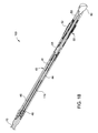
- FIGS 1A and 1B illustrate a rotary steerable drilling system 100 according to one embodiment.
- the system 100 includes a drill string 10 for rotating a drill bit 60 from the surface, an optional hydraulically actuated, straight housing motor 20 for providing additional rotational speed, and a stabilizer 30 for maintaining the system 100 within the center of a wellbore while drilling.
- the drill string 10 may be coupled to a conventional mud motor, which is coupled to a barrel collar, or if no motor is used, the drill string 10 may be coupled to the barrel collar via a drill collar as known in the art.
- the system 100 further includes a barrel collar, referred to herein as a control collar 40, for supporting control modules, power supplies, mud pulsers, valves, measurement/logging while drilling components, and/or various other components and electronic packages known in the art.
- the control collar 40 may include one or more micro-processors, memories, mass storage devices, and well known support circuits such as power supplies, clocks, cache, input/output circuits, and the like.
- the control collar 40 may include a control module 41, a power supply 44 (such as a battery), a pulser driver 45, and a pulser 46.
- the control collar 40 may be operable to communicate information to the surface and to one or more components of the system 100 as further described herein.
- the control collar 40 is operable to transmit data to the surface via mud pulse telemetry.
- the data may include the inclination and/or the rotational speed of the system 100.
- the system 100 further includes a self-contained, steerable assembly 50 having rotating sections 51, 53 and a non-rotating section 52 disposed between the rotating sections 51, 53.
- the rotating section 53 may include a tubular member coupled to the drill bit 60.
- the rotating section 51 may include a tubular member forming a drive shaft 55 that is disposed through the non-rotating section 52 and that is coupled to the tubular member of the rotating section 53 for transmitting rotation to the drill bit 60.
- An internal bore 110 may be disposed through the system 100 from the drill string 10 to the drill bit 60.
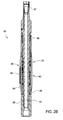
- FIGS 2A and 2B illustrate the steerable assembly 50 according to one embodiment.
- the rotating section 51 may include a tubular member for coupling the assembly 50 to the control collar 40 via one or more tubular threaded connections.
- An electrical connector 57 may be used to electrically connect the control collar 40 to the steerable assembly 50.
- the drive shaft 55 of the rotating section 51 may extend through the non-rotating section 52 and may be threadedly coupled to the tubular member of the rotating section 53.
- the non-rotating section 52 may include one or more replaceable bias pads 54 that are supported by an outer housing 58.
- the outer housing 58 may be coupled to balance pistons 56 (comprising pistons/biasing members) disposed at opposite ends, which are supported by the tubular member of the rotating section 51.
- the balance pistons 56 create a sealed chamber and balance the pressure between the internal components of the steerable assembly 50 with respect to the surrounding wellbore pressure as known in the art.
- the steerable assembly 50 may further include a slip ring assembly 70, a control valve assembly 80, and a pump assembly 90.
- the slip ring assembly 70 is operable to communicate between the control module 41 (illustrated in Figure 6 ) in the control collar 40 and the non-rotating control valve assembly 80.
- the control valve assembly 80 controls the amount of fluid pressure and thus force that is applied to each bias pad 54.
- the pump assembly 90 continuously pumps fluid through the self contained steerable assembly 50 between a fluid reservoir, the control valve assembly 80, and at least one piston 59 for biasing each bias pad 54 as further described below.
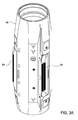
- FIGS 3A-3C illustrate the outer housing 58 for supporting the bias pads 54 and pistons 59 operable to bias the pads 54 radially outward.
- Three bias pads 54 are symmetrically and pivotably coupled to the outer housing 58 at a first end 61.
- the opposite end of each bias pad 54 may be forced radially outward into engagement with the surrounding wellbore by the pistons 59.
- the bias pads 54 may be forced directly radially outward into engagement with the surrounding wellbore as opposed to be pivoted or rotated radially outward.
- Each bias pad 54 may be engaged by one, two, or more pistons 59.
- the pistons 59 are forced into engagement with the bias pad 54 using pressurized fluid that is driven by the pump assembly 90.
- the amount of fluid pressure applied to each piston 59 is controlled by the control valve assembly 80.
- FIGS 4A and 4B illustrate the control valve assembly 80 and the pump assembly 90 (with the outer housing 58 removed for clarity).
- Each bias pad 54 may be controlled individually by one or more control valve assemblies 80 and pump assemblies 90.
- the control valve assembly 80 may include a support housing 85 for supporting one or more solenoid valves having a coil 81 and a plunger 82.
- the solenoid valves are hydraulically connected to the pistons 59 of each bias pad 54, and are electrically connected to the control module 41 of the control collar 40 via the slip ring assembly 70.
- the amount of current flowing through the coil 81 determines the position of the plunger 82 for (at least partially) opening and closing fluid flow into an inlet flow passage 83 and out of an outlet flow passage 84 formed in the support housing 85.
- the inlet flow passage 83 is in fluid communication with the high pressure side of the pistons 59 acting on the bias pads 54.
- the outlet flow passage 84 is in fluid communication with the lower pressure return side of the fluid reservoir.
- the plunger 82 may be moved to a position that permits uninhibited fluid flow from the inlet flow passage 83 to the outlet flow passage 84, thereby minimizing the amount of pressure applied to the pistons 59 and thus applying a minimal, if any, amount of force to the bias pads 54. If a maximum amount of current is applied to the coil 81, then the plunger 82 may be moved to a position that closes or substantially restricts fluid flow from the inlet flow passage 83 to the outlet flow passage 84, thereby maximizing the amount of pressure applied to the pistons 59 and thus applying a maximum amount of force to the bias pads 54 radially outward into engagement with the surrounding wellbore.
- the control module 41 in the control collar 40 may control the amount of current supplied to the coil 81 of each individual solenoid valve via the slip ring assembly 70, thereby controlling the amount of piston force applied by each bias pad 54 to steer the drill bit 60 in the desired direction when drilling a wellbore.
- Any type of solenoid valves or other similar control valves known in the art may be used for controlling fluid flow in the steerable assembly 50.
- Figure 4B further illustrates an optional accumulator assembly 120 for assisting with the amount of fluid pressure applied to each bias pad 54.
- the accumulator assembly 120 may include a piston 121 and a biasing member 122, such as a spring.
- the accumulator assembly 120 may help dampen pressure fluctuations in the steerable assembly 50 when actuating the solenoid valves of the control valve assembly 80.
- the accumulator assembly 120 may include a sensor, such as a pressure transducer, for measuring and monitoring the pressure applied to each bias pad 54.
- the sensor may be in communication with the control module located in the control collar 40 via the slip ring assembly 70 as further described herein.
- the sensor may include a Hall Effect sensor, as known in the art, for measuring the position of the piston 121, calculating the amount of pressure applied to each bias pad 54, and communicating the measured pressure to the control module 41.
- the pump assembly 90 may include swash plate pump as known in the art.
- the pump assembly 90 may include a plate member 91 supported by a body 93 that is rotationally coupled to the drive shaft 55.
- the plate member 91 is arranged at an eccentric position or angle relative to the longitudinal axis of the steerable assembly 50.
- One or more piston/cylinders 92 positioned parallel to the longitudinal axis of the steerable assembly 50 are stroked in and out by rotation of the plate member 91 via the drive shaft 55. In this manner, the pump assembly 90 continuously pumps fluid through the self contained steerable assembly 50 during operation of the system 100.
- the fluid flow driven by the pump assembly 90 is controlled by the control valve assemblies 80 to selectively actuate the bias pads 54 as desired.
- the slip ring assembly 70 for providing an electrical connection across a rotating interface.
- the control module 41 in the control collar 40 rotates with the drive shaft 55 and provides electronic signals to the non-rotating solenoid valves of the control valve assembly 80.
- the slip ring assembly 70 includes a ring member 72 having one or more contact rings (such as copper rings) that rotate with the drive shaft 55 and that are electrically connected to the control module 41 of the control collar 40.
- the slip ring assembly 70 further includes a support housing 71 for supporting one or more contact members (such as brushes) that are non-rotatively coupled to the outer housing 58 and that are electrically connected to the non-rotating solenoid valves of the control valve assembly 80.
- One or more seal and/or bearing members 73 may be disposed between the support housing 71 and the ring member 72.
- the non-rotating contact members of the support housing 71 contact the contact rings of the rotating ring member 72, thereby providing an electrical connection across a rotating interface.
- electronic signals can be sent from the control module 41 in the rotating control collar 40 to the solenoid valves in the non-rotating control valve assembly 80 to control the bias of the bias pads 54 and thus the direction of the drill bit 60.
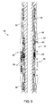
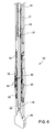
- Figure 5 illustrates an enlarged view of the steerable assembly 50.
- Figure 5 illustrates the slip ring assembly 70, the control valve assembly 80, and the pump assembly 90 disposed within the outer housing 58 that supports the bias pads 54.
- the drive shaft 55 extends through the slip ring assembly 70, the control valve assembly 80, the pump assembly 90, and the outer housing 58.
- Figure 6 illustrates the steerable assembly 50 coupled to the control collar 40 by one or more threaded tubular connections.
- the control collar 40 encloses the control module 41, a power supply 44 (such as a battery), and the electrical connector 57 for controlling and continuously monitoring the operation of the system 100.
- the control module 41 is operable to maintain the rotary steerable drilling system 100 in a substantially vertical wellbore drilling path. While drilling a vertical wellbore, if the system 100 begins to deviate from the vertical path (due to the wellbore formation characteristics for example), then the control module 41 is configured to sense the deviation and actuate the bias pad 54 as necessary to direct the system 100 back to the vertical wellbore path trajectory.
- the control module 41 includes at least two accelerometers mounted about 180 degrees apart within the control collar 40, which are configured to identify the "highside" of the wellbore when deviated from vertical.
- the highside of the wellbore is the side of the wellbore circumference at a specific point along the wellbore that is closest to the surface when the wellbore deviates from vertical.
- the system 100 is forced via the bias pads 54 toward the opposite, lowside of the wellbore to push the system 100 back to the vertical drilling path.
- the sinusoidal outputs of the accelerometers may be communicated to the control module 41, which may use the outputs to calculate and determine where the wellbore is relative to gravity.
- the control module 41 determines where each bias pad 54 is located relative to the highside of the wellbore. To determine the position of each bias pad 54, the control module 41 receives a signal from a sensor 42 (illustrated in Figures 4A , 4B , and 5 ) that is coupled to the rotating drive shaft 55. The sensor 42 rotates with the drive shaft 55 and senses at least one stationary marker 43 (illustrated in Figure 5 ) that is coupled to the outer housing 58. Only one stationary marker 43 may be needed to identify the location of one bias pad 54, while the locations of the other bias pads 54 can be determined by being disposed about 120 degrees and about 240 degrees apart from the one bias pad 54 and/or stationary marker 43.
- the sensor 42 As the sensor 42 rotates, it senses the location of each marker 43 and thus each bias pad 54 and communicates the location to the control module 41.
- the sensor 42 may include a Hall Effect device as known in the art that produces an electronic pulse once per revolution to sense and measure the location of the markers 43, which information is communicated to the control module 41 to calculate and define the rotational position of each bias pad 54 relative to the highside of the wellbore.
- the control module 41 can determine which solenoid valves of the control valve system 80 to activate to force or push the system 100 back to vertical.
- the control module 41 controls the force applied to each specific bias pad 54 by controlling the actuation of the solenoid valves of the control valve assembly 80 for each bias pad 54 to direct the system 100 toward the opposite, lowside of the wellbore and back to the vertical drilling path.
- the control module 41 can vary the amount of force applied by each bias pad 54 by controlling the amount of current supplied to the solenoid valves of the control valve assembly 80 for each individual bias pad 54.
- Figure 7 illustrates an electric/hydraulic schematic of the system 100.
- the control module 41 is electrically connected to the solenoid valves of the control valve assembly 80 via the slip ring assembly 70.
- the control valve assembly 80 may control the fluid flow through the inlet and outlet flow passages 83, 84 to control the amount of fluid pressure applied to each bias pad piston 59.
- the pump assembly 90 continuously pumps fluid through the system 100 while the drive shaft 55 rotates the drill bit 60. Fluid may be drawn from a reservoir 95 disposed in the outer housing 58.
- the accumulator system 120 may be operable to dampen rapid fluid pressure fluctuations in the system 100 to ensure that a smooth and constant force is applied to each piston 59 of each bias pad 54.
- the drill bit 60 of the rotary steerable drilling system 100 may be rotated from the surface via the drill string 10 and/or downhole by the hydraulically actuated motor 20 to drill a vertical wellbore. Rotation is transmitted to the control collar 40, the steerable assembly 50, and the drill bit 60.
- the drive shaft 55 extends through the non-rotating outer housing 58 and rotates the drill bit 60.
- the control module 41 in the control collar 40 continuously monitors and measures the vertical trajectory of the wellbore using one or more sensors, such as accelerometers. In the event that the system 100 begins to deviate from vertical, the control module 41 determines the direction of deviation by measuring the highside of the wellbore.
- the one or more sensors 42 continuously monitor and measure the locations of each bias pad 54 and transmit the information to the control module 41 via the slip ring assembly 70. Based on the locations of the bias pads 54 relative to the highside of the wellbore, the control module 41 actuates one or more of the solenoid valves of the control valve assembly 80 to control the amount of fluid pressure applied to the pistons 59 of each bias pad 54.
- the piston/cylinders 92 of the pump assembly 90 are continuously stroked by rotation of the drive shaft 55 to drive pressurized fluid to the pistons 59 of each bias pad 54.
- the amount of fluid pressure applied to each bias pad 54 is controlled by the solenoid valves of the control valve assembly 80.
- the control valve assembly 80 either allows fluid flow, prevents fluid flow, or at least partially inhibits fluid flow through the inlet and outlet flow passages 83, 84. Inhibiting or preventing fluid flow through the inlet flow passage 83 controls and increases the amount of fluid pressure applied to the pistons 59 of each bias pad 54.
- the control module 41 will control the actuation of each solenoid valve to obtain the requisite amount of bias force from each bias pad 54 to force or push the drill bit 60 back to the vertical drilling path trajectory.
- the system 100 is operable to continuously monitor the vertical drilling path trajectory and the position of each bias pad 54 relative to the wellbore.
- the system 100 is further operable to self adjust its trajectory when deviated from vertical.
- the system 100 may communicate its operational characteristics (rotational speed, inclination, etc.) to the surface via hydraulic (mud pulse) telemetry or other communication mechanisms known in the art.
Landscapes
- Engineering & Computer Science (AREA)
- Geology (AREA)
- Mining & Mineral Resources (AREA)
- Life Sciences & Earth Sciences (AREA)
- Physics & Mathematics (AREA)
- General Life Sciences & Earth Sciences (AREA)
- Fluid Mechanics (AREA)
- Environmental & Geological Engineering (AREA)
- Geochemistry & Mineralogy (AREA)
- Remote Sensing (AREA)
- Geophysics (AREA)
- Mechanical Engineering (AREA)
- General Physics & Mathematics (AREA)
- Earth Drilling (AREA)
- Processing Of Stones Or Stones Resemblance Materials (AREA)
Priority Applications (1)
| Application Number | Priority Date | Filing Date | Title |
|---|---|---|---|
| EP16168545.8A EP3103957A3 (fr) | 2013-03-12 | 2014-03-05 | Systeme rotatif orientable pour forage vertical |
Applications Claiming Priority (1)
| Application Number | Priority Date | Filing Date | Title |
|---|---|---|---|
| US13/797,875 US20140262507A1 (en) | 2013-03-12 | 2013-03-12 | Rotary steerable system for vertical drilling |
Related Child Applications (1)
| Application Number | Title | Priority Date | Filing Date |
|---|---|---|---|
| EP16168545.8A Division EP3103957A3 (fr) | 2013-03-12 | 2014-03-05 | Systeme rotatif orientable pour forage vertical |
Publications (2)
| Publication Number | Publication Date |
|---|---|
| EP2796659A2 true EP2796659A2 (fr) | 2014-10-29 |
| EP2796659A3 EP2796659A3 (fr) | 2015-11-11 |
Family
ID=50230958
Family Applications (2)
| Application Number | Title | Priority Date | Filing Date |
|---|---|---|---|
| EP16168545.8A Withdrawn EP3103957A3 (fr) | 2013-03-12 | 2014-03-05 | Systeme rotatif orientable pour forage vertical |
| EP14157833.6A Withdrawn EP2796659A3 (fr) | 2013-03-12 | 2014-03-05 | Système rotatif orientable pour forage vertical |
Family Applications Before (1)
| Application Number | Title | Priority Date | Filing Date |
|---|---|---|---|
| EP16168545.8A Withdrawn EP3103957A3 (fr) | 2013-03-12 | 2014-03-05 | Systeme rotatif orientable pour forage vertical |
Country Status (4)
| Country | Link |
|---|---|
| US (2) | US20140262507A1 (fr) |
| EP (2) | EP3103957A3 (fr) |
| BR (1) | BR102014005625A8 (fr) |
| CA (2) | CA2942125A1 (fr) |
Cited By (2)
| Publication number | Priority date | Publication date | Assignee | Title |
|---|---|---|---|---|
| CN105275397A (zh) * | 2015-10-27 | 2016-01-27 | 西南石油大学 | 一种遥控可变径稳定器 |
| EP3103957A2 (fr) | 2013-03-12 | 2016-12-14 | Weatherford Technology Holdings, LLC | Systeme rotatif orientable pour forage vertical |
Families Citing this family (26)
| Publication number | Priority date | Publication date | Assignee | Title |
|---|---|---|---|---|
| US10401512B1 (en) * | 2014-04-08 | 2019-09-03 | Pioneer Natural Resources Usa, Inc. | Microseismic density volume estimation |
| US10605005B2 (en) | 2014-12-09 | 2020-03-31 | Schlumberger Technology Corporation | Steerable drill bit system |
| US9951562B2 (en) * | 2015-01-27 | 2018-04-24 | Nabors Lux 2 | Method and apparatus for orienting a downhole tool |
| US10472955B2 (en) | 2015-01-27 | 2019-11-12 | Nabors Lux 2 Sarl | Method of providing continuous survey data while drilling |
| DE112015006191T5 (de) * | 2015-02-19 | 2017-10-26 | Halliburton Energy Services, Inc. | Gammaerfassungssensoren in einem lenkbaren Drehwerkzeug |
| DE112017000311T5 (de) * | 2016-01-08 | 2018-09-27 | Sanvean Technologies Llc | Bohrlochwerkzeug zur vertikalen und direktionalen Steuerung |
| WO2017172563A1 (fr) | 2016-03-31 | 2017-10-05 | Schlumberger Technology Corporation | Direction et communication de train de tiges d'équipement |
| US10415363B2 (en) | 2016-09-30 | 2019-09-17 | Weatherford Technology Holdings, Llc | Control for rotary steerable system |
| US10364608B2 (en) | 2016-09-30 | 2019-07-30 | Weatherford Technology Holdings, Llc | Rotary steerable system having multiple independent actuators |
| CN106368624B (zh) * | 2016-10-10 | 2018-12-07 | 东北石油大学 | 一种平衡钻压微调角度装置 |
| US10287821B2 (en) | 2017-03-07 | 2019-05-14 | Weatherford Technology Holdings, Llc | Roll-stabilized rotary steerable system |
| GB201705424D0 (en) | 2017-04-04 | 2017-05-17 | Schlumberger Technology Bv | Steering assembly |
| US10641077B2 (en) | 2017-04-13 | 2020-05-05 | Weatherford Technology Holdings, Llc | Determining angular offset between geomagnetic and gravitational fields while drilling wellbore |
| WO2018212754A1 (fr) | 2017-05-15 | 2018-11-22 | Halliburton Energy Services, Inc. | Système orientable rotatif actionné par boue à boîtier roulant |
| US10683702B2 (en) * | 2017-10-29 | 2020-06-16 | Weatherford Technology Holdings, Llc | Rotary steerable system having actuator with linkage |
| CN108005580B (zh) * | 2017-12-29 | 2023-10-20 | 中国地质大学(北京) | 一种在垂直姿态下零造斜的静态机械式自动垂直钻具 |
| US10858934B2 (en) | 2018-03-05 | 2020-12-08 | Baker Hughes, A Ge Company, Llc | Enclosed module for a downhole system |
| US11230887B2 (en) * | 2018-03-05 | 2022-01-25 | Baker Hughes, A Ge Company, Llc | Enclosed module for a downhole system |
| US11434696B2 (en) | 2018-07-02 | 2022-09-06 | Schlumberger Technology Corporation | Directional drilling systems and methods |
| US11021912B2 (en) * | 2018-07-02 | 2021-06-01 | Schlumberger Technology Corporation | Rotary steering systems and methods |
| US11118406B2 (en) | 2018-07-02 | 2021-09-14 | Schlumberger Technology Corporation | Drilling systems and methods |
| CN110863817B (zh) * | 2019-12-03 | 2020-07-21 | 西南石油大学 | 一种超声波井眼防碰监测系统及监测方法 |
| CN114876360B (zh) * | 2022-04-14 | 2025-01-24 | 中国石油大学(华东) | 基于垂直钻井系统的新型钻具组合及钻进参数优化方法 |
| CN115434968B (zh) * | 2022-08-31 | 2025-05-13 | 西南石油大学 | 一种泥浆驱动旋转导向钻井控制系统 |
| CN120649801B (zh) * | 2025-07-25 | 2026-03-20 | 山东科技大学 | 千米定向钻用的复合式钻杆自动纠偏导向装置及方法 |
| CN121228980B (zh) * | 2025-12-02 | 2026-02-24 | 四川路桥盛通建筑工程有限公司 | 一种斜坡土层钻进装置 |
Family Cites Families (25)
| Publication number | Priority date | Publication date | Assignee | Title |
|---|---|---|---|---|
| US3691363A (en) | 1970-07-17 | 1972-09-12 | Texaco Inc | Method and apparatus for bore hole directional logging |
| US3741717A (en) | 1971-12-27 | 1973-06-26 | L Triplett | Grain treating apparatuses and processes of operation thereof |
| US4761889A (en) | 1984-05-09 | 1988-08-09 | Teleco Oilfield Services Inc. | Method for the detection and correction of magnetic interference in the surveying of boreholes |
| GB9204910D0 (en) * | 1992-03-05 | 1992-04-22 | Ledge 101 Ltd | Downhole tool |
| US6047784A (en) | 1996-02-07 | 2000-04-11 | Schlumberger Technology Corporation | Apparatus and method for directional drilling using coiled tubing |
| DE19607402C1 (de) | 1996-02-28 | 1997-07-10 | Welldone Engineering Gmbh | Vorrichtung zum Übertragen von Informationen innerhalb eines Bohrrohrstranges einer Bohrvorrichtung mittels Druckimpulsen in einer strömenden Flüssigkeit, insbesondere Bohrspülflüssigkeit |
| EP0954674B1 (fr) * | 1997-01-30 | 2001-09-12 | Baker Hughes Incorporated | Ensemble de forage avec dispositif de guidage pour operations effectuees avec des colonnes de production spiralees |
| GB2356207A (en) * | 1999-11-09 | 2001-05-16 | Stephen John Mcloughlin | Apparatus and method for transmitting information to, and communicating with, a downhole device. |
| CA2474228C (fr) | 1999-07-12 | 2008-03-11 | Halliburton Energy Services, Inc. | Methode de forage dirige pour dispositif de forage rotatif orientable |
| DE19950040A1 (de) | 1999-10-16 | 2001-05-10 | Dmt Welldone Drilling Services | Vorrichtung zum Niederbringen verlaufkontrollierter Bohrungen |
| DE69930043T2 (de) | 1999-12-08 | 2007-03-08 | Services Petroliers Schlumberger | Vorrichtung und Verfahren zum Steuern eines Richtbohrwerkzeugs |
| US6427783B2 (en) * | 2000-01-12 | 2002-08-06 | Baker Hughes Incorporated | Steerable modular drilling assembly |
| US6808027B2 (en) | 2001-06-11 | 2004-10-26 | Rst (Bvi), Inc. | Wellbore directional steering tool |
| US7556105B2 (en) * | 2002-05-15 | 2009-07-07 | Baker Hughes Incorporated | Closed loop drilling assembly with electronics outside a non-rotating sleeve |
| WO2004072682A1 (fr) * | 2003-02-11 | 2004-08-26 | Noble Drilling Services, Inc. | Source d'energie sismique a utiliser pendant le forage d'un puits |
| FR2859750B1 (fr) * | 2003-09-15 | 2006-10-20 | Cie Du Sol | Installation de forage a tete rotative |
| GB2408526B (en) * | 2003-11-26 | 2007-10-17 | Schlumberger Holdings | Steerable drilling system |
| US7708086B2 (en) * | 2004-11-19 | 2010-05-04 | Baker Hughes Incorporated | Modular drilling apparatus with power and/or data transmission |
| US7426967B2 (en) * | 2005-11-14 | 2008-09-23 | Pathfinder Energy Services, Inc. | Rotary steerable tool including drill string rotation measurement apparatus |
| US20110284292A1 (en) * | 2009-02-26 | 2011-11-24 | Halliburton Energy Services, Inc. | Apparatus and Method for Steerable Drilling |
| US8689905B2 (en) * | 2009-11-24 | 2014-04-08 | Baker Hughes Incorporated | Drilling assembly with steering unit integrated in drilling motor |
| US9273522B2 (en) * | 2011-10-14 | 2016-03-01 | Baker Hughes Incorporated | Steering head with integrated drilling dynamics control |
| US9982525B2 (en) | 2011-12-12 | 2018-05-29 | Schlumberger Technology Corporation | Utilization of dynamic downhole surveying measurements |
| WO2013109278A1 (fr) | 2012-01-19 | 2013-07-25 | Halliburton Energy Services, Inc. | Appareil, systèmes, et procédés de détection magnétique |
| US20140262507A1 (en) | 2013-03-12 | 2014-09-18 | Weatherford/Lamb, Inc. | Rotary steerable system for vertical drilling |
-
2013
- 2013-03-12 US US13/797,875 patent/US20140262507A1/en not_active Abandoned
-
2014
- 2014-03-04 CA CA2942125A patent/CA2942125A1/fr not_active Abandoned
- 2014-03-04 CA CA2844572A patent/CA2844572A1/fr not_active Abandoned
- 2014-03-05 EP EP16168545.8A patent/EP3103957A3/fr not_active Withdrawn
- 2014-03-05 EP EP14157833.6A patent/EP2796659A3/fr not_active Withdrawn
- 2014-03-11 BR BR102014005625A patent/BR102014005625A8/pt not_active IP Right Cessation
-
2016
- 2016-06-06 US US15/174,233 patent/US20160349082A1/en not_active Abandoned
Non-Patent Citations (1)
| Title |
|---|
| None |
Cited By (2)
| Publication number | Priority date | Publication date | Assignee | Title |
|---|---|---|---|---|
| EP3103957A2 (fr) | 2013-03-12 | 2016-12-14 | Weatherford Technology Holdings, LLC | Systeme rotatif orientable pour forage vertical |
| CN105275397A (zh) * | 2015-10-27 | 2016-01-27 | 西南石油大学 | 一种遥控可变径稳定器 |
Also Published As
| Publication number | Publication date |
|---|---|
| US20160349082A1 (en) | 2016-12-01 |
| BR102014005625A8 (pt) | 2016-02-10 |
| EP2796659A3 (fr) | 2015-11-11 |
| EP3103957A2 (fr) | 2016-12-14 |
| CA2844572A1 (fr) | 2014-09-12 |
| US20140262507A1 (en) | 2014-09-18 |
| CA2942125A1 (fr) | 2014-09-12 |
| BR102014005625A2 (pt) | 2015-02-03 |
| EP3103957A3 (fr) | 2017-03-22 |
Similar Documents
| Publication | Publication Date | Title |
|---|---|---|
| EP2796659A2 (fr) | Système rotatif orientable pour forage vertical | |
| EP2859171B1 (fr) | Actionneurs orientables rotatifs modulaires, outil d'orientation, et systèmes de forage orientables rotatifs comportant des actionneurs modulaires | |
| US6913095B2 (en) | Closed loop drilling assembly with electronics outside a non-rotating sleeve | |
| US7556105B2 (en) | Closed loop drilling assembly with electronics outside a non-rotating sleeve | |
| US7306060B2 (en) | Drilling assembly with a steering device for coiled-tubing operations | |
| US9145736B2 (en) | Tilted bit rotary steerable drilling system | |
| US9284782B2 (en) | Eccentric steering device and methods of directional drilling | |
| US11624237B2 (en) | Rotary steerable tool with proportional control valve | |
| US7287605B2 (en) | Steerable drilling apparatus having a differential displacement side-force exerting mechanism | |
| US20100139980A1 (en) | Ball piston steering devices and methods of use | |
| CN108431363A (zh) | 旋转导向钻井工具 | |
| US8567528B2 (en) | Apparatus and method for directional drilling | |
| US12060792B2 (en) | Rotary steerable drilling tool and method with independently actuated pads | |
| AU2017355273B2 (en) | Flexible collar for a rotary steerable system | |
| CN108431360A (zh) | 使用动态可调节可变排量泵的井下动力转换和管理 | |
| CA2873643A1 (fr) | Appareil et procede permettant de commander une partie d'un ensemble fond de trou et ensemble fond de trou | |
| WO2008004999A1 (fr) | Ensemble de forage en boucle fermée avec des composants électroniques à l'extérieur d'un manchon non rotatif |
Legal Events
| Date | Code | Title | Description |
|---|---|---|---|
| PUAI | Public reference made under article 153(3) epc to a published international application that has entered the european phase |
Free format text: ORIGINAL CODE: 0009012 |
|
| 17P | Request for examination filed |
Effective date: 20140305 |
|
| AK | Designated contracting states |
Kind code of ref document: A2 Designated state(s): AL AT BE BG CH CY CZ DE DK EE ES FI FR GB GR HR HU IE IS IT LI LT LU LV MC MK MT NL NO PL PT RO RS SE SI SK SM TR |
|
| AX | Request for extension of the european patent |
Extension state: BA ME |
|
| PUAL | Search report despatched |
Free format text: ORIGINAL CODE: 0009013 |
|
| AK | Designated contracting states |
Kind code of ref document: A3 Designated state(s): AL AT BE BG CH CY CZ DE DK EE ES FI FR GB GR HR HU IE IS IT LI LT LU LV MC MK MT NL NO PL PT RO RS SE SI SK SM TR |
|
| AX | Request for extension of the european patent |
Extension state: BA ME |
|
| RIC1 | Information provided on ipc code assigned before grant |
Ipc: E21B 44/00 20060101ALI20151002BHEP Ipc: E21B 7/06 20060101ALI20151002BHEP Ipc: E21B 17/10 20060101ALI20151002BHEP Ipc: E21B 7/10 20060101AFI20151002BHEP |
|
| RAP1 | Party data changed (applicant data changed or rights of an application transferred) |
Owner name: WEATHERFORD TECHNOLOGY HOLDINGS, LLC |
|
| STAA | Information on the status of an ep patent application or granted ep patent |
Free format text: STATUS: THE APPLICATION IS DEEMED TO BE WITHDRAWN |
|
| 18D | Application deemed to be withdrawn |
Effective date: 20160512 |