EP2796764B1 - Dispositif pour l'entretien des réservoirs cryogéniques isolés par vide - Google Patents
Dispositif pour l'entretien des réservoirs cryogéniques isolés par vide Download PDFInfo
- Publication number
- EP2796764B1 EP2796764B1 EP13165564.9A EP13165564A EP2796764B1 EP 2796764 B1 EP2796764 B1 EP 2796764B1 EP 13165564 A EP13165564 A EP 13165564A EP 2796764 B1 EP2796764 B1 EP 2796764B1
- Authority
- EP
- European Patent Office
- Prior art keywords
- plug
- fitting
- actuator
- transparent
- vacuum
- Prior art date
- Legal status (The legal status is an assumption and is not a legal conclusion. Google has not performed a legal analysis and makes no representation as to the accuracy of the status listed.)
- Active
Links
Images


Classifications
-
- F—MECHANICAL ENGINEERING; LIGHTING; HEATING; WEAPONS; BLASTING
- F17—STORING OR DISTRIBUTING GASES OR LIQUIDS
- F17C—VESSELS FOR CONTAINING OR STORING COMPRESSED, LIQUEFIED OR SOLIDIFIED GASES; FIXED-CAPACITY GAS-HOLDERS; FILLING VESSELS WITH, OR DISCHARGING FROM VESSELS, COMPRESSED, LIQUEFIED, OR SOLIDIFIED GASES
- F17C13/00—Details of vessels or of the filling or discharging of vessels
-
- F—MECHANICAL ENGINEERING; LIGHTING; HEATING; WEAPONS; BLASTING
- F17—STORING OR DISTRIBUTING GASES OR LIQUIDS
- F17C—VESSELS FOR CONTAINING OR STORING COMPRESSED, LIQUEFIED OR SOLIDIFIED GASES; FIXED-CAPACITY GAS-HOLDERS; FILLING VESSELS WITH, OR DISCHARGING FROM VESSELS, COMPRESSED, LIQUEFIED, OR SOLIDIFIED GASES
- F17C2203/00—Vessel construction, in particular walls or details thereof
- F17C2203/03—Thermal insulations
- F17C2203/0391—Thermal insulations by vacuum
-
- F—MECHANICAL ENGINEERING; LIGHTING; HEATING; WEAPONS; BLASTING
- F17—STORING OR DISTRIBUTING GASES OR LIQUIDS
- F17C—VESSELS FOR CONTAINING OR STORING COMPRESSED, LIQUEFIED OR SOLIDIFIED GASES; FIXED-CAPACITY GAS-HOLDERS; FILLING VESSELS WITH, OR DISCHARGING FROM VESSELS, COMPRESSED, LIQUEFIED, OR SOLIDIFIED GASES
- F17C2221/00—Handled fluid, in particular type of fluid
- F17C2221/01—Pure fluids
- F17C2221/011—Oxygen
-
- F—MECHANICAL ENGINEERING; LIGHTING; HEATING; WEAPONS; BLASTING
- F17—STORING OR DISTRIBUTING GASES OR LIQUIDS
- F17C—VESSELS FOR CONTAINING OR STORING COMPRESSED, LIQUEFIED OR SOLIDIFIED GASES; FIXED-CAPACITY GAS-HOLDERS; FILLING VESSELS WITH, OR DISCHARGING FROM VESSELS, COMPRESSED, LIQUEFIED, OR SOLIDIFIED GASES
- F17C2223/00—Handled fluid before transfer, i.e. state of fluid when stored in the vessel or before transfer from the vessel
- F17C2223/01—Handled fluid before transfer, i.e. state of fluid when stored in the vessel or before transfer from the vessel characterised by the phase
- F17C2223/0146—Two-phase
- F17C2223/0153—Liquefied gas, e.g. LPG, GPL
- F17C2223/0161—Liquefied gas, e.g. LPG, GPL cryogenic, e.g. LNG, GNL, PLNG
-
- F—MECHANICAL ENGINEERING; LIGHTING; HEATING; WEAPONS; BLASTING
- F17—STORING OR DISTRIBUTING GASES OR LIQUIDS
- F17C—VESSELS FOR CONTAINING OR STORING COMPRESSED, LIQUEFIED OR SOLIDIFIED GASES; FIXED-CAPACITY GAS-HOLDERS; FILLING VESSELS WITH, OR DISCHARGING FROM VESSELS, COMPRESSED, LIQUEFIED, OR SOLIDIFIED GASES
- F17C2260/00—Purposes of gas storage and gas handling
- F17C2260/01—Improving mechanical properties or manufacturing
- F17C2260/015—Facilitating maintenance
Definitions
- the present invention relates to a device for the maintenance of cryogenic containers.
- the present invention relates to an actuator device for the closing system which closes the interspace of a cryogenic container, for example of the type used for liquefied gases.
- cryogenic containers is intended to mean any structure in which a wall, generally the external one, is provided with an interspace in which a vacuum is created in order to thermally insulate the content thereof from the external environment; particularly, such a definition is intended to encompass both movable cryogenic containers of the Dewar type which are used for the transportation of liquefied gases such as oxygen and cryogenic liquefied gases in general, and fixed structures such as pipings or other structures (e.g., containers, dispensers, tanks) which either contain or are passed through by liquefied cryogenic gases.
- the interspace is provided with an opening and a closing system therefor which comprises a protruding cylindrical portion to which the pipe leading to the vacuum pump is fastened, and a member acting as a closing plug to close the opening.
- a closing system for the interspace is known as a "vacuum port" in the art.
- this plug - housing assembly will be referred to as a "closing system for the container".
- Cryogenic containers require maintenance and particularly periodic inspection and restoring the vacuum within the interspace as needed.
- the plug is removed from its housing on the container and the interspace of the container is connected to the vacuum pump, preferably without bringing the interspace to ambient pressure because of the long time required to bring it back to the requisite value of vacuum.
- an actuator device (also referred to as a "gun") which allows the plug to be removed and repositioned and the interspace to be connected to the vacuum source without losing the residual vacuum existing within the interspace;
- the actuator device comprises a generally cylindrical body which is provided with a tubular side fitting for the connection to the vacuum pump; the cylindrical body has accommodated therein a movable rod which can engage with the plug arranged on the outlet of the container interspace in order to pull it out and move it back at the end of the restoring process.
- a problem with the actuators known in the art is that they are entirely made of metal, thereby preventing the user from observing the position of the plug with respect to either its housing on the container or the fitting leading to the vacuum pump; furthermore, conventional actuators prevent the user from visually checking the conditions of the sealing gasket on the plug in order to determine whether the gasket has to be replaced.
- actuators i.e. guns
- the cylindrical body is made of a transparent plastic material, particularly Plexiglas, so as to allow the position of the plug and the conditions of the gasket to be checked.
- a material i.e. plastic, which is partially permeable to gases and also likely to develop cracks and breaks in the device body with use.
- US 3364649 discloses an apparatus for sealing vacuum enclosures, comprising a transparent glass evacuation chamber.
- An external gasket may be clamped onto the lower portion of the transparent chamber to allow connection with the enclosure.
- the transparent chamber is also provided with a duct that may be connected to a vacuum source.
- the shape of the transparent chamber is quite complex to realize, and shaping fittings with precision in glass is very expensive.
- the aim of the present invention is to solve the above mentioned problems by providing an actuator device for closing systems for a container, being able to be sealed and allowing the gasket of the plug of the closing system to be checked, thereby reducing time and costs for the container maintenance.
- This aim is achieved by the present invention which provides an actuator device for closing systems for interspaces in containers for cryogenic gases, said closing system comprising a plug and a seat for said plug, wherein said actuator device comprises:
- the actuator acts on the closing system for the vacuum interspace of a cryogenic container
- the closing system comprises a plug and a seat for the plug, such a seat being externally engaged by the first fitting of the actuator device.
- the body of the actuator device is at least partially hollow and, as known in the art, it is provided with a rod axially movable through one end of the body, i.e. through one side of the actuator device, and whose length is sufficient to reach at least the opposite end of said body, and which is provided with means for the engagement with the plug of the closing system; a second tubular fitting is also provided for the connection to a vacuum source, such a second fitting being fastened to the side of the body at said hollow part of said body.
- the tubular body of the actuator device comprises a metal portion and a transparent material portion which can be sealingly constrained to each other, both the first and second fittings are advantageously fastened to the metal portion of said tubular body, whereas the mentioned end wall passed through by the rod is part of the transparent material portion of the tubular body.
- the first fitting can be removed and/ or replaced with a different fitting.
- the second fitting is a tubular pipe whose diameter is substantially equal to that of the pipe leading to said vacuum pump.
- the distance between the second fitting and the end of the metal body which is adjacent to the transparent body may be such that said plug can be housed therein; in this case, the sizes, namely the internal diameter, of this part of the metal body are such that the plug can be sealingly housed within said portion so as to confine the vacuum only to the metal part of the device.
- the metal portion and the transparent portion of the tubular body are constrained to each other by reversible means, such as screws or the like, which allow for the replacement of sealing gaskets interposed therebetween.
- the device comprises a slide valve or the like to temporarily close the interspace of the container while the gasket on the plug is being replaced, thereby preventing the residual vacuum in said interspace from being lost.
- the invention further concerns a process for the maintenance of cryogenic containers by the removal of the plug of the closing system for said container and the connection of the interspace of said container to a vacuum source, characterized by using an actuator of the afore described type for the removal of said plug, said plug being passed through a metal portion of the body of said actuator until it reaches a transparent portion of said actuator in order to allow said plug to be visually inspected.
- the hollow part of said body extends through said metal portion of the tubular body and through part of the transparent material portion of the body, and has a size sufficient to allow said plug to be moved within said transparent part for the inspection thereof.
- the invention presents a number of advantages relative to the known art.
- the presence of a metal portion of the body to which the two fittings for the connection to both the vacuum pump and the closing system of the container are constrained can provide a structure which is solid and impermeable to gases, without sealing problems for the fittings on the tubular body as well as without cracking problems.
- the condition of the gasket of the plug can be visually inspected by positioning it at the transparent material portion of the body of the device, the condition of the gasket on the plug can be checked in a simple and reliable manner.
- a further advantage is that the fitting for the connection to the vacuum pump can be dimensioned in such a way that the diameter of the fitting is equal or similar to that of the pipe of the pump, thereby preventing the vacuum line from being restricted.
- the plug can be (at least partially) sealingly positioned within the cavity formed in the metal portion of the cylindrical body after the inspection thereof, so as to be able to confine the vacuum only to the metal part of the device during the vacuum restoring process.
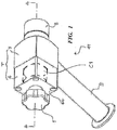
- an actuator device 11 which comprises a knob 1, a tubular body T composed of a metal portion 7 and a transparent portion 4 generally made of a transparent plastic material such as, for example, polycarbonate or the like.
- a tubular body T composed of a metal portion 7 and a transparent portion 4 generally made of a transparent plastic material such as, for example, polycarbonate or the like.
- the two portions 4 and 7 of the body T are constrained to each other so as to form a sealing body T.
- a first axial fitting 8 and a second side tubular fitting 9, which are both made of a metal, e.g. steel, as is the portion 7 of the body T, are provided for the metal portion 7 in a way known in the art, for example by welding.
- the two portions 4 and 7 are internally hollow.
- the knob 1 is constrained to a rod 2 which can be rotated together with the knob 1 and axially moved within the portion 4 and portion 7 of the tubular body T ( Figs. 4 and 5 ).
- the upper end 2a of the rod 2 is housed within the knob 1, and the latter is constrained to the rod so as to allow the rod to be both rotated about its axis A-A and translationally moved therealong within the tubular body T.
- the length of the rod 2 is such that it can reach at least the opposite end of the metal portion 7 of the tubular body T; in such a way, the lower end 2b of the rod 2, which is threaded, can be engaged with a corresponding internal thread (not shown) formed in the sealing plug 13 of the container ( Figs. 4-5 ) through a rotational movement of the knob 1.
- the portion 4 which is made of a transparent material, generally a plastic such as polycarbonate; such a portion is provided with an internal cylindrical cavity C1 having size sufficient to freely accommodate the plug 13 of the container when the gasket 16 thereof is being visually inspected.
- the cavity C1 defines a wall 4a.
- the rod 2 is sealingly slidable within a hole 4c obtained through the wall 4a of the portion 4 of the body T and the seal between the rod 2 and the wall of the hole 4c is made by means of one or more gaskets; in the embodiment shown herein, there are three gaskets 3 of O-ring type which are identical in size and housed within three grooves 17 intended to accommodate them.
- the wall 4a of the portion 4 is provided with four fastening holes 12 at the corners, said holes being intended to accommodate constraining means, such as sealing screws or the like (not shown), in order to fasten the transparent portion 4 to the metal portion 7.
- the portion 4 Since the portion 4 is made of a transparent material, it enables the position of the sealing plug 13 ( Fig. 5 ) to be checked directly once it has been removed from the container 15, and to determine whether the sealing gasket 16 accommodated therein, generally of an O-ring type, has to be replaced due to wear.
- the plug 13 provided with the sealing gasket 16 is usually positioned in a known way ( Fig. 4 ) within the seat 14 acting as a connector to the interspace of the container 15, which is under a high vacuum.
- the plug 13 is provided with means, such as an internal thread, adapted to be engaged by the end of the rod 2 in a known manner.
- a cylindrical-shaped step protrudes from the lower surface of the portion 4 for the engagement with a corresponding step formed in the front part of the portion 7.
- the metal portion 7 has an internal cylindrical-shaped cavity C2 whose size is equal to that of the cavity C1 and in any case sufficient to allow the plug 13 to be passed therethrough before the inspection and then housed therein after the inspection.
- Two grooves or housings 7b are obtained in the upper surface 7a of the portion 7 in order to accommodate the gaskets 5-6 which provide the seal between the two portions of the tubular body T.
- the gaskets 5-6 have two different diameters which are equal to those of the corresponding grooves 7b in which the gaskets are housed, thereby providing a seal between the portion 7 and the protruding step of the portion 4.
- the lower surface of the portion 7 has welded thereto an annular nut 7d for the engagement with the cylindrical-shaped sealing fitting 8 ( Fig. 2 ) with the aid of a pair of sealing gaskets 6a, usually of an O-ring type; the gaskets 6a may be identical in diameter to the gasket 6.
- the sealing fitting 8 is required to ensure the engagement of the actuator device 11 with the closing system of the container 15.
- Such a closing system comprises ( Figs. 4-5 ) a sealing plug 13 and a cylindrical-shaped seat 14 intended to house the sealing plug 13; the seat 14 also acts as a connector to which the "gun", i.e. the actuator device according to the invention, is mounted.
- the plug 13 is characterized by an internal thread (not shown) intended to be engaged with the end 2b of the rod 2 ( Fig. 2 ) and it is externally provided with a sealing gasket 16, for example of an O-ring type.
- the plug is slid through the cavity C2 and along the axis A-A until it reaches the cavity C1 ( Fig. 5 ), where the visual inspection occurs.
- the sealing fitting 8 is internally engaged with the seat 14 of the sealing plug 13 of the cryogenic container 15. Furthermore, the fitting 8 can be removed and/ or replaced with another fitting which is similar in shape but different in size according to the diameter required for the outlet to properly engage with the seat 14 of the plug.
- the fitting 9 is a tubular pipe whose diameter is substantially equal to that of the hose of the pump (not shown), thereby preventing the operation of the pump from being restricted.
- the fitting 9 is welded to the portion 7 in such a way that the axis of the fitting 9 forms an angle in the range from 35 to 55°, more preferably of about 45°, with the axis A-A of the tubular body (which is coaxial with the rod 2).
- the fitting 9 is welded at the cavity C2 of the metal part 7 of the tubular body T.
- the free end of the fitting 9, which is directed towards the pump, has a steel flange 10 to facilitate the connection and release of the device to/ from the pump, for example in order to clean the device 11.
- the embodiment illustrated in Fig. 6 shows an embodiment of a device in which the distance between the weld root 18 of the fitting 9 and the upper surface 7a of the portion 7 (i.e. the surface of portion 7 in contact with the transparent part 4) is such that there is a sufficient space to sealingly house the plug 13 therein after the inspection.
- the portion of the metal body 7 which is adjacent to the transparent body 4 is shaped in such a way as to be able to sealingly house the plug; therefore, the plug can take an intermediate position between the position in which the "vacuum port" of the interspace 15 is closed, and the position in which it is fully retracted into the transparent part 4 in order to allow the plug to be visually inspected.
- the plug in which the plug is sealed against the body 7, allows the vacuum to be confined to the metal part 7 of the body T.
- the metal portion 7 of the tubular body is provided with a part 17 in which the cavity C2 has a diameter which is reduced with respect to the diameter of the remainder of the cavity C2 and which can be substantially equal to the diameter of the seat 14 of the closing system for the container, such a reduced diameter being in any case sufficient to provide a sufficient seal between the plug and the part 17 of the body 7.
- said plug is sealed thereagainst preferably as if it were in the seat 14, thereby preventing the plastic part 4 of the tubular body T from being stressed by the high vacuum created by the pump.
- a slide valve (not shown) may be interposed either between the device and the closing system for the interspace of the container 15 or between two portions of the actuator device, for example between the portions 4 and 7 of the body T.
- the two portions should be releasable in order to allow the plug to be removed and the gasket to be replaced.
- the valve is closed so as to allow the interspace of the container 15 to be maintained under vacuum, thereby avoiding the need to remove the residual vacuum in order to carry out the replacement of the gasket.
- the device 11 When in operation, the device 11 is initially positioned with the fitting 8 which houses the seat 14 of the closing system for the container 15 and the second fitting which is connected to the vacuum source. Once the device is under vacuum, the rod 2 is translated until it reaches the plug 13; at this time, the rod 2 is engaged with the plug, for example, in the embodiment shown herein, the rod 2 is rotated by the knob 1 in order to screw the end of the rod into the threaded seat formed in the plug 13. As mentioned above, the cavities C1 and C2 are under vacuum.
- the rod 2 is moved back to the starting position, i.e. partially extracted from the body T, while the plug 13 is simultaneously removed from the seat 14 and moved until it reaches the cavity C1 in the transparent portion 4 of the tubular body T, adjacent to the wall 4a, as shown in Fig. 5 . Then, the plug is inspected to check the condition of the gasket 16 and, if necessary, the gasket is replaced with a new one. Thereafter, the vacuum required in the interspace is restored.
- the plug 13 is advantageously moved to the intermediate position between the two above described positions as shown in Fig. 6 , where the plug is sealingly housed within the portion 17 of the metal body 7.
- the plug is moved back to its starting position within the seat 14. Then, the gun 11 is removed from the container.
Landscapes
- Engineering & Computer Science (AREA)
- Mechanical Engineering (AREA)
- General Engineering & Computer Science (AREA)
- Pressure Vessels And Lids Thereof (AREA)
Claims (9)
- Dispositif actionneur (11) pour des systèmes de fermeture pour un conteneur cryogénique (15), comprenant :- un corps tubulaire au moins partiellement creux (T) ;- un premier raccord (8) pour la connexion à un système de fermeture, ledit système comprenant un bouchon (13) et un siège (14) pour ledit bouchon ;- une tige (2) mobile de façon axiale à travers une paroi d'extrémité (4a) dudit corps (T) et dont la longueur est suffisante pour atteindre au moins l'extrémité opposée dudit corps (T), ladite tige (2) étant munie d'un moyen pour la mise en prise avec ledit bouchon de fermeture (13) ;- un second raccord tubulaire (9) pour la connexion à une source de vide, ledit second raccord étant fixé au côté dudit corps (T) au niveau de ladite portion creuse dudit corps ;caractérisé en ce que ledit corps tubulaire (T) comprend une portion de métal (7) et une portion de matière transparente (4) qui sont contraintes l'une à l'autre de manière étanche, en ce que ledit premier raccord (8) et ledit second raccord (9) sont attachés à ladite portion de métal (7) dudit corps tubulaire (T), et en ce que ladite paroi d'extrémité à travers laquelle ladite tige passe (2) fait partie de la portion de matière transparente (4) dudit corps tubulaire (T).
- Actionneur (11) selon la revendication 1, dans lequel la partie creuse dudit corps s'étend à travers ladite portion de métal (7) du corps tubulaire (T) et à travers une partie de la portion de matière transparente (4) du corps et a une taille suffisante pour permettre audit bouchon (13) d'être traversé par cette dernière jusqu'à ce qu'il atteigne ladite portion transparente (4).
- Actionneur (11) selon la revendication 1 ou 2, dans lequel ledit premier raccord (8) peut être enlevé et/ou remplacé par un raccord différent.
- Actionneur (11) selon l'une quelconque des revendications précédentes, dans lequel ledit second raccord (9) est un tuyau tubulaire dont le diamètre est sensiblement égal à celui d'un tuyau menant à ladite pompe à vide.
- Actionneur (11) selon l'une quelconque des revendications précédentes, dans lequel la distance entre ledit second raccord (9) et l'extrémité du corps de métal (7) qui est adjacente au corps transparent (4) est telle qu'au moins une partie dudit bouchon (13) peut être logée en son sein.
- Actionneur (11) selon la revendication 5, dans lequel ladite portion (7) du corps tubulaire (T) est munie d'une partie (17) dans laquelle la cavité (C2) du corps de métal a un diamètre réduit afin de définir un joint entre le bouchon (13) et ladite partie (17) du corps (7).
- Actionneur (11) selon l'une quelconque des revendications précédentes, dans lequel ladite portion de métal (7) et ladite portion transparente (4) du corps tubulaire (T) sont contraintes l'une à l'autre par un moyen réversible comme des vis ou analogues.
- Processus pour la maintenance d'un conteneur cryogénique par l'enlèvement du bouchon (13) d'un système de fermeture pour ledit conteneur et la connexion de l'inter-espace dudit conteneur à une source de vide, caractérisé par l'utilisation d'un actionneur (11) selon l'une quelconque des revendications précédentes pour l'enlèvement dudit bouchon (13), ledit bouchon (13) étant passé à travers la portion de métal (7) du corps (T) dudit actionneur (11) jusqu'à ce qu'il atteigne la portion transparente (4) dudit actionneur (11) afin de permettre audit bouchon (13) d'être visuellement inspecté.
- Processus selon la revendication 8 dans lequel, après que ledit bouchon (13) a été inspecté, il est au moins partiellement déplacé dans la cavité (C2) formée dans ladite portion de métal (7) du corps cylindrique (T) et logé de manière étanche entre les parois de ladite cavité (C2) pendant l'étape de rétablissement de vide.
Priority Applications (2)
| Application Number | Priority Date | Filing Date | Title |
|---|---|---|---|
| EP13165564.9A EP2796764B1 (fr) | 2013-04-26 | 2013-04-26 | Dispositif pour l'entretien des réservoirs cryogéniques isolés par vide |
| ES13165564T ES2712140T3 (es) | 2013-04-26 | 2013-04-26 | Dispositivo para el mantenimiento de recipientes criogénicos aislados por vacío |
Applications Claiming Priority (1)
| Application Number | Priority Date | Filing Date | Title |
|---|---|---|---|
| EP13165564.9A EP2796764B1 (fr) | 2013-04-26 | 2013-04-26 | Dispositif pour l'entretien des réservoirs cryogéniques isolés par vide |
Publications (2)
| Publication Number | Publication Date |
|---|---|
| EP2796764A1 EP2796764A1 (fr) | 2014-10-29 |
| EP2796764B1 true EP2796764B1 (fr) | 2018-11-28 |
Family
ID=48747290
Family Applications (1)
| Application Number | Title | Priority Date | Filing Date |
|---|---|---|---|
| EP13165564.9A Active EP2796764B1 (fr) | 2013-04-26 | 2013-04-26 | Dispositif pour l'entretien des réservoirs cryogéniques isolés par vide |
Country Status (2)
| Country | Link |
|---|---|
| EP (1) | EP2796764B1 (fr) |
| ES (1) | ES2712140T3 (fr) |
Family Cites Families (5)
| Publication number | Priority date | Publication date | Assignee | Title |
|---|---|---|---|---|
| US2032862A (en) * | 1932-07-29 | 1936-03-03 | Gen Electric | Device for sealing-off metal tanks |
| US3364649A (en) * | 1963-06-28 | 1968-01-23 | Union Carbide Corp | Apparatus for sealing vacuum enclosures |
| US6568194B1 (en) * | 2001-01-17 | 2003-05-27 | Superconductor Technologies, Inc. | Evacuation port and closure for dewars |
| DE102007016974B4 (de) * | 2007-04-10 | 2017-06-22 | Bayerische Motoren Werke Aktiengesellschaft | Behältersysstem mit einer Vakuum-Isolationshülle, insbesondere Fahrzeug-Kryotank |
| CA2798864C (fr) * | 2012-12-17 | 2014-04-08 | Westport Power Inc. | Methode et appareil d'entretien d'un reservoir, d'un bouchon ou d'un reservoir et d'un bouchon |
-
2013
- 2013-04-26 ES ES13165564T patent/ES2712140T3/es active Active
- 2013-04-26 EP EP13165564.9A patent/EP2796764B1/fr active Active
Non-Patent Citations (1)
| Title |
|---|
| None * |
Also Published As
| Publication number | Publication date |
|---|---|
| EP2796764A1 (fr) | 2014-10-29 |
| ES2712140T3 (es) | 2019-05-09 |
Similar Documents
| Publication | Publication Date | Title |
|---|---|---|
| US3152452A (en) | Vacuum-insulated valved coupling | |
| KR20230130095A (ko) | 비상 해제 및 커플링 장치 | |
| US20150165461A1 (en) | Pressurized container | |
| KR101448240B1 (ko) | 진공단열배관 | |
| US11339912B2 (en) | Coupling for fluid-conducting lines | |
| US9822931B2 (en) | Method and apparatus for servicing a tank, a plug, or a tank and plug | |
| CN115151747B (zh) | 阀门 | |
| KR102195462B1 (ko) | 극저온 배관용 단열 베이오넷형 커플링 | |
| EP2796764B1 (fr) | Dispositif pour l'entretien des réservoirs cryogéniques isolés par vide | |
| CA2619427A1 (fr) | Ensemble pour la surveillance de l'etancheite d'un espace sous vide | |
| US8919273B1 (en) | Wall-mounted valve | |
| JP2023551534A (ja) | 接続を行う方法、及び接続装置 | |
| EP0392992B1 (fr) | Vanne pour gaz pur utilisant une étanchéité métal sur métal | |
| CN117723554A (zh) | 配备有至少一个检查装置的双层壁低温贮罐 | |
| US20240310216A1 (en) | Protective tube, temperature sensor device with a protective tube and double-walled pipe or container | |
| US3198015A (en) | Valve gauge mounting | |
| US8776733B2 (en) | Valve shank mount assembly for a water heater | |
| CN219673441U (zh) | 用于高压气体管道调压阀的除霜装置和高压气体管道系统 | |
| US2182749A (en) | Liquid level gauge | |
| US12583655B2 (en) | Fill port with cryogenic seal | |
| JP5662721B2 (ja) | 真空弁 | |
| JP3981723B2 (ja) | ガス密封装置及びセルの密封構造 | |
| CN113281110B (zh) | 水下气体保温保压取样装置 | |
| JP2022147200A (ja) | 配管密閉治具 | |
| JP4421554B2 (ja) | 配管密閉治具 |
Legal Events
| Date | Code | Title | Description |
|---|---|---|---|
| PUAI | Public reference made under article 153(3) epc to a published international application that has entered the european phase |
Free format text: ORIGINAL CODE: 0009012 |
|
| 17P | Request for examination filed |
Effective date: 20130426 |
|
| AK | Designated contracting states |
Kind code of ref document: A1 Designated state(s): AL AT BE BG CH CY CZ DE DK EE ES FI FR GB GR HR HU IE IS IT LI LT LU LV MC MK MT NL NO PL PT RO RS SE SI SK SM TR |
|
| AX | Request for extension of the european patent |
Extension state: BA ME |
|
| R17P | Request for examination filed (corrected) |
Effective date: 20150326 |
|
| RAX | Requested extension states of the european patent have changed |
Extension state: BA Payment date: 20150326 Extension state: ME |
|
| RBV | Designated contracting states (corrected) |
Designated state(s): AL AT BE BG CH CY CZ DE DK EE ES FI FR GB GR HR HU IE IS IT LI LT LU LV MC MK MT NL NO PL PT RO RS SE SI SK SM TR |
|
| GRAP | Despatch of communication of intention to grant a patent |
Free format text: ORIGINAL CODE: EPIDOSNIGR1 |
|
| STAA | Information on the status of an ep patent application or granted ep patent |
Free format text: STATUS: GRANT OF PATENT IS INTENDED |
|
| INTG | Intention to grant announced |
Effective date: 20180619 |
|
| GRAS | Grant fee paid |
Free format text: ORIGINAL CODE: EPIDOSNIGR3 |
|
| GRAA | (expected) grant |
Free format text: ORIGINAL CODE: 0009210 |
|
| STAA | Information on the status of an ep patent application or granted ep patent |
Free format text: STATUS: THE PATENT HAS BEEN GRANTED |
|
| AK | Designated contracting states |
Kind code of ref document: B1 Designated state(s): AL AT BE BG CH CY CZ DE DK EE ES FI FR GB GR HR HU IE IS IT LI LT LU LV MC MK MT NL NO PL PT RO RS SE SI SK SM TR |
|
| AX | Request for extension of the european patent |
Extension state: BA |
|
| REG | Reference to a national code |
Ref country code: CH Ref legal event code: EP |
|
| REG | Reference to a national code |
Ref country code: AT Ref legal event code: REF Ref document number: 1070639 Country of ref document: AT Kind code of ref document: T Effective date: 20181215 |
|
| REG | Reference to a national code |
Ref country code: DE Ref legal event code: R096 Ref document number: 602013047361 Country of ref document: DE |
|
| REG | Reference to a national code |
Ref country code: IE Ref legal event code: FG4D |
|
| REG | Reference to a national code |
Ref country code: NL Ref legal event code: FP |
|
| REG | Reference to a national code |
Ref country code: LT Ref legal event code: MG4D |
|
| PG25 | Lapsed in a contracting state [announced via postgrant information from national office to epo] |
Ref country code: LV Free format text: LAPSE BECAUSE OF FAILURE TO SUBMIT A TRANSLATION OF THE DESCRIPTION OR TO PAY THE FEE WITHIN THE PRESCRIBED TIME-LIMIT Effective date: 20181128 Ref country code: FI Free format text: LAPSE BECAUSE OF FAILURE TO SUBMIT A TRANSLATION OF THE DESCRIPTION OR TO PAY THE FEE WITHIN THE PRESCRIBED TIME-LIMIT Effective date: 20181128 Ref country code: IS Free format text: LAPSE BECAUSE OF FAILURE TO SUBMIT A TRANSLATION OF THE DESCRIPTION OR TO PAY THE FEE WITHIN THE PRESCRIBED TIME-LIMIT Effective date: 20190328 Ref country code: BG Free format text: LAPSE BECAUSE OF FAILURE TO SUBMIT A TRANSLATION OF THE DESCRIPTION OR TO PAY THE FEE WITHIN THE PRESCRIBED TIME-LIMIT Effective date: 20190228 Ref country code: HR Free format text: LAPSE BECAUSE OF FAILURE TO SUBMIT A TRANSLATION OF THE DESCRIPTION OR TO PAY THE FEE WITHIN THE PRESCRIBED TIME-LIMIT Effective date: 20181128 Ref country code: NO Free format text: LAPSE BECAUSE OF FAILURE TO SUBMIT A TRANSLATION OF THE DESCRIPTION OR TO PAY THE FEE WITHIN THE PRESCRIBED TIME-LIMIT Effective date: 20190228 Ref country code: LT Free format text: LAPSE BECAUSE OF FAILURE TO SUBMIT A TRANSLATION OF THE DESCRIPTION OR TO PAY THE FEE WITHIN THE PRESCRIBED TIME-LIMIT Effective date: 20181128 |
|
| REG | Reference to a national code |
Ref country code: ES Ref legal event code: FG2A Ref document number: 2712140 Country of ref document: ES Kind code of ref document: T3 Effective date: 20190509 |
|
| PG25 | Lapsed in a contracting state [announced via postgrant information from national office to epo] |
Ref country code: RS Free format text: LAPSE BECAUSE OF FAILURE TO SUBMIT A TRANSLATION OF THE DESCRIPTION OR TO PAY THE FEE WITHIN THE PRESCRIBED TIME-LIMIT Effective date: 20181128 Ref country code: PT Free format text: LAPSE BECAUSE OF FAILURE TO SUBMIT A TRANSLATION OF THE DESCRIPTION OR TO PAY THE FEE WITHIN THE PRESCRIBED TIME-LIMIT Effective date: 20190328 Ref country code: GR Free format text: LAPSE BECAUSE OF FAILURE TO SUBMIT A TRANSLATION OF THE DESCRIPTION OR TO PAY THE FEE WITHIN THE PRESCRIBED TIME-LIMIT Effective date: 20190301 Ref country code: AL Free format text: LAPSE BECAUSE OF FAILURE TO SUBMIT A TRANSLATION OF THE DESCRIPTION OR TO PAY THE FEE WITHIN THE PRESCRIBED TIME-LIMIT Effective date: 20181128 Ref country code: SE Free format text: LAPSE BECAUSE OF FAILURE TO SUBMIT A TRANSLATION OF THE DESCRIPTION OR TO PAY THE FEE WITHIN THE PRESCRIBED TIME-LIMIT Effective date: 20181128 |
|
| PG25 | Lapsed in a contracting state [announced via postgrant information from national office to epo] |
Ref country code: PL Free format text: LAPSE BECAUSE OF FAILURE TO SUBMIT A TRANSLATION OF THE DESCRIPTION OR TO PAY THE FEE WITHIN THE PRESCRIBED TIME-LIMIT Effective date: 20181128 Ref country code: CZ Free format text: LAPSE BECAUSE OF FAILURE TO SUBMIT A TRANSLATION OF THE DESCRIPTION OR TO PAY THE FEE WITHIN THE PRESCRIBED TIME-LIMIT Effective date: 20181128 Ref country code: DK Free format text: LAPSE BECAUSE OF FAILURE TO SUBMIT A TRANSLATION OF THE DESCRIPTION OR TO PAY THE FEE WITHIN THE PRESCRIBED TIME-LIMIT Effective date: 20181128 |
|
| REG | Reference to a national code |
Ref country code: DE Ref legal event code: R097 Ref document number: 602013047361 Country of ref document: DE |
|
| PG25 | Lapsed in a contracting state [announced via postgrant information from national office to epo] |
Ref country code: RO Free format text: LAPSE BECAUSE OF FAILURE TO SUBMIT A TRANSLATION OF THE DESCRIPTION OR TO PAY THE FEE WITHIN THE PRESCRIBED TIME-LIMIT Effective date: 20181128 Ref country code: SK Free format text: LAPSE BECAUSE OF FAILURE TO SUBMIT A TRANSLATION OF THE DESCRIPTION OR TO PAY THE FEE WITHIN THE PRESCRIBED TIME-LIMIT Effective date: 20181128 Ref country code: EE Free format text: LAPSE BECAUSE OF FAILURE TO SUBMIT A TRANSLATION OF THE DESCRIPTION OR TO PAY THE FEE WITHIN THE PRESCRIBED TIME-LIMIT Effective date: 20181128 Ref country code: SM Free format text: LAPSE BECAUSE OF FAILURE TO SUBMIT A TRANSLATION OF THE DESCRIPTION OR TO PAY THE FEE WITHIN THE PRESCRIBED TIME-LIMIT Effective date: 20181128 |
|
| PLBE | No opposition filed within time limit |
Free format text: ORIGINAL CODE: 0009261 |
|
| STAA | Information on the status of an ep patent application or granted ep patent |
Free format text: STATUS: NO OPPOSITION FILED WITHIN TIME LIMIT |
|
| PG25 | Lapsed in a contracting state [announced via postgrant information from national office to epo] |
Ref country code: SI Free format text: LAPSE BECAUSE OF FAILURE TO SUBMIT A TRANSLATION OF THE DESCRIPTION OR TO PAY THE FEE WITHIN THE PRESCRIBED TIME-LIMIT Effective date: 20181128 |
|
| 26N | No opposition filed |
Effective date: 20190829 |
|
| REG | Reference to a national code |
Ref country code: CH Ref legal event code: PL |
|
| PG25 | Lapsed in a contracting state [announced via postgrant information from national office to epo] |
Ref country code: MC Free format text: LAPSE BECAUSE OF FAILURE TO SUBMIT A TRANSLATION OF THE DESCRIPTION OR TO PAY THE FEE WITHIN THE PRESCRIBED TIME-LIMIT Effective date: 20181128 Ref country code: LU Free format text: LAPSE BECAUSE OF NON-PAYMENT OF DUE FEES Effective date: 20190426 |
|
| PG25 | Lapsed in a contracting state [announced via postgrant information from national office to epo] |
Ref country code: CH Free format text: LAPSE BECAUSE OF NON-PAYMENT OF DUE FEES Effective date: 20190430 Ref country code: LI Free format text: LAPSE BECAUSE OF NON-PAYMENT OF DUE FEES Effective date: 20190430 |
|
| PG25 | Lapsed in a contracting state [announced via postgrant information from national office to epo] |
Ref country code: TR Free format text: LAPSE BECAUSE OF FAILURE TO SUBMIT A TRANSLATION OF THE DESCRIPTION OR TO PAY THE FEE WITHIN THE PRESCRIBED TIME-LIMIT Effective date: 20181128 |
|
| PG25 | Lapsed in a contracting state [announced via postgrant information from national office to epo] |
Ref country code: IE Free format text: LAPSE BECAUSE OF NON-PAYMENT OF DUE FEES Effective date: 20190426 |
|
| REG | Reference to a national code |
Ref country code: AT Ref legal event code: UEP Ref document number: 1070639 Country of ref document: AT Kind code of ref document: T Effective date: 20181128 |
|
| PG25 | Lapsed in a contracting state [announced via postgrant information from national office to epo] |
Ref country code: CY Free format text: LAPSE BECAUSE OF FAILURE TO SUBMIT A TRANSLATION OF THE DESCRIPTION OR TO PAY THE FEE WITHIN THE PRESCRIBED TIME-LIMIT Effective date: 20181128 |
|
| PG25 | Lapsed in a contracting state [announced via postgrant information from national office to epo] |
Ref country code: MT Free format text: LAPSE BECAUSE OF FAILURE TO SUBMIT A TRANSLATION OF THE DESCRIPTION OR TO PAY THE FEE WITHIN THE PRESCRIBED TIME-LIMIT Effective date: 20181128 Ref country code: HU Free format text: LAPSE BECAUSE OF FAILURE TO SUBMIT A TRANSLATION OF THE DESCRIPTION OR TO PAY THE FEE WITHIN THE PRESCRIBED TIME-LIMIT; INVALID AB INITIO Effective date: 20130426 |
|
| PG25 | Lapsed in a contracting state [announced via postgrant information from national office to epo] |
Ref country code: MK Free format text: LAPSE BECAUSE OF FAILURE TO SUBMIT A TRANSLATION OF THE DESCRIPTION OR TO PAY THE FEE WITHIN THE PRESCRIBED TIME-LIMIT Effective date: 20181128 |
|
| PGFP | Annual fee paid to national office [announced via postgrant information from national office to epo] |
Ref country code: NL Payment date: 20250430 Year of fee payment: 13 |
|
| PGFP | Annual fee paid to national office [announced via postgrant information from national office to epo] |
Ref country code: DE Payment date: 20250429 Year of fee payment: 13 |
|
| PGFP | Annual fee paid to national office [announced via postgrant information from national office to epo] |
Ref country code: GB Payment date: 20250430 Year of fee payment: 13 Ref country code: ES Payment date: 20250506 Year of fee payment: 13 |
|
| PGFP | Annual fee paid to national office [announced via postgrant information from national office to epo] |
Ref country code: BE Payment date: 20250430 Year of fee payment: 13 Ref country code: IT Payment date: 20250430 Year of fee payment: 13 |
|
| PGFP | Annual fee paid to national office [announced via postgrant information from national office to epo] |
Ref country code: FR Payment date: 20250429 Year of fee payment: 13 |
|
| PGFP | Annual fee paid to national office [announced via postgrant information from national office to epo] |
Ref country code: AT Payment date: 20250502 Year of fee payment: 13 |