EP2797205A2 - Matrixladevorrichtung und Ladeverfahren - Google Patents
Matrixladevorrichtung und Ladeverfahren Download PDFInfo
- Publication number
- EP2797205A2 EP2797205A2 EP20130189743 EP13189743A EP2797205A2 EP 2797205 A2 EP2797205 A2 EP 2797205A2 EP 20130189743 EP20130189743 EP 20130189743 EP 13189743 A EP13189743 A EP 13189743A EP 2797205 A2 EP2797205 A2 EP 2797205A2
- Authority
- EP
- European Patent Office
- Prior art keywords
- charger
- chargers
- charging
- battery modules
- battery module
- Prior art date
- Legal status (The legal status is an assumption and is not a legal conclusion. Google has not performed a legal analysis and makes no representation as to the accuracy of the status listed.)
- Granted
Links
Images



Classifications
-
- H—ELECTRICITY
- H02—GENERATION; CONVERSION OR DISTRIBUTION OF ELECTRIC POWER
- H02J—ELECTRIC POWER NETWORKS; CIRCUIT ARRANGEMENTS OR SYSTEMS FOR SUPPLYING OR DISTRIBUTING ELECTRIC POWER; SYSTEMS FOR STORING ELECTRIC ENERGY
- H02J7/00—Circuit arrangements for charging or discharging batteries or for supplying loads from batteries
- H02J7/50—Circuit arrangements for charging or discharging batteries or for supplying loads from batteries acting upon multiple batteries simultaneously or sequentially
- H02J7/52—Circuit arrangements for charging or discharging batteries or for supplying loads from batteries acting upon multiple batteries simultaneously or sequentially for charge balancing, e.g. equalisation of charge between batteries
- H02J7/56—Active balancing, e.g. using capacitor-based, inductor-based or DC-DC converters
-
- B—PERFORMING OPERATIONS; TRANSPORTING
- B60—VEHICLES IN GENERAL
- B60L—PROPULSION OF ELECTRICALLY-PROPELLED VEHICLES; SUPPLYING ELECTRIC POWER FOR AUXILIARY EQUIPMENT OF ELECTRICALLY-PROPELLED VEHICLES; ELECTRODYNAMIC BRAKE SYSTEMS FOR VEHICLES IN GENERAL; MAGNETIC SUSPENSION OR LEVITATION FOR VEHICLES; MONITORING OPERATING VARIABLES OF ELECTRICALLY-PROPELLED VEHICLES; ELECTRIC SAFETY DEVICES FOR ELECTRICALLY-PROPELLED VEHICLES
- B60L53/00—Methods of charging batteries, specially adapted for electric vehicles; Charging stations or on-board charging equipment therefor; Exchange of energy storage elements in electric vehicles
- B60L53/20—Methods of charging batteries, specially adapted for electric vehicles; Charging stations or on-board charging equipment therefor; Exchange of energy storage elements in electric vehicles characterised by converters located in the vehicle
- B60L53/22—Constructional details or arrangements of charging converters specially adapted for charging electric vehicles
-
- H—ELECTRICITY
- H02—GENERATION; CONVERSION OR DISTRIBUTION OF ELECTRIC POWER
- H02J—ELECTRIC POWER NETWORKS; CIRCUIT ARRANGEMENTS OR SYSTEMS FOR SUPPLYING OR DISTRIBUTING ELECTRIC POWER; SYSTEMS FOR STORING ELECTRIC ENERGY
- H02J7/00—Circuit arrangements for charging or discharging batteries or for supplying loads from batteries
- H02J7/14—Circuit arrangements for charging or discharging batteries or for supplying loads from batteries for charging batteries from dynamo-electric generators driven at varying speed, e.g. on vehicle
- H02J7/1423—Circuit arrangements for charging or discharging batteries or for supplying loads from batteries for charging batteries from dynamo-electric generators driven at varying speed, e.g. on vehicle with multiple batteries
-
- Y—GENERAL TAGGING OF NEW TECHNOLOGICAL DEVELOPMENTS; GENERAL TAGGING OF CROSS-SECTIONAL TECHNOLOGIES SPANNING OVER SEVERAL SECTIONS OF THE IPC; TECHNICAL SUBJECTS COVERED BY FORMER USPC CROSS-REFERENCE ART COLLECTIONS [XRACs] AND DIGESTS
- Y02—TECHNOLOGIES OR APPLICATIONS FOR MITIGATION OR ADAPTATION AGAINST CLIMATE CHANGE
- Y02T—CLIMATE CHANGE MITIGATION TECHNOLOGIES RELATED TO TRANSPORTATION
- Y02T10/00—Road transport of goods or passengers
- Y02T10/60—Other road transportation technologies with climate change mitigation effect
- Y02T10/70—Energy storage systems for electromobility, e.g. batteries
-
- Y—GENERAL TAGGING OF NEW TECHNOLOGICAL DEVELOPMENTS; GENERAL TAGGING OF CROSS-SECTIONAL TECHNOLOGIES SPANNING OVER SEVERAL SECTIONS OF THE IPC; TECHNICAL SUBJECTS COVERED BY FORMER USPC CROSS-REFERENCE ART COLLECTIONS [XRACs] AND DIGESTS
- Y02—TECHNOLOGIES OR APPLICATIONS FOR MITIGATION OR ADAPTATION AGAINST CLIMATE CHANGE
- Y02T—CLIMATE CHANGE MITIGATION TECHNOLOGIES RELATED TO TRANSPORTATION
- Y02T10/00—Road transport of goods or passengers
- Y02T10/60—Other road transportation technologies with climate change mitigation effect
- Y02T10/7072—Electromobility specific charging systems or methods for batteries, ultracapacitors, supercapacitors or double-layer capacitors
-
- Y—GENERAL TAGGING OF NEW TECHNOLOGICAL DEVELOPMENTS; GENERAL TAGGING OF CROSS-SECTIONAL TECHNOLOGIES SPANNING OVER SEVERAL SECTIONS OF THE IPC; TECHNICAL SUBJECTS COVERED BY FORMER USPC CROSS-REFERENCE ART COLLECTIONS [XRACs] AND DIGESTS
- Y02—TECHNOLOGIES OR APPLICATIONS FOR MITIGATION OR ADAPTATION AGAINST CLIMATE CHANGE
- Y02T—CLIMATE CHANGE MITIGATION TECHNOLOGIES RELATED TO TRANSPORTATION
- Y02T90/00—Enabling technologies or technologies with a potential or indirect contribution to GHG emissions mitigation
- Y02T90/10—Technologies relating to charging of electric vehicles
- Y02T90/12—Electric charging stations
-
- Y—GENERAL TAGGING OF NEW TECHNOLOGICAL DEVELOPMENTS; GENERAL TAGGING OF CROSS-SECTIONAL TECHNOLOGIES SPANNING OVER SEVERAL SECTIONS OF THE IPC; TECHNICAL SUBJECTS COVERED BY FORMER USPC CROSS-REFERENCE ART COLLECTIONS [XRACs] AND DIGESTS
- Y02—TECHNOLOGIES OR APPLICATIONS FOR MITIGATION OR ADAPTATION AGAINST CLIMATE CHANGE
- Y02T—CLIMATE CHANGE MITIGATION TECHNOLOGIES RELATED TO TRANSPORTATION
- Y02T90/00—Enabling technologies or technologies with a potential or indirect contribution to GHG emissions mitigation
- Y02T90/10—Technologies relating to charging of electric vehicles
- Y02T90/14—Plug-in electric vehicles
Definitions
- the technical field relates to a matrix charger apparatus and a charging method.
- the charger apparatus not only charges the battery module series but also equalizes the batteries.
- the conventional charger apparatus includes not only the charger but also a corresponding monitor/equalization circuit (adjustment logic) installed in each battery module of the battery module series to monitor/equalize the charging condition of every battery module and to control matching or equalization of the battery module series.
- the additional monitor/equalization circuit often increases the cost of the conventional charger apparatus; moreover, the cost of the charger is rather high due to the high charge voltage supply of the charger for charging the battery module series.
- the disclosure is directed to a charger apparatus and a charging method by using a plurality of chargers to simultaneously charge/discharge and equalize battery modules that are connected in series.
- An embodiment of the disclosure provides a charger apparatus that is applied to charge/discharge the battery module series.
- the battery module series comprises a plurality of battery modules connected in series.
- the charger apparatus comprises a plurality of chargers which are grouped at least into the first charger group and the second charger group, and these chargers comprise at least the first charger and the second charger.
- the first charger is grouped into the above-mentioned first charger group.
- the charging current output terminal of the first charger is coupled to the positive terminal of the i-th battery module of the battery modules, while the charging current input terminal of the first charger is coupled to a first node which is between the j-th battery module and the k-th battery module of the battery modules, wherein i, j, and k are integers, and j is between i and k.
- the second charger is grouped into the second charger group mentioned above.
- the charging current output terminal of the second charger is coupled to the second node which is between the i-th battery module and the j-th battery module, and the charging current input terminal of the second charger is coupled to the negative terminal of the k-th battery module.
- An embodiment of the disclosure provides a charging method.
- the charging method includes following steps.
- a plurality of chargers are grouped at least into the first charger group and the second charger group, wherein the first charger group comprises at least the first charger, while the second charger group comprises at least the second charger.
- the first charger group and the second charger group are coupled to the battery module series to charge/discharge the battery module series.
- the battery module series comprises a plurality of battery modules connected in series.
- the charging current output terminal of the first charger is coupled to the positive terminal of the i-th battery module of the battery modules.
- the charging current input terminal of the first charger is coupled to the first node which is between the j-th battery module and the k-th battery module of those battery modules, wherein i, j, and k are integers, and j is between i and k.
- the charging current output terminal of the second charger is coupled to the second node which is between the i-th battery module and the j-th battery module mentioned above, and the charging current input terminal of the second charger is coupled to the negative terminal of the k-th battery module.
- An embodiment of the disclosure provides a charging method.
- the charging method includes following steps.
- Each charger of a plurality of chargers connected to the battery module series separately selects a corresponding connection pattern from a plurality of connection patterns, wherein each battery module of a plurality of battery modules of the battery module series is charged/discharged by at least one of those chargers.
- the chargers are grouped at least into the first charger group and the second charger group, and the first charging combination of the first charger group is different from the second charging combination of the second charger group.
- the first charging combination indicates each battery module of those battery modules is charged by several chargers of the first charger group, while the second charging combination indicates each battery module of those battery modules is charged by several chargers of the second charger group.
- the charger apparatus and the charging method can provide a charging structure that charges/discharges serially-connected battery modules by means of the chargers and simultaneously completes the battery equalization. Therefore, the charger apparatus and the charging method described in the embodiments of the disclosure do not need any additional monitor/equalization circuit.
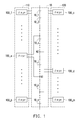
- FIG. 1 is a schematic block diagram of a circuit of a charger apparatus according to an embodiment of the disclosure.
- FIG. 3 is a schematic diagram illustrating all connection patterns that may be selected by a charger to connect a battery module series exemplarily having four battery modules.
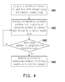
- FIG. 4 is a schematic flow chart of a charging method according to an embodiment of the disclosure.
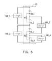
- FIG. 5 is a schematic block diagram of a circuit of a charger apparatus according to yet another embodiment of the disclosure.
- FIG. 6 is a schematic diagram illustrating experiment results of the charger apparatus shown in FIG. 5 according to an embodiment of the disclosure.
- FIG. 7 is a schematic block diagram of a circuit of a charger apparatus according to yet another embodiment of the disclosure.
- Coupled used in the full disclosure (including the claims) can refer to any direct or indirect connection means.
- first apparatus can be directly connected to the second apparatus, or the first apparatus can be indirectly connected to the second apparatus through another apparatus or a certain connection means.
- components / the elements / the steps in the drawings and the embodiments herein share the same or similar reference numerals. In different embodiments, the components / the elements / the steps having the same reference numerals or using the same wording may cross-reference to related descriptions.
- FIG. 1 is a schematic block diagram of a circuit of a charger apparatus according to an embodiment of the disclosure.
- the charger apparatus shown in FIG. 1 can charge and discharge the battery module series 10.
- the battery module series 10 includes n battery modules 10_1, 10_2, ..., 10_i, ..., 10_j, ..., 10_k, ..., and 10_n connected in series, as shown in FIG. 1 .
- i, j, k, and n are integers
- i, j, and k are smaller than n
- j ranges between i and k.
- the battery modules 10_1 to 10_n can be a single battery cell (i.e., a battery cell monomer) or a battery cell group composed of a plurality of battery cells.
- the battery modules 10_1 to 10_n can have no battery monitor circuit, or each of the battery modules 10_1 to 10_n may individually contains a dedicated battery monitor circuit. If the battery modules 10_1 to 10_n each contain a dedicated battery monitor circuit, the battery monitor circuits can be operated independently of each other.
- the charging current output terminal and the charging current input terminal of the charger are coupled separately to the positive terminal (the anode) of the first battery module 10_1 and the negative terminal (the cathode) of the last battery module 10_n. Therefore, the charging voltage of the single charger may be set to be greater than or equal to the sum of the rated voltages of the n-th battery modules 10_1 to 10_n. Hence, the single charger supplying such high voltages may be costly.
- the charger apparatus shown in FIG. 1 has a plurality of chargers. Specifically, the charger apparatus shown in FIG. 1 includes m chargers 100_1, ..., 100_a, ..., 100_b, ..., 100_c, ..., 100_d, ..., and 100_m.
- a, b, c, d and m are integers, and a, b, c, and d are all smaller than m; these chargers 100_1 to 100_m can be divided into two or more charger groups.
- the chargers 100_1 to 100_m are grouped into the first charge group 110 and the second charger group 120.
- the chargers 100_1 ⁇ 100_a ⁇ 100_b are grouped into the first charge group 110, while the chargers 100_c ⁇ 100_d ⁇ 100_m are grouped into the second charger group 120.
- the actual number of chargers in the first charger group 110 and the second charger group 120 should not be limited to that depicted in FIG. 1 . For instance, if there are four chargers, the respective number of chargers in the first charger group 110 and the second charger group 120 may be one and three or two and two.
- the charging current output terminals and the charging current input terminals of the chargers 100_1 to 100_m are coupled separately to the corresponding battery modules of the battery modules 10_1 to 10_n.
- the charging current output terminal of the charger 100_a is coupled to the positive terminal (the anode) of the i-th battery module 10_i of the battery modules 10_1 to 10_n
- the charging current input terminal of the charger 100_a is coupled to the first node N1 which is between the j-th battery module 10_j and the k-th battery module 10_k of the battery modules 10_1 to 10_n.
- the charging current output terminal of the charger 100_d is coupled to the second node N2 which is between the i-th battery module 10_i and the j-th battery module 10_j , and the charging current input terminal of the charger 100_d is coupled to the negative terminal (the cathode) of the k-th battery module 10_k.
- the quantity m of the chargers 100_1 to 100_m is greater than or equal to the quantity n of the battery modules 10_1 to 10_n.
- the charging and discharging operations on the battery modules 10_1 to 10_n by the chargers 100_1 to 100_m are independent of each other.
- the chargers 100_1 to 100_m each apply a constant current (CC) method and / or a constant voltage (CV) method to charge and discharge the corresponding battery modules of the battery modules 10_1 to 10_n, while the way to implement the chargers 100_1 to 100_m is not limited in the embodiment.
- the arrangement relationship (the charging relationship) between the chargers 100_1 to 100_m and the battery modules 10_1 to 10_n can be represented by a configuration matrix A. Therefore, the configuration matrix A is an m*n matrix, where m is the quantity of chargers 100_1 to 100_m, and n is the quantity of battery modules 10_1 to 10_n.
- the x-th column of the configuration matrix A represents the battery modules charged and discharged by the x-th charger 100_x
- the y-th row of the configuration matrix A represents the chargers that charge and discharge the y-th battery module 10_y.
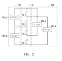
- FIG. 2 shows the arrangement relationship between the chargers 100_1 to 100_4 and the battery modules 10_1 to 10_4, and the charging voltage of the charger 100_1 can be set to be greater than or equal to the sum of the rated voltages of the two battery modules 10_1 and 10_2.
- the charging voltage of the charger 100_2 can be set to be greater than or equal to the sum of the rated voltages of the two battery modules 10_3 and 10_4.
- the charging voltage of the charger 100_3 can be set to be greater than or equal to the sum of three rated voltages of the battery modules 10_1, 10_2, and 10_3.
- the charging voltage of the charger 100_4 can be set to be greater than or equal to the sum of three rated voltages of the battery modules 10_2, 10_3, and 10_4.
- equation (2) "1" shown in the configuration matrix A in the first column and the first row represents the charging relationship between the first charger 100_1 and the first battery module 10_1; namely, the charging current of the first charger 100_1 can be directly or indirectly supplied to the first battery module 10_1.
- "0" indicates that there is no charging relationship between the first charger 100_1 and the fourth battery module 10_4.
- the other elements of the configuration matrix A can be accordingly deduced from the above.
- C 1 represents a capacitance value of the first battery module 10_1
- ⁇ V 1 represents the voltage change amount of the first battery module 10_1.
- the charging current output terminal and the charging current input terminal of each of the chargers 100_1 to 100_m is coupled separately to the corresponding battery module of the battery modules 10_1 to 10_n.
- the connection pattern of each charger coupled to the corresponding battery module series 10 includes: coupled to one battery module (n kinds of connection patterns), coupled to two battery modules (n-1 kinds of connection patterns), ..., and coupled to n battery modules (one kind of connection pattern).
- m kinds of the connection patterns may be selected from all connection patterns of the battery modules 10_1 to 10_n by the chargers 100_1 to 100_m mentioned above, wherein each of the battery modules 10_1 to 10_n can be directly or indirectly charged and discharged by at least one of the chargers.
- a PS 1 0 0 0 or 0 1 0 0 or 0 0 1 0 or 0 0 0 1 or 1 1 0 0 or 0 1 1 1 0 or 0 0 1 1 1 1 0 or 0 1 1 1 1 1 1 1 1 1 1 1 1 1 1 1 1 1 1 1 1 1 1 1 1 1 1 1 1 1 1 1 1 1 1 1 1
- FIG. 4 is a schematic flow chart of a charging method according to an embodiment of the disclosure.
- a plurality of the chargers of the charging apparatus can be at least grouped into the first charger group 110 and the second charger group 120.
- m chargers 100_1 to 100_m can be grouped into the first charger group 110 and the second charger group 120.
- each of the chargers 100_1 to 100_m respectively selects the corresponding connection pattern from a plurality of connection patterns to connect to the battery module series 10, wherein each battery module of the battery module series 10 can be charged and discharged by the chargers 100_1 to 100_m.
- the charging apparatus has four chargers 100_1 to 100_4, and the chargers can select four different kinds of the connected patterns from ten kinds of the connected patterns shown in FIG. 3 ; that is, four kinds of different matrices may be selected from ten kinds of the configurations matrices A PS shown in equation (6).
- the chargers 100_1 to 100_2 of the first charger group 110 select different corresponding connection patterns
- the chargers 100_3 to 100_4 of the second charger group 120 select different corresponding connection patterns.
- the connection patterns selected for these chargers 100_1 to 100_4 are different.
- the first charging combination indicates each of the battery modules 10_1 to 10_n is charged by some chargers of the first charger group 110
- the second charging combination indicates each of the battery modules 10_1 to 10_n is charged by some chargers of the second charger group 120.
- the configuration matrices A PS 0 0 1 1 and 1 1 1 0 are selected from the equation (6) in step S420 as the corresponding connection pattern of the chargers 100_1 and 100_2 of the first charger group 110
- the configuration matrices A PS 1 1 1 1 and 0 0 1 0 are selected in step S420 as the corresponding connection pattern of the chargers 100_3 and 100_4 of the second charger group 120.
- the first charger group 110 its corresponding first charging combination 0 1 0 1 1 1 1 1 0 indicates that the battery module 10_1 is charged/discharged by one charger, the battery module 10_2 is charged/discharged by one charger, the battery module 10_3 is charged/discharged by two chargers, and the battery charger module 10_4 is charged/discharged by one charger.
- step S420 when the connection patterns selected for the chargers 100_1 to 100_m appear to be "linearly independent of each other", the connection state can converges the battery voltage. For instance, in the battery module series 10 exemplarily having 4 battery modules 10_1 to 10_4, 1 0 0 0 , 0 1 0 0 , 0 0 1 0 , and 0 0 0 1 are selected by the chargers 100_1 to 100_4 as the connection patterns.
- step S430 If the determination result of the step S430 lies in that the connection patterns selected in step S420 do not comply with the connection rules, then the step S420 will once again be performed to select another combination of the connection patterns. If the determination result of the step S430 is that the connection patterns selected in the step S420 comply with the connection rules, then the connection relationships between the battery module series 10 and the chargers 100_1 to 100_m and the corresponding connection structures may be recognized/determined according to the connection patterns selected in the step S420 (step S440).
- the charging voltage of the charger 100_1 can be set to be greater than or equal to the sum of the rated voltages of the battery modules 10_1 and 10_2.
- the charging voltage of the charger 100_2 can be set to be greater than or equal to the sum of the rated voltages of the battery modules 10_3 and 10_4.
- the charging voltage of the charger 100_3 can be set to be greater than or equal to the sum of the rated voltages of the battery modules 10_2 and 10_3.
- the charging voltage of the charger 100_4 can be set to be greater than or equal to the sum of the rated voltage of the battery module 10_4.
- FIG. 5 shows the configuration relationship (the charging relationship) between the chargers 100_1 to 100_4 and the battery modules 10_1 to 10_4, and the configuration matrix A of the charging apparatus shown in FIG. 5 can be expressed as equation (7) as below.
- A 1 0 0 0 1 0 1 0 0 1 1 0 0 1 0 1 0 1 0 1 0 1 0 1 0 1 0 1 0 1 0 1 0 1
- the equation (7) shows that the rank of the configuration matrix A equals the quantity of the battery modules 10_1 to 10_4; that is, the configuration matrix A is a full rank matrix, so the voltage can converge during the charging/discharging operation of the charging apparatus shown in FIG. 5 . Therefore, the charging apparatus shown in FIG. 5 can simultaneously complete the charging operation and achieve battery equalization.
- additional resistors R1 and R2 are applied to simulate self-discharge of the battery modules 10_2 and 10_4.
- FIG. 6 is a schematic diagram illustrating experiment results of the charger apparatus shown in FIG. 5 according to an embodiment of the disclosure.
- the horizontal axis represents time (in units of minutes), and the ordinate axis indicates the voltage of the battery module (in units of volts).
- the charging voltage and the charging current of the chargers 100_1 to 100_3 are respectively set as 8V and 1A, while the charging voltage and the charging current of the charger 100_4 are 4V and 1A. From FIG. 6 , it can be learned that the voltages of the battery modules 10_1 to 10_4 can converge and can be equalized after the charging and discharging operations of the chargers 100_1 to 100_4, although the threshold voltages of the battery modules 10_1 to 10_4 shown in FIG. 5 are different from each other before charging, and the battery modules 10_2 and 10_4 may perform the self-discharging operation. Therefore, the charging apparatus shown in FIG. 5 can simultaneously complete the charging operation and achieve battery equalization.
- the circuit structure of the charging apparatus shown in FIG. 5 remains unchanged, but the charging voltage and the charging current of the charger 100_1 is set as 7.7V and 1A, the charging voltage and the charging current of the charger 100_2 is 8.1V and 1A, the charging voltage and the charging current of the charger 100_3 is 7.9V and 1A, and the charging voltage and the charging current of the charger 100_4 is 4.1V and 1A.
- the threshold voltages of the battery modules 10_1 to 10_4 shown in FIG. 5 are different from each other, and the battery modules 10_2 and 10_4 may perform the self-discharging operation.
- FIG. 1 , FIG. 2 , and FIG. 5 show the charging apparatus that is coupled to the corresponding battery module of the battery module series 10 in a dispersed and interleaved manner (e.g., like a matrix), so the charging apparatus can easily and efficiently perform the charging and discharging operation on the battery module series 10.
- the charging apparatus shown in FIG. 1 , FIG. 2 , and FIG. 5 is not required to be re-designed nor is required to be serially connected to a converter.
- the serially connected battery modules may be charged and discharged by the chargers, and battery equalization may be simultaneously achieved.
- the charging apparatus and the charging method do not require additional monitor/equalization circuit according to the embodiment.
- FIG. 7 is a schematic block diagram of a circuit of a charger apparatus according to yet another embodiment of the disclosure, and the embodiment shown in FIG. 7 and the embodiments shown in FIG. 1 , FIG. 2 , and FIG. 5 can be cross-referenced to one another.
- the configuration matrix A of the charging apparatus shown in FIG. 7 can be expressed as equation (7) below.
- the rank of the configuration matrix A equals the number of the battery modules 10_1 to 10_4 shown in equation (7), which indicates that the configuration matrix A is a full rank matrix.
- the charger 100_3 shown in FIG. 7 when the charger 100_3 shown in FIG. 7 is malfunctioned or disabled, the voltages of the remaining chargers 100_1, 100_2, 100_4, and 100_5, can converge during the charging and discharging operations. Therefore, the charging operations and battery equalization of the remaining chargers 100_1, 100_2, 100_4, and 100_5 shown in FIG. 7 can be completed simultaneously.
- the chargers 100_2, 100_3, 100_4, and 100_5 are selected to charge and discharge the battery modules 10_1 to 10_4, and the charger 100_1 is disabled.
- the configuration matrix A of the charging apparatus shown in FIG. 7 can be expressed as equation (9) below.
- the equation (9) shows that the rank of the configuration matrix A equals the number of the battery modules 10_1 to 10_4, which indicates that the configuration matrix A is a full rank matrix.
- the charging apparatus shown in FIG. 7 and characterized by fault tolerance can simultaneously perform the charging operation and achieve battery equalization.
- the charging apparatus depicted in FIG. 7 is coupled to the corresponding battery modules of the battery module series 10 in a dispersed and interlaced manner (e.g., a matrix); accordingly, the charging apparatus can easily and efficiently charge and discharge the battery module series 10, and thus the charging apparatus shown in FIG. 7 and the charging method described herein do not require any additional monitor/equalization circuit.
Landscapes
- Engineering & Computer Science (AREA)
- Power Engineering (AREA)
- Transportation (AREA)
- Mechanical Engineering (AREA)
- Charge And Discharge Circuits For Batteries Or The Like (AREA)
- Secondary Cells (AREA)
Applications Claiming Priority (2)
| Application Number | Priority Date | Filing Date | Title |
|---|---|---|---|
| US201361815732P | 2013-04-25 | 2013-04-25 | |
| TW102125447A TWI502849B (zh) | 2013-04-25 | 2013-07-16 | 矩陣式充電裝置與充電方法 |
Publications (3)
| Publication Number | Publication Date |
|---|---|
| EP2797205A2 true EP2797205A2 (de) | 2014-10-29 |
| EP2797205A3 EP2797205A3 (de) | 2016-04-20 |
| EP2797205B1 EP2797205B1 (de) | 2020-03-18 |
Family
ID=49385190
Family Applications (1)
| Application Number | Title | Priority Date | Filing Date |
|---|---|---|---|
| EP13189743.1A Active EP2797205B1 (de) | 2013-04-25 | 2013-10-22 | Matrixladevorrichtung und Ladeverfahren |
Country Status (3)
| Country | Link |
|---|---|
| US (1) | US9466991B2 (de) |
| EP (1) | EP2797205B1 (de) |
| CN (1) | CN104124726B (de) |
Families Citing this family (10)
| Publication number | Priority date | Publication date | Assignee | Title |
|---|---|---|---|---|
| KR101470735B1 (ko) * | 2013-05-15 | 2014-12-08 | 주식회사 엘지씨엔에스 | 직렬 연결된 다수의 2차 전지 충방전을 위한 능동 벨런스회로와 알고리즘을 구비한 2차 전지 충방전 제어장치 및 방법 |
| TWI568122B (zh) | 2015-11-09 | 2017-01-21 | 財團法人工業技術研究院 | 電池系統與其控制方法 |
| TWI618330B (zh) | 2016-10-28 | 2018-03-11 | 財團法人工業技術研究院 | 電子裝置、電池模組與電池的充放電方法 |
| TWI649939B (zh) | 2017-07-07 | 2019-02-01 | 財團法人工業技術研究院 | 電源裝置運作方法、電源裝置及電源裝置管理系統 |
| TWI657639B (zh) | 2017-12-04 | 2019-04-21 | Industrial Technology Research Institute | 電池放電流程決定方法和系統 |
| TWI649573B (zh) | 2017-12-04 | 2019-02-01 | 財團法人工業技術研究院 | 電池內短路阻抗之偵測方法和系統 |
| TWI666848B (zh) * | 2018-09-12 | 2019-07-21 | 財團法人工業技術研究院 | 蓄電系統消防裝置及其運作方法 |
| KR102747640B1 (ko) * | 2018-11-07 | 2024-12-31 | 삼성전자주식회사 | 배터리 장치를 충전하는 충전 집적 회로 및 이를 포함하는 전자 장치 |
| US11349317B2 (en) * | 2018-11-07 | 2022-05-31 | Samsung Electronics Co., Ltd. | Charger integrated circuit for charging battery device and electronic device including the charger integrated circuit |
| CN116581852B (zh) * | 2023-07-12 | 2023-09-22 | 钰泰半导体股份有限公司 | 基于降压充电电路的多串锂电池组充电电路、方法 |
Family Cites Families (24)
| Publication number | Priority date | Publication date | Assignee | Title |
|---|---|---|---|---|
| US5821733A (en) | 1994-02-22 | 1998-10-13 | Packard Bell Nec | Multiple cell and serially connected rechargeable batteries and charging system |
| JPH0833219A (ja) | 1994-07-18 | 1996-02-02 | Integuran Kk | 直列電池の充電装置 |
| TW421608B (en) * | 1996-11-12 | 2001-02-11 | Mitsubishi Gas Chemical Co | Method for drying resin-used electronic parts |
| US6377024B1 (en) | 2001-03-23 | 2002-04-23 | The Boeing Company | Method and system for charge equalization of lithium-ion batteries |
| US6943529B2 (en) | 2001-12-16 | 2005-09-13 | Zinc Matrix Power, Inc. | Battery charging system |
| JP3867581B2 (ja) * | 2002-01-17 | 2007-01-10 | 松下電器産業株式会社 | 組電池システム |
| US6771045B1 (en) | 2002-09-05 | 2004-08-03 | Ise Corporation | Systems and methods for battery charging and equalization |
| US20050269988A1 (en) | 2004-06-04 | 2005-12-08 | Maxwell Technologies, Inc. | Voltage balancing circuit for multi-cell modules |
| TWM289925U (en) | 2005-11-09 | 2006-04-21 | Sino American Electronic Co Lt | Smart-type battery charger with equalizer circuit |
| JP5285322B2 (ja) * | 2008-04-16 | 2013-09-11 | パナソニック株式会社 | 電圧均等化装置並びに充電装置、組蓄電装置、充電システム |
| KR101077154B1 (ko) * | 2008-04-22 | 2011-10-27 | 한국과학기술원 | 직렬연결 배터리 스트링을 위한 2단 전하 균일 방법 및장치 |
| JP5015073B2 (ja) | 2008-06-20 | 2012-08-29 | 株式会社竹内製作所 | 充電システム |
| KR101093597B1 (ko) * | 2009-01-30 | 2011-12-15 | 한국과학기술원 | 정전압원을 이용한 자동전하균일 장치 |
| US8541980B2 (en) * | 2009-05-22 | 2013-09-24 | Intersil Americas LLC | System and method for cell balancing and charging |
| US8148942B2 (en) | 2009-11-05 | 2012-04-03 | O2Micro International Limited | Charging systems with cell balancing functions |
| CN102823104B (zh) | 2010-02-05 | 2016-05-11 | 法国原子能源和替代能源委员会 | 用于电池的充电均衡系统 |
| JP4848038B2 (ja) | 2010-02-26 | 2011-12-28 | 幸男 高橋 | 充電器及び充電装置 |
| US8564246B2 (en) | 2010-03-30 | 2013-10-22 | Grrreen, Inc. | Battery charging system and method |
| US8598840B2 (en) | 2010-04-15 | 2013-12-03 | Launchpoint Energy And Power Llc | Fault-tolerant battery management system, circuits and methods |
| EP2666228B1 (de) | 2011-01-22 | 2022-08-31 | Alpha Technologies Services, Inc. | Ladungsausgleichssystem und -verfahren |
| TWM421608U (en) * | 2011-09-21 | 2012-01-21 | Green Solution Tech Co Ltd | Battery balancing controller, battery apparatus and battery module case for applying the same |
| CN102522602A (zh) | 2011-12-02 | 2012-06-27 | 苏州冠硕新能源有限公司 | 一种对相互串联的若干电池单元进行主动平衡的方法 |
| CN202872396U (zh) * | 2012-08-29 | 2013-04-10 | 华南理工大学 | 一种基于电感储能的串联电池组充放电均衡电路 |
| CN103066665A (zh) * | 2013-01-18 | 2013-04-24 | 同济大学 | 一种动力锂离子电池模块的主动均衡电路及其均衡方法 |
-
2013
- 2013-09-02 CN CN201310392236.XA patent/CN104124726B/zh active Active
- 2013-10-09 US US14/049,236 patent/US9466991B2/en active Active
- 2013-10-22 EP EP13189743.1A patent/EP2797205B1/de active Active
Non-Patent Citations (1)
| Title |
|---|
| None |
Also Published As
| Publication number | Publication date |
|---|---|
| EP2797205A3 (de) | 2016-04-20 |
| US9466991B2 (en) | 2016-10-11 |
| CN104124726A (zh) | 2014-10-29 |
| EP2797205B1 (de) | 2020-03-18 |
| US20140320067A1 (en) | 2014-10-30 |
| CN104124726B (zh) | 2016-08-31 |
Similar Documents
| Publication | Publication Date | Title |
|---|---|---|
| US9466991B2 (en) | Matrix charger apparatus and charging method | |
| KR102120797B1 (ko) | 배터리 충방전 장치 및 방법 | |
| Baronti et al. | Investigation of series-parallel connections of multi-module batteries for electrified vehicles | |
| Brandl et al. | Batteries and battery management systems for electric vehicles | |
| Wang et al. | A LiFePO4 battery pack capacity estimation approach considering in-parallel cell safety in electric vehicles | |
| DE102017003719A1 (de) | Vorrichtung und Verfahren zur Aufladung des Mehrzellenakkumulators mit direktem Ladungsausgleich | |
| Lv et al. | Performance of LiFePO4 batteries in parallel based on connection topology | |
| KR101614046B1 (ko) | 배터리 시스템 관리 장치 | |
| JP2011188700A (ja) | 電源システム、放電制御方法および放電制御プログラム | |
| Kim et al. | Screening process of Li-Ion series battery pack for improved voltage/SOC balancing | |
| Qahouq et al. | DC-DC power converter controller for SOC balancing of paralleled battery system | |
| Grün et al. | Passive Hybrid Storage Systems: Influence of circuit and system design on performance and lifetime | |
| CN114938049A (zh) | 一种电池组的充放电平衡保护检测管理的方法及系统 | |
| Vattem et al. | Design and simulation of passive cell balancing schematic for battery module with eight cells | |
| DE102011054460A1 (de) | Automatisches Zellbalancer-Reparaturwerkzeug für ein Batterieteil/Modul | |
| CN116545067B (zh) | 一种电池组的均衡电路及储能系统 | |
| TWI502849B (zh) | 矩陣式充電裝置與充電方法 | |
| Ditsworth et al. | A battery pack reconfiguration scheme for improved charge balancing | |
| Di Rienzo et al. | Comparison of active energy-balance architectures for second-life battery dynamic equalization | |
| Mubenga | The efficiency measuring apparatus for the design of li-ion batteries equalizers | |
| KR20160077689A (ko) | Bms 시뮬레이션 장치 | |
| DE102012212648A1 (de) | Batteriesystem mit Zellüberwachungsschaltungen sowie ein Verfahren zum Balancing der Ladezustände von Batteriezellen eines Batteriesystems | |
| Vishnu et al. | Smart Cell Equalizer for Lithium-ion Battery Packs | |
| Cao et al. | Controller evaluation of wirelessly distributed and enabled battery energy storage system under unequal battery modules capacity values | |
| US20240106254A1 (en) | Power Storage System |
Legal Events
| Date | Code | Title | Description |
|---|---|---|---|
| PUAI | Public reference made under article 153(3) epc to a published international application that has entered the european phase |
Free format text: ORIGINAL CODE: 0009012 |
|
| 17P | Request for examination filed |
Effective date: 20131022 |
|
| AK | Designated contracting states |
Kind code of ref document: A2 Designated state(s): AL AT BE BG CH CY CZ DE DK EE ES FI FR GB GR HR HU IE IS IT LI LT LU LV MC MK MT NL NO PL PT RO RS SE SI SK SM TR |
|
| AX | Request for extension of the european patent |
Extension state: BA ME |
|
| PUAL | Search report despatched |
Free format text: ORIGINAL CODE: 0009013 |
|
| AK | Designated contracting states |
Kind code of ref document: A3 Designated state(s): AL AT BE BG CH CY CZ DE DK EE ES FI FR GB GR HR HU IE IS IT LI LT LU LV MC MK MT NL NO PL PT RO RS SE SI SK SM TR |
|
| AX | Request for extension of the european patent |
Extension state: BA ME |
|
| RIC1 | Information provided on ipc code assigned before grant |
Ipc: H02J 7/14 20060101AFI20160316BHEP Ipc: B60L 11/18 20060101ALI20160316BHEP Ipc: H02J 7/00 20060101ALI20160316BHEP |
|
| R17P | Request for examination filed (corrected) |
Effective date: 20160721 |
|
| RBV | Designated contracting states (corrected) |
Designated state(s): AL AT BE BG CH CY CZ DE DK EE ES FI FR GB GR HR HU IE IS IT LI LT LU LV MC MK MT NL NO PL PT RO RS SE SI SK SM TR |
|
| RAP1 | Party data changed (applicant data changed or rights of an application transferred) |
Owner name: KWANG YANG MOTOR CO., LTD. |
|
| RIC1 | Information provided on ipc code assigned before grant |
Ipc: B60L 53/22 20190101ALI20190910BHEP Ipc: H02J 7/00 20060101ALI20190910BHEP Ipc: H02J 7/14 20060101AFI20190910BHEP |
|
| GRAP | Despatch of communication of intention to grant a patent |
Free format text: ORIGINAL CODE: EPIDOSNIGR1 |
|
| STAA | Information on the status of an ep patent application or granted ep patent |
Free format text: STATUS: GRANT OF PATENT IS INTENDED |
|
| INTG | Intention to grant announced |
Effective date: 20191104 |
|
| GRAS | Grant fee paid |
Free format text: ORIGINAL CODE: EPIDOSNIGR3 |
|
| GRAA | (expected) grant |
Free format text: ORIGINAL CODE: 0009210 |
|
| STAA | Information on the status of an ep patent application or granted ep patent |
Free format text: STATUS: THE PATENT HAS BEEN GRANTED |
|
| AK | Designated contracting states |
Kind code of ref document: B1 Designated state(s): AL AT BE BG CH CY CZ DE DK EE ES FI FR GB GR HR HU IE IS IT LI LT LU LV MC MK MT NL NO PL PT RO RS SE SI SK SM TR |
|
| REG | Reference to a national code |
Ref country code: GB Ref legal event code: FG4D |
|
| REG | Reference to a national code |
Ref country code: DE Ref legal event code: R096 Ref document number: 602013066896 Country of ref document: DE |
|
| REG | Reference to a national code |
Ref country code: AT Ref legal event code: REF Ref document number: 1247053 Country of ref document: AT Kind code of ref document: T Effective date: 20200415 Ref country code: IE Ref legal event code: FG4D |
|
| REG | Reference to a national code |
Ref country code: NL Ref legal event code: FP |
|
| PG25 | Lapsed in a contracting state [announced via postgrant information from national office to epo] |
Ref country code: RS Free format text: LAPSE BECAUSE OF FAILURE TO SUBMIT A TRANSLATION OF THE DESCRIPTION OR TO PAY THE FEE WITHIN THE PRESCRIBED TIME-LIMIT Effective date: 20200318 Ref country code: FI Free format text: LAPSE BECAUSE OF FAILURE TO SUBMIT A TRANSLATION OF THE DESCRIPTION OR TO PAY THE FEE WITHIN THE PRESCRIBED TIME-LIMIT Effective date: 20200318 Ref country code: NO Free format text: LAPSE BECAUSE OF FAILURE TO SUBMIT A TRANSLATION OF THE DESCRIPTION OR TO PAY THE FEE WITHIN THE PRESCRIBED TIME-LIMIT Effective date: 20200618 |
|
| PG25 | Lapsed in a contracting state [announced via postgrant information from national office to epo] |
Ref country code: GR Free format text: LAPSE BECAUSE OF FAILURE TO SUBMIT A TRANSLATION OF THE DESCRIPTION OR TO PAY THE FEE WITHIN THE PRESCRIBED TIME-LIMIT Effective date: 20200619 Ref country code: BG Free format text: LAPSE BECAUSE OF FAILURE TO SUBMIT A TRANSLATION OF THE DESCRIPTION OR TO PAY THE FEE WITHIN THE PRESCRIBED TIME-LIMIT Effective date: 20200618 Ref country code: SE Free format text: LAPSE BECAUSE OF FAILURE TO SUBMIT A TRANSLATION OF THE DESCRIPTION OR TO PAY THE FEE WITHIN THE PRESCRIBED TIME-LIMIT Effective date: 20200318 Ref country code: LV Free format text: LAPSE BECAUSE OF FAILURE TO SUBMIT A TRANSLATION OF THE DESCRIPTION OR TO PAY THE FEE WITHIN THE PRESCRIBED TIME-LIMIT Effective date: 20200318 Ref country code: HR Free format text: LAPSE BECAUSE OF FAILURE TO SUBMIT A TRANSLATION OF THE DESCRIPTION OR TO PAY THE FEE WITHIN THE PRESCRIBED TIME-LIMIT Effective date: 20200318 |
|
| REG | Reference to a national code |
Ref country code: LT Ref legal event code: MG4D |
|
| REG | Reference to a national code |
Ref country code: ES Ref legal event code: FG2A Ref document number: 2786057 Country of ref document: ES Kind code of ref document: T3 Effective date: 20201008 |
|
| PG25 | Lapsed in a contracting state [announced via postgrant information from national office to epo] |
Ref country code: SM Free format text: LAPSE BECAUSE OF FAILURE TO SUBMIT A TRANSLATION OF THE DESCRIPTION OR TO PAY THE FEE WITHIN THE PRESCRIBED TIME-LIMIT Effective date: 20200318 Ref country code: EE Free format text: LAPSE BECAUSE OF FAILURE TO SUBMIT A TRANSLATION OF THE DESCRIPTION OR TO PAY THE FEE WITHIN THE PRESCRIBED TIME-LIMIT Effective date: 20200318 Ref country code: PT Free format text: LAPSE BECAUSE OF FAILURE TO SUBMIT A TRANSLATION OF THE DESCRIPTION OR TO PAY THE FEE WITHIN THE PRESCRIBED TIME-LIMIT Effective date: 20200812 Ref country code: SK Free format text: LAPSE BECAUSE OF FAILURE TO SUBMIT A TRANSLATION OF THE DESCRIPTION OR TO PAY THE FEE WITHIN THE PRESCRIBED TIME-LIMIT Effective date: 20200318 Ref country code: IS Free format text: LAPSE BECAUSE OF FAILURE TO SUBMIT A TRANSLATION OF THE DESCRIPTION OR TO PAY THE FEE WITHIN THE PRESCRIBED TIME-LIMIT Effective date: 20200718 Ref country code: RO Free format text: LAPSE BECAUSE OF FAILURE TO SUBMIT A TRANSLATION OF THE DESCRIPTION OR TO PAY THE FEE WITHIN THE PRESCRIBED TIME-LIMIT Effective date: 20200318 Ref country code: CZ Free format text: LAPSE BECAUSE OF FAILURE TO SUBMIT A TRANSLATION OF THE DESCRIPTION OR TO PAY THE FEE WITHIN THE PRESCRIBED TIME-LIMIT Effective date: 20200318 Ref country code: LT Free format text: LAPSE BECAUSE OF FAILURE TO SUBMIT A TRANSLATION OF THE DESCRIPTION OR TO PAY THE FEE WITHIN THE PRESCRIBED TIME-LIMIT Effective date: 20200318 |
|
| PGFP | Annual fee paid to national office [announced via postgrant information from national office to epo] |
Ref country code: NL Payment date: 20200928 Year of fee payment: 8 |
|
| REG | Reference to a national code |
Ref country code: AT Ref legal event code: MK05 Ref document number: 1247053 Country of ref document: AT Kind code of ref document: T Effective date: 20200318 |
|
| REG | Reference to a national code |
Ref country code: DE Ref legal event code: R097 Ref document number: 602013066896 Country of ref document: DE |
|
| PLBE | No opposition filed within time limit |
Free format text: ORIGINAL CODE: 0009261 |
|
| STAA | Information on the status of an ep patent application or granted ep patent |
Free format text: STATUS: NO OPPOSITION FILED WITHIN TIME LIMIT |
|
| PG25 | Lapsed in a contracting state [announced via postgrant information from national office to epo] |
Ref country code: AT Free format text: LAPSE BECAUSE OF FAILURE TO SUBMIT A TRANSLATION OF THE DESCRIPTION OR TO PAY THE FEE WITHIN THE PRESCRIBED TIME-LIMIT Effective date: 20200318 Ref country code: DK Free format text: LAPSE BECAUSE OF FAILURE TO SUBMIT A TRANSLATION OF THE DESCRIPTION OR TO PAY THE FEE WITHIN THE PRESCRIBED TIME-LIMIT Effective date: 20200318 |
|
| PGFP | Annual fee paid to national office [announced via postgrant information from national office to epo] |
Ref country code: DE Payment date: 20201027 Year of fee payment: 8 Ref country code: ES Payment date: 20201110 Year of fee payment: 8 Ref country code: FR Payment date: 20201027 Year of fee payment: 8 |
|
| 26N | No opposition filed |
Effective date: 20201221 |
|
| PG25 | Lapsed in a contracting state [announced via postgrant information from national office to epo] |
Ref country code: PL Free format text: LAPSE BECAUSE OF FAILURE TO SUBMIT A TRANSLATION OF THE DESCRIPTION OR TO PAY THE FEE WITHIN THE PRESCRIBED TIME-LIMIT Effective date: 20200318 |
|
| PG25 | Lapsed in a contracting state [announced via postgrant information from national office to epo] |
Ref country code: SI Free format text: LAPSE BECAUSE OF FAILURE TO SUBMIT A TRANSLATION OF THE DESCRIPTION OR TO PAY THE FEE WITHIN THE PRESCRIBED TIME-LIMIT Effective date: 20200318 |
|
| REG | Reference to a national code |
Ref country code: CH Ref legal event code: PL |
|
| GBPC | Gb: european patent ceased through non-payment of renewal fee |
Effective date: 20201022 |
|
| PG25 | Lapsed in a contracting state [announced via postgrant information from national office to epo] |
Ref country code: MC Free format text: LAPSE BECAUSE OF FAILURE TO SUBMIT A TRANSLATION OF THE DESCRIPTION OR TO PAY THE FEE WITHIN THE PRESCRIBED TIME-LIMIT Effective date: 20200318 Ref country code: LU Free format text: LAPSE BECAUSE OF NON-PAYMENT OF DUE FEES Effective date: 20201022 |
|
| REG | Reference to a national code |
Ref country code: BE Ref legal event code: MM Effective date: 20201031 |
|
| PG25 | Lapsed in a contracting state [announced via postgrant information from national office to epo] |
Ref country code: LI Free format text: LAPSE BECAUSE OF NON-PAYMENT OF DUE FEES Effective date: 20201031 Ref country code: GB Free format text: LAPSE BECAUSE OF NON-PAYMENT OF DUE FEES Effective date: 20201022 Ref country code: CH Free format text: LAPSE BECAUSE OF NON-PAYMENT OF DUE FEES Effective date: 20201031 Ref country code: BE Free format text: LAPSE BECAUSE OF NON-PAYMENT OF DUE FEES Effective date: 20201031 |
|
| PG25 | Lapsed in a contracting state [announced via postgrant information from national office to epo] |
Ref country code: IE Free format text: LAPSE BECAUSE OF NON-PAYMENT OF DUE FEES Effective date: 20201022 |
|
| REG | Reference to a national code |
Ref country code: DE Ref legal event code: R119 Ref document number: 602013066896 Country of ref document: DE |
|
| PG25 | Lapsed in a contracting state [announced via postgrant information from national office to epo] |
Ref country code: TR Free format text: LAPSE BECAUSE OF FAILURE TO SUBMIT A TRANSLATION OF THE DESCRIPTION OR TO PAY THE FEE WITHIN THE PRESCRIBED TIME-LIMIT Effective date: 20200318 Ref country code: MT Free format text: LAPSE BECAUSE OF FAILURE TO SUBMIT A TRANSLATION OF THE DESCRIPTION OR TO PAY THE FEE WITHIN THE PRESCRIBED TIME-LIMIT Effective date: 20200318 Ref country code: CY Free format text: LAPSE BECAUSE OF FAILURE TO SUBMIT A TRANSLATION OF THE DESCRIPTION OR TO PAY THE FEE WITHIN THE PRESCRIBED TIME-LIMIT Effective date: 20200318 |
|
| REG | Reference to a national code |
Ref country code: NL Ref legal event code: MM Effective date: 20211101 |
|
| PG25 | Lapsed in a contracting state [announced via postgrant information from national office to epo] |
Ref country code: MK Free format text: LAPSE BECAUSE OF FAILURE TO SUBMIT A TRANSLATION OF THE DESCRIPTION OR TO PAY THE FEE WITHIN THE PRESCRIBED TIME-LIMIT Effective date: 20200318 Ref country code: AL Free format text: LAPSE BECAUSE OF FAILURE TO SUBMIT A TRANSLATION OF THE DESCRIPTION OR TO PAY THE FEE WITHIN THE PRESCRIBED TIME-LIMIT Effective date: 20200318 |
|
| PG25 | Lapsed in a contracting state [announced via postgrant information from national office to epo] |
Ref country code: NL Free format text: LAPSE BECAUSE OF NON-PAYMENT OF DUE FEES Effective date: 20211101 Ref country code: DE Free format text: LAPSE BECAUSE OF NON-PAYMENT OF DUE FEES Effective date: 20220503 |
|
| PG25 | Lapsed in a contracting state [announced via postgrant information from national office to epo] |
Ref country code: FR Free format text: LAPSE BECAUSE OF NON-PAYMENT OF DUE FEES Effective date: 20211031 |
|
| REG | Reference to a national code |
Ref country code: ES Ref legal event code: FD2A Effective date: 20230216 |
|
| PG25 | Lapsed in a contracting state [announced via postgrant information from national office to epo] |
Ref country code: ES Free format text: LAPSE BECAUSE OF NON-PAYMENT OF DUE FEES Effective date: 20211023 |
|
| PGFP | Annual fee paid to national office [announced via postgrant information from national office to epo] |
Ref country code: IT Payment date: 20251028 Year of fee payment: 13 |