EP2797308A2 - Système et procédé de panoramique en direct - Google Patents
Système et procédé de panoramique en direct Download PDFInfo
- Publication number
- EP2797308A2 EP2797308A2 EP20140165162 EP14165162A EP2797308A2 EP 2797308 A2 EP2797308 A2 EP 2797308A2 EP 20140165162 EP20140165162 EP 20140165162 EP 14165162 A EP14165162 A EP 14165162A EP 2797308 A2 EP2797308 A2 EP 2797308A2
- Authority
- EP
- European Patent Office
- Prior art keywords
- live
- interest
- image
- cropping window
- image sensor
- Prior art date
- Legal status (The legal status is an assumption and is not a legal conclusion. Google has not performed a legal analysis and makes no representation as to the accuracy of the status listed.)
- Withdrawn
Links
Images






Classifications
-
- H—ELECTRICITY
- H04—ELECTRIC COMMUNICATION TECHNIQUE
- H04N—PICTORIAL COMMUNICATION, e.g. TELEVISION
- H04N7/00—Television systems
- H04N7/18—Closed-circuit television [CCTV] systems, i.e. systems in which the video signal is not broadcast
- H04N7/183—Closed-circuit television [CCTV] systems, i.e. systems in which the video signal is not broadcast for receiving images from a single remote source
-
- G—PHYSICS
- G09—EDUCATION; CRYPTOGRAPHY; DISPLAY; ADVERTISING; SEALS
- G09B—EDUCATIONAL OR DEMONSTRATION APPLIANCES; APPLIANCES FOR TEACHING, OR COMMUNICATING WITH, THE BLIND, DEAF OR MUTE; MODELS; PLANETARIA; GLOBES; MAPS; DIAGRAMS
- G09B21/00—Teaching, or communicating with, the blind, deaf or mute
- G09B21/001—Teaching or communicating with blind persons
- G09B21/008—Teaching or communicating with blind persons using visual presentation of the information for the partially sighted
-
- G—PHYSICS
- G06—COMPUTING OR CALCULATING; COUNTING
- G06T—IMAGE DATA PROCESSING OR GENERATION, IN GENERAL
- G06T3/00—Geometric image transformations in the plane of the image
- G06T3/02—Affine transformations
-
- H—ELECTRICITY
- H04—ELECTRIC COMMUNICATION TECHNIQUE
- H04N—PICTORIAL COMMUNICATION, e.g. TELEVISION
- H04N1/00—Scanning, transmission or reproduction of documents or the like, e.g. facsimile transmission; Details thereof
- H04N1/387—Composing, repositioning or otherwise geometrically modifying originals
- H04N1/3872—Repositioning or masking
- H04N1/3873—Repositioning or masking defined only by a limited number of coordinate points or parameters, e.g. corners, centre; for trimming
-
- H—ELECTRICITY
- H04—ELECTRIC COMMUNICATION TECHNIQUE
- H04N—PICTORIAL COMMUNICATION, e.g. TELEVISION
- H04N23/00—Cameras or camera modules comprising electronic image sensors; Control thereof
- H04N23/58—Means for changing the camera field of view without moving the camera body, e.g. nutating or panning of optics or image sensors
-
- H—ELECTRICITY
- H04—ELECTRIC COMMUNICATION TECHNIQUE
- H04N—PICTORIAL COMMUNICATION, e.g. TELEVISION
- H04N23/00—Cameras or camera modules comprising electronic image sensors; Control thereof
- H04N23/60—Control of cameras or camera modules
- H04N23/69—Control of means for changing angle of the field of view, e.g. optical zoom objectives or electronic zooming
-
- H—ELECTRICITY
- H04—ELECTRIC COMMUNICATION TECHNIQUE
- H04N—PICTORIAL COMMUNICATION, e.g. TELEVISION
- H04N25/00—Circuitry of solid-state image sensors [SSIS]; Control thereof
- H04N25/40—Extracting pixel data from image sensors by controlling scanning circuits, e.g. by modifying the number of pixels sampled or to be sampled
- H04N25/44—Extracting pixel data from image sensors by controlling scanning circuits, e.g. by modifying the number of pixels sampled or to be sampled by partially reading an SSIS array
- H04N25/443—Extracting pixel data from image sensors by controlling scanning circuits, e.g. by modifying the number of pixels sampled or to be sampled by partially reading an SSIS array by reading pixels from selected two-dimensional [2D] regions of the array, e.g. for windowing or digital zooming
-
- H—ELECTRICITY
- H04—ELECTRIC COMMUNICATION TECHNIQUE
- H04N—PICTORIAL COMMUNICATION, e.g. TELEVISION
- H04N25/00—Circuitry of solid-state image sensors [SSIS]; Control thereof
- H04N25/40—Extracting pixel data from image sensors by controlling scanning circuits, e.g. by modifying the number of pixels sampled or to be sampled
- H04N25/46—Extracting pixel data from image sensors by controlling scanning circuits, e.g. by modifying the number of pixels sampled or to be sampled by combining or binning pixels
Definitions
- the present invention generally relates to the field of imaging systems and methods, and more particularly concerns a system and a method for acquiring an image of an entire working area and providing therefrom a pannable live representation of a portion of the working area, suitable for use by low-vision individuals.
- Loss of visual acuity is a growing concern worldwide.
- the World Health Organization currently estimates to 2.5% the incidence of low vision in industrialized countries and this figure is expected to continue to increase with ageing population.
- Low vision may be generally referred to as a condition where ordinary eye glasses, lens implants or contact lenses are not sufficient for providing sharp sight.
- the largest growing segment of the low-vision population in developed countries is expected to be people aged 65 years old and older. This is mainly due to age-related eye diseases such as macular degeneration, glaucoma and diabetic retinopathy, cataract, detached retina, and retinitis pigmentosa. Some people are also born with low vision.
- desktop video magnifiers generally include a video monitor mounted on a frame structure having a gooseneck shape.
- a camera provided with optical zooming capabilities is mounted on the frame structure and disposed so that the field of view of the camera intersects a working area on which a user can dispose an object of interest to be magnified.
- the object may be a document including text content that the user wishes to read.
- the camera feeds a video processor with a video stream of a portion of the working area, and the video processor in turn feeds this video stream with an increased sharpness and enhanced contrast to the video monitor.
- the camera In conventional video magnifiers, the camera typically has a relatively narrow field of view and, therefore, can only acquire a video stream of a limited portion of the working area. In such cases, the user must displace the document with respect to the field of view of the camera in order to access different portions of the document.
- the working area on which the document is placed is typically an XY translation table assembled on rails. Such a configuration allows the user to freely move the XY table and the document thereon to bring different portions of the document within the field of view of the camera. In other words, in conventional video magnifiers, panning across the image or video stream of the document may be achieved by moving the XY table and the document thereon with respect to the field of view of the camera.
- Moving the XY table is often considered a difficult task by users, because they must translate the table in a direction which is often considered counterintuitive. For example, to view the region at the left of the currently displayed image, the XY table must be moved to the right. Hence, panning in conventional video magnifiers is not considered optimal for certain applications, thereby negatively impacting the efficiency, functionality and ease-of-use of these devices.
- a live panning system for providing a live representation of a portion of a working area.
- the live panning system includes
- a live panning method for providing a live representation of a portion of a working area. The method includes the steps of:
- the present description generally relates to a live panning system and method for providing a live representation of a portion of a working area.
- a live panning system for providing a live representation of a portion of a working area.
- the live panning system 20 includes an image sensor 22 configured to acquire an image 24 (see, e.g., FIG. 5A ) of the entire working area 26 and a processing unit 28 monitoring viewing instructions from a user selecting a region of interest 36 within the image 24 that corresponds to a portion 38 of the working area 26.
- the portion 38 of the working area 26 corresponds to the entire working area 26.
- FIGs. 8A to 8C and 11A to 11D illustrate cases where the portion 38 of the working area 26 is less than the entire working area 26.
- the live panning system 20 may optionally include a display unit 40 displaying, in real-time and at a display frame rate, a live representation 42 of the region of interest 36 corresponding to the portion 38 of the working area 26.
- the live panning system may also include an input interface 44 in communication with the processing unit 28 to allow the user to act on the live representation 42 of the portion 38 of the working area 26.
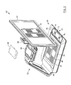
- the live panning system may be particularly useful in video magnifiers directed to individuals suffering from low vision or other visual impairments, such as the one illustrated in FIG. 1 .
- Conventional video magnifiers for low-vision individuals generally involve displacing the working area to bring different portions of the working area within the field of view of the image sensor. For at least this reason, panning in conventional video magnifiers may be cumbersome or inefficient, leading to degradation in performance and usability.
- embodiments of the live panning system can achieve panning without the user having to physically or mechanically move the image sensor and the working area relative to each other.
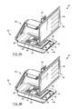
- FIGs. 8A to 8C illustrate the effect of panning the region of interest 36 within the image 24 at a given magnification level to bring into view different portions 38 of the working area 26 on the display unit 40, in response to panning commands depicted schematically in FIGs. 5A to 5D .
- magnification level is understood to refer to the ratio of the live representation of the portion of working area displayed by the live panning system to the actual size of the portion of the working area. It will be understood that the portion 38 of the working area 26 may correspond to the entire the working area 26 (see, e.g., FIG. 1 ) or to a partial region thereof (see, e.g., FIGs. 8A to 8C ).
- the live panning system corresponds to a digital panning of the image acquired by the image sensor.
- digital panning involves a user moving, in real-time, the region of interest corresponding to the portion of the working area within the image of the entire working area, without having to physically displace the field of view of the image sensor with respect to the working area.
- live and real-time are used herein as practical terms depending upon the requirements or particularities of an intended application of the live panning system. These terms generally refer to the fact that the live panning system allows panning operations to be performed on the image relatively seamlessly on the typical scale of human perception. As a result, the live representation of the portion of the working area corresponding to the region of interest of the image is provided to the user with negligible, insignificant or acceptable time lag or delay.
- working area is meant to refer to any physical structure, surface or region encompassed within the field of view of the image sensor and of which a portion is to be provided as the live representation by the live panning system.
- the working area 26 is a generally flat surface on which can be placed an object 48, for example a printed document that a user wishes to read.
- Typical objects may include, without being limited to, printed and handwritten documents, books, magazines, newspapers, letters, bills and checks, but also any three-dimensional object of interest.
- embodiments of the invention may be targeted or well adapted to low-vision individuals, one of ordinary skill in the art will understand that embodiments of the invention can, in general, be used by any person desiring a device capable of panning across an image of a working area in real-time and without having to move the working area with respect to the field of view of the image sensor, and vice versa.
- the live panning system 20 includes a base station 50 provided with a frame structure 52 having a gooseneck shape and on which is mounted the display unit 40.
- a camera unit 54 incorporating the image sensor 22 is mounted on the frame structure 52 and disposed such that the field of view 46 of the image sensor 22 circumscribes or encompasses the entire working area 26 on which a user can dispose an object 48 whose live representation 42 is to be displayed on the display unit 40.
- the live panning system 20 is intended to be used a stand-alone device such that the image sensor 22 and the processing unit 28 are integrally provided within the frame structure 52.
- the frame structure 52 includes a bottom platform 56 adapted to be disposed on a flat surface such as a table, desk, counter, or the like.
- the bottom platform 56 is shown as having a rectangular shape, but one of ordinary skill in the art will understand that other shapes could be considered in other embodiments.
- a region of the bottom platform 56 on which an object 48 (e.g., a document) can be disposed can define the working area 26.
- the working area 26 can be said to coincide, at least partly, with the intersection plane between the bottom platform 56 and the field of view 46 of the image sensor 22 of the live panning system 20.
- the entire bottom platform 56 may define the working area 26.
- the frame structure 52 need not include a bottom platform 56, such that the object 48 to be viewed can rest on a flat surface on which the base station 50 is supported or on another flat surface. In such a case, the working area 26 coincides at least partly with this flat surface.
- the live panning system 20 including the image sensor 22 and the processing unit 28 may be provided in a handheld device 58.
- a handheld device 58 An example of such a handheld device is described in patent application no. 13/724,964 entitled "Handheld magnification device with a two-camera module".
- the handheld device 58 may be used as a standalone portable device.
- the handheld device 58 may alternatively or additionally be connectable for use in combination with stationary equipment.
- the handheld device 58 incorporating the live panning system 20 according to embodiments of the invention could be removably docked to the frame structure 52 of a base station 50.
- An example of such a modular magnification system is described in patent application no. 13/724,896 entitled "Magnification system”.
- the live panning system 20 includes an image sensor 22 configured to acquire an image of the entire working area 26.
- An example of such an image 24 of the entire working area 26 is shown in FIG. 5A .
- the image sensor 22 is part of the camera unit 54 mounted on the frame structure 52 of the base station 50.
- the camera unit 54 is disposed over the working area 26 such that the field of view 46 of the image sensor 22 encompasses the entire working area 26.
- the working area 26 encompassed by the field of view 46 of the image sensor 22 is sufficiently large to allow the image 24 of the entire surface of a document having a standard letter size to be acquired at a distance of less than about 25 cm.
- standard paper sizes include, without being limited to, Letter (215.9 mm ⁇ 279.4 mm), A3 (297 mm ⁇ 420 mm), A4 (210 mm ⁇ 297 mm), A5 (148 mm ⁇ 210 mm), and the like.
- Letter (215.9 mm ⁇ 279.4 mm) A3 (297 mm ⁇ 420 mm), A4 (210 mm ⁇ 297 mm), A5 (148 mm ⁇ 210 mm), and the like.
- the term “camera unit” refers herein to any component or combination of components capable of acquiring an image of a scene. More particularly, the term “camera unit” is meant to encompass the imaging elements, including imaging optics and the image sensor, as well as the camera circuitry associated therewith, which are collectively used to acquire the image of the entire working area. In some embodiments, the camera unit is preferably a high-resolution digital camera, for example 1 megapixel or higher, although lower resolution cameras or non-digital devices may be used without departing from the scope of the present invention.
- image sensor generally refers herein to any photosensitive device able to detect optical radiation emitted by, reflected by or otherwise emanating from an object or scene, and to generate an image of the object or scene based on the detected optical radiation.
- the image sensor 22 can be embodied by complementary metal-oxide-semiconductor (CMOS) or charge-coupled device (CCD) pixel sensors, but other types of image sensors (e.g., charge injection devices or photo diode arrays) could be used without departing from the scope of the present invention.
- CMOS complementary metal-oxide-semiconductor
- CCD charge-coupled device
- the image sensor 22 has a field of view 46 directed and extending toward the working area 26.
- the term "field of view” generally refers to the solid angular extent of a given scene whose image is to be acquired by the image sensor.
- the field of view 46 is rectangular but other shapes are possible in other embodiments.
- the image sensor 22 includes an array 30 of pixels, wherein each pixel provides pixel data of the image 24.
- the pixel array 30 defines the optically active area of the image sensor 22, such that upon striking the pixel array 30, optical radiation is converted into electrical energy and stored as individual pixel data.
- the image sensor 22 is adapted to receive optical radiation from the working area 26 and to convert the same into electrical data representing the image 24 of the working area 26.
- pixel generally refers to an individual imaging element of the image sensor. Each pixel consists of a photodetector for sensing light, which is generally coupled to a readout circuit. Preferably, each pixel of the array can be addressed and read individually. However, as known in the art, the term “pixel” is also commonly used to refer to a fraction of an image. Both meanings of the term will be used herein and it will be clear from the context which meaning is intended.
- pixel data refers to information or data captured and associated with a given pixel of the array and may include, without being limited to, intensity data indicative of the total amount of optical energy striking a pixel of the array over a period of time.
- the pixel array 30 may be physically organized into rows and columns of pixels, the number of which defines the resolution of the image sensor 22 and, thus, the resolution of the image 24 acquired by the image sensor 22.
- resolution and "pixel resolution” can be expressed as a set of two positive integer numbers representation dimensions (e.g., width and height), where the first number is the number of pixel columns (e.g., width) in the image or array and the second is the number of pixel rows (e.g., height) in the image or array.
- the resolution or pixel resolution can alternatively be expressed in terms of the total number of pixels in the image or array, typically given as number of megapixels, which can be calculated by multiplying the number of pixel columns by the number of pixel rows and dividing by one million.
- the image sensor 22 may have a resolution of at least 5 megapixels.
- the image sensor 22 has a resolution of 8 megapixels arranged in an array of 3264 ⁇ 2448 pixels, which also corresponds to the pixel resolution of the image 24 acquired by the image sensor 22 shown, for example, in FIGs. 5A to 7C and 9A to 10D .
- embodiments of the live panning system are not limited by the resolution of the pixel array of the image sensor and that numerous resolution values are understood to be encompassed within the scope of the present invention.
- the image sensor 22 of the live panning system 20 is configured to read out the pixel data of a number of output pixels from the pixel array 30 at a sensor frame rate to generate a sensor video stream, the output pixels corresponding to a cropping window within the image.
- the cropping window represents one frame of the sensor video stream outputted by the image sensor 22.
- the sensor frame rate is preferably equal to 30 or, further preferably, to 60 frames per second (fps) in order to provide a live representation of the portion of the working area that remains fluid from the perspective of the human eye.
- fps frames per second
- the image sensor 22 can be configured to output the cropping window in one of a plurality of pixel resolutions (i.e., size and shape) and sensor frame rates depending, inter alia , on the physical limitations of the image sensor 22 and the performance requirements of the intended application, as will be discussed in greater detail below.
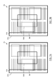
- FIGs. 5A to 7C and 9A to 10D show three different cropping windows 32a to 32c that can be read out from the image 24 of the working area and outputted by the image sensor.
- Each cropping window 32a to 32c has a different size, thus corresponding to a different number of the output pixels being outputted by the image sensor.
- the cropping window 32a to 32c may correspond to the entire image 24 of the working area (e.g., cropping window 32c) or to a partial region thereof (e.g., cropping windows 32a and 32b). It will be understood that, the image sensor may be configured to output the cropping window in any one of a plurality of pixel resolutions, which may differ from those of the exemplary cropping windows 32a to 32c illustrated in FIGs. 5A to 7C and 9A to 10D .
- the image sensor 22 includes a windowing module 34 configured to move, in real-time, the cropping window 32a to 32c within the image 24 of the working area 26.
- the windowing module 34 allows both a digital and live panning of the cropping window 32a to 32c across the image 24 by outputting, in real-time, the output pixels of the array 30 corresponding to the desired cropping window 32a to 32c.
- the live panning system 20 also includes a processing unit 28.
- processing unit is understood to refer to a functional entity of the live panning system that monitors viewing instructions from a user selecting a region of interest within the image and that communicates those viewing instructions to various elements of the live panning system.
- the processing unit may also control and execute, at least partially, the operations required to provide the live representation of the portion of the working area.
- the processing unit 28 is preferably connected to various elements of the live panning system 20 such as the image sensor 22 and the display unit 40 via various input/output (I/O) communication ports, such as camera ports and display ports.
- I/O input/output
- the processing unit 28 may be implemented as a single unit or a plurality of interconnected processing sub-units and may be embodied by or be part of a microprocessor, a central processing unit (CPU), a processing core, a microcontroller, a system on a chip (SoC), a digital signal processor (DSP), a programmable logic device, or by any other processing resource or any combination of such processing resources configured to operate collectively as a processing unit.
- this terminology should not be construed so as to limit the scope or application of the invention.
- the processing unit 28 may include a plurality of modules, sub-modules, routines, components, communication ports, software and the like cooperating together in order to accomplish a particular function. It will be further understood that the subdivision into such modules is made from a conceptual standpoint only and that, in practice, a given hardware or software component may be shared by different modules, and that components of different modules may be combined together physically or logically without departing from the scope of the present invention.
- the various physical components of the processing unit 28 and the interconnections therebetween can be disposed on an integrated circuit (IC) die, which can be mounted onto a printed circuit board (PCB).
- IC integrated circuit
- PCB printed circuit board
- the processing unit 28 of FIG. 4 is configured to monitor and receive requests and instructions from a user, preferably via an input interface 44 such as the one shown in FIG. 1 .
- the processing unit 28 analyzes the requests and communicates with and/or instructs the different modules and components of the live panning system 20 to provide the desired live representation of the portion of the working area.
- the processing unit 28 monitors viewing instructions from the user selecting a region of interest within the image, which corresponds to the portion of the working area.
- region of interest refers to a region of the image of the working area (e.g., an area in pixels ⁇ pixels of the image) that contains information of interest to a user. It will be understood that the region of interest may correspond to a fraction or the entirety of the image of the working area. More specifically, the region of interest 36 in FIGs. 5A, 5B and 5D corresponds respectively to the portion 38 of the working area 26 of FIGs. 8A to 8C whose live representation 42 is provided to the user as a magnified video stream on the display unit 40. Throughout the drawings, as seen in FIGs. 5A to 7C and 9A to 10D described below, the region of interest 36 is outlined by a dashed rectangle inscribed in the image 24 of the working area 26. However, the region of interest 36 may assume other shapes in other embodiments.
- the processing unit 28 dynamically communicates with the windowing module 34 such that the cropping window 32a to 32c outputted by the image sensor 22 always encompasses the region of interest 36, as shown in FIGs. 5A to 7C and 9A to 10D described below.
- the processing unit 28 will transmit that information, in real-time, to the windowing module 34 of the image sensor 22.
- the windowing module 34 will move the cropping window 32a within the image 24 until the cropping window 34 encompasses the new region of interest 36 (see, e.g., FIG. 5D ).
- the processing unit 28 communicates with the windowing module 34, which in turn outputs the requested pixels of the pixel array 30 to form the cropping window 32a to 32c.
- the processing unit can communicate that information to the windowing module, which in turn will increase the size of the cropping window outputted thereby.
- the windowing module 34 may be configured to change, in real-time, a size of the cropping window such that the cropping window always encompasses the region of interest. This is exemplified in FIGs. 9A to 9D , where the cropping window outputted by the image sensor changes from the cropping window 32a to the cropping window 32c in response to instructions received from the user to increase the size of the region of interest 36.
- processing unit is limited to communicating the viewing instructions entered by the user to the windowing module
- processing unit can also instruct and/or control, at least partially, the windowing module to move and/or change the size of the cropping window.
- processing unit can communicate the viewing instructions received from the user either directly to the windowing module or via one or more intermediate components of the live panning system.
- the live panning system 20 may also include a video engine unit 60.
- the video engine unit 60 is in communication with the image sensor 22 and receives therefrom the pixel data of the output pixels corresponding to the cropping window outputted by the image sensor 22.
- the video engine unit 60 is configured to read out, in real-time, the pixel data of a number of pixels of interest from the output pixels to generate a video stream of interest.
- the pixels of interest corresponds to the region of interest 36 of the image 24 which is identified by the user, as shown in FIGs. 5A to 7C and 9A to 10D .
- the video engine unit 60 preferably outputs the video stream of interest at a frame rate equal to the frame rate of the sensor video stream which, as mentioned above, may but need not be equal to 30 or 60 fps.
- the operations performed by the video engine unit are based on the viewing instructions received from the processing unit.
- the processing unit not only communicates the viewing instructions to the video engine unit but can also trigger and control, at least to some extent, the operations executed by the video engine unit.
- the processing unit may communicate with the windowing module of the image sensor indirectly via the video engine unit (i.e., in such embodiments, the processing unit would not be in direct communication with the windowing module of the image sensor).
- the video engine unit is described below as including different modules, each associated with one or more different functions. It will be readily understood by one of ordinary skill in the art that, in practice, each module may include a plurality of sub-modules, routines, components, communication ports, software and the like cooperating together in order to accomplish the corresponding function.
- the processing unit described above it will be understood that the video engine unit may be implemented as a single unit or a plurality of interconnected processing sub-units configured to operate collectively as a video engine unit.
- Typical modern video engines are imaging systems composed of both hardware and software modules. Hardware modules are dedicated to various image processing tasks (video conversion, noise filtering, scaling) whereas software modules allow configuration of the hardware modules and sequencing of the imaging operations in a real-time operating system environment.
- the video engine unit 60 includes a cropping module 62 and a scaling module 64, both of which are in communication with the processing unit 28.
- the cropping module 62 corresponds to the functional entity of the video engine unit 60 that receives, for example over a CSI-2 bus, the cropping window from the image sensor 22 and that crops, in response to the viewing instructions received from the processing unit 28, the cropping window such that only the pixels corresponding to the region of interest 36 are kept in the video stream of interest.
- the cropping module 62 can move, in real-time, the region of interest 36 within the cropping window on account of a request from the user panning the region of interest 36 across the image 24.
- the cropping module 62 of the video engine unit 60 makes it possible to digitally and dynamically pan the region of interest within the cropping window across the image by outputting, in real-time, the required output pixels of the array 30 to form the desired cropping window.
- the panning capabilities offered by the cropping module 62 will be described in greater detail below with reference to FIGs. 5A to 8C .
- the cropping module 62 may be also configured to change, in real-time, a size of the region of interest within the cropping window on account of viewing instructions from the user.
- the cropping module 62 may be configured to reduce or enlarge, in real-time, the size of the region of interest within the cropping window on account of zooming instructions from the user.
- the zooming capabilities offered by the cropping module 62 will be described in greater detail below in reference to FIGs. 9A to 11D .
- the pixels of interest outputted by the cropping module 62 as the video stream of interest are received by the scaling module 64.
- the scaling module 64 is configured to scale the video stream of interest in accordance with a pixel resolution supported by the display unit 40.
- the scaling module 64 may for example be embodied by devices known as resizers, or scalers.
- the scaling module 64 may be in charge of the data buffering, horizontal and vertical rescaling (for example up-scaling for a zoom-in operation or down-scaling for zoom-out operation) and output generation. It will be understood that in some embodiments, the cropping module 62 and the scaling module 64 may be embodied by the same physical module.
- the live panning system 20 may further include a display unit 40.
- the display unit 40 displays, in real-time and at a display frame rate, a magnified video stream of the region of interest identified by the user.
- the magnified video stream is based on the video stream of interest generated by the video engine unit 60, and thus on the sensor video stream generated by the image sensor 22.
- the magnified video stream displayed by the display unit 40 corresponds to the live representation 42 of the portion 38 of the working area 26.
- the display unit 40 is a monitor mounted on a display support 66 of the frame structure 52.
- the display unit 40 may be embodied by any type of display technology, such as liquid crystal display (LCD), light-emitting diode (LED), organic LED (OLED), plasma display panel (PDP), light-emitting polymer display (LPD) or active-matrix OLED (AMOLED) technology.
- LCD liquid crystal display
- LED light-emitting diode
- OLED organic LED
- PDP plasma display panel
- LPD light-emitting polymer display
- AMOLED active-matrix OLED
- the display unit 40 in FIGs. 1 and 2 can be embodied by a monitor using LCD display technology with LED backlight and having a 20-inch or 24-inch diagonal screen and a resolution of 0.92 megapixels corresponding to an array size of 1280 ⁇ 720 pixels.
- exemplary pixel resolutions for the display unit 40 include, without being limited to, 1600 ⁇ 900 pixels (e.g., for a 20-inch screen) or 1920 ⁇ 1080 pixels (e.g., for a 24-inch screen).
- the display frame rate of the display unit 40 can be equal to 60 fps. It will be understood, however, that these parameters of the display unit 40 could be varied in other embodiments without departing from the scope of the invention.
- the live panning system 20 is provided in a handheld device 58.
- the display unit 40 may have a diagonal measurement of about 5 inches and a resolution of 0.384 megapixels, corresponding to an array size of 800 ⁇ 480 pixels.
- the live panning system may optionally include a shared memory 68 and a display controller 70.
- the shared memory 68 may be used by the video engine unit 60 to temporarily store the frames of the video stream of interest.
- the shared memory 68 may be used to either duplicate or skip frames of the video stream of interest in embodiments where the frame rate of the video stream of interest differs from the frame rate of the display unit 40.
- the display controller 70 may be used to read back the frames of the video stream of interest from the shared memory 68 and to drive the display unit 40 at the display frame rate of 60 fps, for example via a digital visual interface (DVI), a high-definition multimedia interface (HDMI) or a parallel interface.
- DVI digital visual interface
- HDMI high-definition multimedia interface
- HDMI high-definition multimedia interface
- Display Port are other display interfaces widely used.
- the display unit 40 receives frames representing the region of interest identified by the user from the display controller 70 and generates therefrom the magnified video stream corresponding to the live representation of the portion of the working area.
- the live panning system 20 also include an input interface 44 in communication with the processing unit 28 to allow the user to act on the live representation 42 of the portion 38 of the working area 26.
- the input interface 44 is shown adjacent the working area 26 on the bottom platform 56, at a position easily accessible to the user, but one of ordinary skill in the art will readily understand that the input interface 44 could be provided at a different location without departing from the scope of the invention.
- the input interface may be provided on a remote control connected directly or wirelessly to the frame structure 52.
- the communication between the processing unit 28 and input interface 44 can be accomplished through a wired connection or wirelessly.
- the input interface 44 includes a touchpad 72.
- the touchpad 72 may be embodied by any suitable technology and may be responsive to typical touch commands such as a pan gesture, a swipe gesture, a tap gesture and a pinch-and-zoom gesture.
- the input interface 44 may further or alternatively include at least one control button 74. Moreover, in other embodiments, additional control buttons may also be used to allow the user to control the live panning system 20. Further embodiments for the input interface may include a mouse, wheel, track ball or joystick or combinations of the above.
- the display unit 40 of the handheld device 58 may, in addition to providing an output interface for displaying the live representation 42 of the portion 38 of the working area 26, include an input interface 44 taking input from a user based on haptic and/or tactile contact.
- the display unit 40 includes, on at least a portion thereof, a touch screen including a touch-sensitive surface.
- image sensors such as CMOS sensors can generally be programmed to output video streams at a particular frame rate and frame size. These two parameters may be respectively expressed in terms of a number of frames per second (fps) and a number of pixels per frame. The product of the frame size multiplied by the frame rate yields a quantity expressed in pixels per second, which corresponds to the output pixel rate of the image sensor.
- fps frames per second
- the product of the frame size multiplied by the frame rate yields a quantity expressed in pixels per second, which corresponds to the output pixel rate of the image sensor.
- the output pixel rate of an image sensor such as a CMOS sensor cannot generally be increased beyond a certain value, referred to herein as the "maximum output pixel rate" of the image sensor.
- the maximum output pixel rate represents a physical limit characterizing the maximum number of pixels that can be outputted by the image sensor over a given period of time. It is known in the art that the maximum output pixel rate of common high-resolution CMOS sensors generally does not exceed 250 MHz (or, equivalently, 250 megapixels per second), although the maximum may of course evolve with available technologies.
- the case of an image sensor 22 having a resolution of 8 megapixels arranged in an array of 3264 ⁇ 2448 pixels can be used as an example.
- outputting the pixel data from all pixels of the array 30 at the preferred sensor frame rate of 60 fps requires an output pixel rate of 480 megapixels per second, which exceeds significantly the maximum output pixel rate of common high-resolution CMOS sensors.
- embodiments of the live panning system rely on window cropping and, optionally, on pixel binning, skipping or scaling.
- the image sensor 22 is capable of reading out and outputting the pixel data of only a limited number of output pixels from the array 30 above a certain frame rate.
- the output pixels outputted by the image sensor 22 define a cropping window which has a smaller frame size than the image of the entire working area. For example, as shown in FIGs.
- the cropping window 32a has a frame size of 1.57 megapixels arranged in an array of 1632 ⁇ 960 pixels, so that outputting the pixel data of the output pixels of the cropping window 32a at the preferred sensor frame rate of 60 fps requires an output pixel rate of about 94 megapixels per second, which is achievable by existing high-resolution image sensors.
- instructing the image sensor to output a cropping window that covers a partial region of the image of the working area may be advantageous when the live representation has a relatively high magnification level such that the region of interest identified by the user is also restricted to a relatively small area of the image.
- Window cropping as described above can be especially useful at relatively high magnification levels (or equivalently for relatively small regions of interest within the image).
- the image sensor outputs the cropping window in an output mode referred to herein as a "full-pixel mode", wherein the image sensor outputs the pixel data of all the output pixels in the cropping window.
- the image sensor generally has to output the pixel data of all the pixels of the array (see, e.g., FIGs. 7A to 7C ) or of a substantial fraction thereof (see, e.g., FIGs. 6A to 6D ) in order to provide the live representation of the portion of the working area that corresponds to the region of interest identified by the user.
- the image sensor 22 such as that of FIG. 4 , may be configured to output the cropping window in an output mode referred to herein as a "reduced-pixel mode". In the reduced-pixel mode the image sensor 22 outputs a reduced version of the pixel data of the output pixels in the cropping window.
- the reduced-pixel mode includes a binned-pixel mode wherein the image sensor outputs binned pixel data each corresponding to a combination of the pixel data of a cluster of the output pixels.
- pixel binning may be achieved, for example, by averaging the voltage levels of adjacent pixels within the array. For example, in a 2 ⁇ 2 binning process, the output pixels defining the cropping window outputted by the image sensor are grouped in clusters of four pixels. The pixel data of the output pixels of each cluster are then averaged to yield binned pixel data.
- pixel binning in addition to reducing the output resolution of the image sensor, also offers the added advantage of increasing the signal-to-noise in the image data outputted by the image sensor.
- the cropping window 32a which has a resolution of 8 megapixels (3264 ⁇ 2448 pixels) can be outputted at a lower resolution of 2 binned megapixels (1632 ⁇ 1224 binned pixels), therefore allowing to keep a frame rate of 30 fps without exceeding the maximum output pixel rate of conventional image sensors.
- the image sensor 22 has been described as being configured to apply a 2 ⁇ 2 binning process, it may alternatively or additionally be configured to apply any suitable type of binning process including vertical binning, horizontal binning, and the like.
- typical current sensors are equipped with a Bayer filter which creates 2 ⁇ 2 clusters of pixel including two green pixels, one red pixel and one blue pixel.
- binning and cropping modes that can be supported are 2 ⁇ 2, 4 ⁇ 4 and 16 ⁇ 16 modes.
- the image sensor 22 may be configured to switch between different binning modes during image acquisition.
- the reduced-pixel mode may include a skipped-pixel mode wherein the image sensor outputs the pixel data of only a subset of the output pixels.
- the image sensor 22 is configured to only output certain pixels inside the cropping window, such as every other pixel, every three pixels, and so forth.
- Other possible skipping modes include two, four and sixteen skipped-pixel modes.
- the reduced-pixel mode may include a scaled-pixel mode wherein the image sensor outputs a rescaled cropping window having a different pixel resolution than the cropping window (typically a smaller pixel resolution), but representing the same portion of the image as the output pixels of the cropping window.
- the scaling of the output pixels to yield the rescaled cropping window can be performed using various techniques known to one of ordinary skill in the art.
- one of the output modes of the image sensor 22 can be selected as a selected output mode, that is, one of the full-pixel mode and the reduced-pixel mode.
- the selection of the selected output mode may be controlled by the image sensor 22 itself (e.g., the windowing module 34), by the processing unit 28 receiving the viewing instructions, by the video engine unit, by a combination thereof or by another component of the live panning system 20.
- the selected output mode of the image sensor 22 can be selected based on: (i) the number of the output pixels in the cropping window; (ii) the desired sensor frame rate of the image sensor; and (iii) the maximum output pixel rate of the image sensor.
- the selected output mode may be the full-pixel mode if the product of the number of output pixels in the cropping window multiplied by the desired sensor frame rate is equal to or less than the maximum output pixel rate of the image sensor.
- the selected output mode may be the reduced-pixel mode if the product of the number of output pixels in the cropping windows multiplied the desired sensor frame rate of the image sensor is greater than the maximal output pixel rate of the image sensor.
- the processing unit 28 instructs the image sensor 22 to output one of the cropping windows 32a to 32c depending on the magnification level set by the user. More specifically, in order to provide the desired magnification level at an optimal sensor frame rate, the selected output mode of the image sensor and the frame size of the cropping windows 32a to 32c can be selected as indicated in TABLE 1 below.
- TABLE 1 the parameters of TABLE 1 are given by way of example only, and that the number and parameters of the cropping windows outputted by the image sensor as a function of viewing instructions provided by a user may differ in other embodiments of the live panning system.
- the cropping window could be outputted in a full-pixel mode down to a magnification level of 1X to 3X if the sensor frame rate is reduced below 30 fps (e.g., 20 fps).
- TABLE 1 Parameters of cropping windows outputted by the image sensor for different ranges of magnification level, in accordance with an embodiment
- Sensor frame rate (fps) 32a 6X to 20X Full-pixel 1632 ⁇ 960 60 32b 3X to 6X Full-pixel 3264 ⁇ 1920 30 32c 1 X to 3X Reduced-pixel (2 ⁇ 2 binning) 1632 ⁇ 1224 30
- FIGs. 5A to 7C provide schematic representations of the image 24 of the entire working area 26 shown in FIGs. 8A to 8C and having an object 48 disposed thereon.
- the object 48 is a letter-sized document including images and textual content.
- the image 24 has a resolution of 8 megapixels arranged in an array of 3264 ⁇ 2448 pixels.
- FIGs. 5A to 7C also illustrate three exemplary cropping windows 32a to 32c that can be outputted by the image sensor 22. The parameters of the cropping windows 32a to 32c are given in TABLE 1.
- the image sensor 22 outputs one of the three cropping windows 32a to 32c based on viewing instructions from a user identifying a region of interest 36 within the image. More specifically, the selection of the appropriate cropping window 32a to 32c is made such that the region of interest 36 is always encompassed within the selected cropping window 32a to 32c. It will be understood that when the region of interest 36 is displayed on a display unit 40 at a given magnification level, a high magnification level on the display unit 40 generally corresponds to a small region of interest 36 within the image 24, and vice versa.
- the display unit 40 has a 24-inch diagonal screen and a resolution of 0.92 megapixels corresponding to an array size of 1280 ⁇ 720 pixels.
- the portion 38 of the working area 26 whose live representation 42 is presented on the display unit 40 is indicated by a dashed rectangle on the document disposed on the working area 26.
- live panning is performed either by the windowing module 34 of the image sensor or by the cropping module 62 of the video engine unit 60, in a manner such that the region of interest 36 is always encompassed by the selected cropping window 32a to 32c.
- the region of interest 36 within the image 24 that the user wishes to view corresponds to the portion 38 of the working area 26 whose live representation is displayed on the display unit 40 at a magnification level of 15X, as shown in FIG. 8A .
- the image sensor 22 shown in FIG. 4 outputs the cropping window 32a (see TABLE 1), which encompasses and is centered on the region of interest 36 identified by the user. More specifically, the cropping window 32a has a resolution of 1632 ⁇ 960 pixels and is outputted in the full-pixel mode at 60 fps.
- the processing unit 28 in FIG. 4 communicates these instructions to the cropping module 62 of the video engine unit 60, and the cropping module 62 moves, in real-time, the region of interest 36 within the cropping window 32a. More specifically, based on viewing instructions from the user, the processing unit 28 in FIG. 4 communicates to the cropping module 62 which of the output pixels of the cropping window 32a are to be outputted as the pixels of interest.
- the live representation 42 provided on the display unit 40 corresponds to the region of interest 36 identified in FIG. 5B .
- the user continues to pan the region of interest 36 toward the top portion of the image 24, up to a position where the region of interest 36 lies partially outside the cropping window 32a.
- the windowing module 34 of the image sensor 22 of FIG. 4 moves the cropping window 32a within the image 24 until the region of interest 36 is again encompassed within the cropping window 32a, as shown in FIG. 5D .
- the processing unit 28 communicates to the windowing module 34 of the image sensor 22 which of the pixels of the array 30 are to be outputted as the output pixels and be sent to the video engine unit 60 for further cropping by the cropping module 62.
- the cropping window 32a is moved such that its center coincides, if possible, with the center of the region of interest 36.
- the live representation 42 provided on the display unit 40 corresponds to the region of interest 36 in FIG. 5D .
- the live panning performed by the live panning system is accomplished without physically displacing the field of view 46 of the image sensor 22 with respect to the working area 26, as may be seen from FIGs. 8A to 8C .
- panning operations made possible by embodiments of the live panning system involve moving, in real-time, the region of interest 36 within the image 24 of the entire working area 26 such the live representation 42 of the portion 38 of working area 26 is provided to the user with negligible or insignificant time lag or delay.
- the cropping window is preferably moved by the windowing module of the image sensor only when the region of interest moves outside the boundaries of the currently outputted cropping window.
- the panning operations are preferably performed by the cropping module of the video engine unit.
- the output pixels outputted by the image sensor remains the same and only the pixels of interest outputted by the video engine unit are modified in response to panning instructions by the user.
- the image sensor outputs the cropping window 32b.
- the parameters of the cropping window 32b are given in TABLE 1. More specifically, the cropping window 32b has a resolution of 3264 ⁇ 1920 pixels and is outputted in the full-pixel mode at 30 fps.
- the region of interest 36 that the user wishes to view is encompassed by the cropping window 32b.
- the region of interest 36 is panned toward the top portion of the image 24, but remains within the cropping window 32b such that it is not necessary to move the cropping window 32b.
- the cropping module 62 of the video engine unit 60 moves, in real-time, the region of interest 36 within the cropping window 32b. More specifically, based on viewing instructions from the user, the processing unit 28 in FIG. 4 communicates to the cropping module 62 which of the output pixels of the cropping window 32b are to be outputted as the pixels of interest.
- the user pan the region of interest 36 toward the left margin of the image 24, to a position where the region of interest 36 lies partially outside the cropping window 32b.
- the windowing module 34 of the image sensor 22 in FIG. 4 moves the cropping window 32b within the image 24 until the region of interest 36 is again encompassed within the cropping window 32b, as shown in FIG. 6D .
- the image sensor outputs the cropping window 32c whose parameter are given in TABLE 1. More specifically, the cropping window 32c has a resolution of 1632 ⁇ 1224 pixels and is outputted in the reduced-pixel mode (i.e., in a 2 ⁇ 2 binning mode) at 30 fps. It is to be noted that, in this case, the size of the cropping window 32c coincides with that of the entire image 24 of the working area. It will be understood that when the region of interest 36 covers the entire image 24 or a substantial fraction thereof, the cropping window 32c is generally outputted at low magnification levels, as shown, for example, in FIGs. 1 and 2 . The region of interest 36 that the user wishes to view is encompassed by the cropping window 32c.
- the region of interest 36 is panned toward the right margin of the image 24, but remains within the cropping window 32c such that it is not necessary to move the cropping window 32c.
- the cropping module 62 of the video engine unit 60 of FIG. 4 moves, in real-time, the region of interest 36 within the cropping window 32c by selecting which of the output pixels of the cropping window 32c are to be outputted as the pixels of interest.
- the user pans the region of interest 36 until the region of interest 36 reaches the right boundary of the image 24.
- FIGs. 9A to 10D provide schematic representations of the image 24 of the entire working area 26 shown in FIGs. 11A to 11D and having an object 48 disposed thereon.
- the object 48 is a letter-sized document including images and textual content.
- the image 24 in FIGs. 9A to 10D has a resolution of 8 megapixels arranged in an array of 3264 ⁇ 2448 pixels.
- the parameters of the cropping windows 32a to 32c exemplified in FIGs. 9A to 10D are given in TABLE 1.
- the image sensor 22 outputs of FIG. 4 one of the three cropping windows 32a to 32c based on viewing instructions from a user identifying a region of interest 36 within the image. More specifically, the selection of the appropriate cropping window 32a to 32cis made such that the region of interest 36 is always encompassed within the selected cropping window 32a to 32c. Among all cropping windows available, the smallest cropping window encompassing the region of interest 36 is preferably used because it generally permits better resolution and better frame rate. As in FIGs. 8A to 8C , the exemplary display unit 40 in FIGs.
- 11A to 11D has a 24-inch diagonal screen and a resolution of 0.92 megapixels corresponding to an array size of 1280 ⁇ 720 pixels. Moreover, the portion 38 of the working area 26 whose live representation 42 is presented on the display unit 40 is indicated by a dashed rectangle on the document disposed on the working area 26.
- the region of interest 36 within the image 24 that the user wishes to view corresponds to the portion 38 of the working area 26 whose live representation is displayed on the display unit 40 at a magnification level of 15X, as shown in FIG. 11A .
- the image sensor 22 shown in FIG. 4 outputs the cropping window 32a (see TABLE 1), which encompasses and is centered on the region of interest 36 identified by the user.
- FIG. 9B the user has zoomed out to view a larger portion 38 of the working area 26.
- the size of the region of interest 36 is increased accordingly, to a point where it does not fit inside the cropping window 32a anymore. Therefore, upon receiving the zooming instructions from the user, the processing unit 28 in FIG. 4 communicates these instructions to the windowing module 34, which in turn outputs, in real-time, the cropping window 32b in replacement of the cropping window 32a.
- the cropping window 32b is outputted such that its center coincides, if possible with the center of the region of interest 36.
- the processing unit 28 communicates to the windowing module 34 which of the pixels of the array 30 are to be outputted as output pixels.
- the live representation 42 provided on the display unit 40 corresponds to the region of interest 36 identified in FIG. 9B . It may be seen that the magnification level is lower than in FIG. 11A .
- the windowing module 34 of the image sensor 22 in FIG. 4 outputs the cropping window 32c, as shown in FIG. 9C .
- the cropping window 32c is preferably outputted such that its center coincides, if possible, with the center of the region of interest 36.
- the live representation 42 provided on the display unit 40 corresponds to the region of interest 36 identified in FIG. 9C .
- FIG. 9D the user has zoomed out to a point where the width of the region of interest 36 reaches the width of the cropping window 32c and, thus, the width of the image 24.
- the live representation 42 corresponding to the region of interest 36 of FIG. 9C is shown in FIG. 11D .
- the width of the region of interest 36 selected by the user corresponds to the width of the image 24 of the working area, such that the image sensor 22 in FIG. 4 outputs the cropping window 32c.
- FIG. 10B the user has zoomed in onto the image 24.
- the size of the region of interest 36 decreases accordingly, but not to a point where it could fit inside the cropping window 32b.
- the image sensor 22 continues to output the cropping window 32c and the cropping module 62 of the video engine unit 60 to outputs, from the output pixels received from the image sensor 22, the pixels of interest corresponding to the now smaller region of interest 36.
- the scaling module 64 of the video engine unit 60 can also be configured accordingly.
- the windowing module 34 of the image sensor 22 in FIG. 4 outputs the output pixels corresponding to the cropping window 32b, preferably centered on the region of interest 36.
- FIG. 10D the user has zoomed in to a point where the region of interest 36 fits inside the cropping window 32a. Accordingly, the windowing module 34 of the image sensor 22 outputs the output pixels corresponding to the cropping window 32a, preferably centered on the region of interest 36.
- Live panning method for providing a live representation of a portion of a working area
- FIG. 12 shows a flow chart of an embodiment of the live panning method 100, which could, by way of example, be performed with a live panning system such as those illustrated in FIGs. 1 to 3 .
- live panning methods according to embodiments of the invention may be particularly useful when performed with video magnifiers directed to individuals suffering from low vision or other visual impairments.
- video magnifiers for low-vision individuals generally involve displacing the working area to bring different portions of the working area within the field of view of the image sensor.
- panning in conventional video magnifiers may be cumbersome or inefficient, leading to degradation in performance and usability.
- the live panning method according to embodiments of the invention can achieve panning without the user having to physically or mechanically move the image sensor and the working area relative to each other.
- live panning method may be targeted to low-vision individuals
- live panning method could, in general, be used by any person desiring a device capable of panning across an image of a working area in real-time and without having to move the field of view of an image sensor with respect to the working area.
- the live panning method 100 first includes a step 102 of acquiring an image of the entire working area.
- the working area is preferably sufficiently large to allow the image of the entire surface of a document having a standard letter size to be acquired at a distance of less than about 25 cm.
- standard paper sizes include, without being limited to, Letter (215.9 mm ⁇ 279.4 mm), A3 (297 mm ⁇ 420 mm), A4 (210 mm ⁇ 297 mm), A5 (148 mm ⁇ 210 mm), and the like.
- these values and ranges are provided for illustrative purposes only and that embodiments of the live panning method may operate outside these ranges.
- the step 102 of acquiring the image of the entire working area includes acquiring the image at a high-resolution such as, for example, at least 5 megapixels, although lower resolution images could be acquired without departing from the scope of the present invention.
- the live panning method 100 also includes a step 104 of generating a sensor video stream by reading out, at a sensor frame rate, a cropping window within the image.
- the cropping window thus represents one frame of the sensor video stream.
- the sensor frame rate is preferably equal to 30 or, further preferably, to 60 fps in order for the live panning method 100 to provide a live representation of the portion of the working area that remains fluid from the perspective of the human eye.
- any other appropriate values may be used for the sensor frame rate without departing from the scope of the present invention.
- the cropping window may assume a plurality of size or shape, as discussed above in connection with FIGs. 5A to 7C and 9A to 10D .
- the cropping window 32a to 32c may correspond to the entire image 24 of the working area (e.g., cropping window 32c) or to a partial region thereof (e.g., cropping windows 32a and 32b).
- the step 104 of generating the sensor video stream is not limited to a particular size or shape of cropping windows.
- the live panning method 100 further includes a step 106 of monitoring viewing instructions from a user identifying a region of interest within the image corresponding to the portion of the working area.
- the region of interest refers to a region of the image of the working area (e.g., an area in pixels ⁇ pixels of the image) that contains information of interest to a user.
- the region of interest may correspond to a fraction of or to the entire image of the working area.
- the live panning method 100 also includes, on account of the step 106 of monitoring the viewing instructions from the user, a step 108 of moving, in real-time, the cropping window within the image such that the cropping window always encompasses the region of interest.
- a step 108 of moving, in real-time, the cropping window within the image involves digitally panning the cropping window so that it encompasses the new region of interest selected by the user
- the live panning method 100 exemplified in FIG. 12 can include a step 110 of generating a video stream of interest by reading out the region of interest identified by the user within the cropping window at a frame rate preferably equal to the frame rate of the sensor video stream which, as mentioned above, may, but need not, be equal to 30 or 60 fps. It will be understood that the region of interest of the image represents one frame of the video stream of interest.
- the live panning method 100 may further include a step of moving 112, in real-time, the region of interest within the cropping window on account of the viewing instructions from the user.
- the live panning method 100 of FIG. 12 also includes an optional step 114 of displaying, in real-time and at a display frame rate, a magnified video stream of the region of interest identified by the user.
- the magnified video stream is based on the sensor video stream and, in some embodiments, on the video stream of interest.
- the magnified video stream corresponds to the live representation of the portion of the working area.
- the display frame rate can be equal to 60 fps.
- the steps 108 and 112 of respectively moving, in real-time, the cropping window within the image and the region of interest within the cropping window together allow the live panning of the region of interest within the image.
- the step of 108 moving the cropping window within the image is preferably performed only when the region of interest moves outside the boundaries of the currently outputted cropping window.
- the panning operations are preferably carried out by performing the step 112 of moving the region of interest within the cropping window.
- the live panning method 100 can also allow performing live zooming operations by enlarging or reducing the size of the region of interest in response to zooming instructions from the user.
- the live panning method 100 may include a step 116 of changing, in real-time, a size of the cropping window on account of viewing instructions from the user selecting a size of the region of interest such that the cropping window always encompasses the region of interest.
- the live panning method 100 may also include a step 118 of changing, in real-time, a size of the region of interest within the cropping window on account of the viewing instructions from the user.
- steps 116 and 118 of respectively changing, in real-time, the size of the cropping window within the image and the size of the region of interest within the cropping window together allow the live zooming onto or out of the region of interest in response to zooming instructions from the user.
- the step 104 of generating the sensor video stream generally involves selecting the sensor frame rate and the frame size of the cropping window forming the sensor video stream. These two parameters may be respectively expressed in terms of a number of frames per second and a number of pixels per frame, and their product yields a quantity expressed in pixels per second, which corresponds to an output pixel rate.
- the frame size of the cropping window and the sensor frame rate of the sensor video stream are jointly selected so that the output pixel rate does not exceed a maximum output pixel rate imposed characterizing a given embodiment of the live panning method.
- the maximum output pixel rate may represent a physical limit characterizing the maximum number of pixels that can be outputted by a system performing the live panning method.
- the embodiment of the live panning method 100 illustrated in FIG. 12 relies on window cropping, as discussed above, and optionally, on pixel binning or skipping.
- the cropping window read out in the step 104 of generating the sensor video stream includes a number of output pixels, each having pixel data associated therewith.
- the step 104 of generating the sensor video stream further includes outputting the cropping window in any one of a plurality of output modes. More specifically, generating 104 the sensor video stream may include outputting the cropping window in a full-pixel mode 120 wherein the pixel data of all the output pixels in the cropping window are outputted or, referring to the alternative embodiment of FIG. 13 , outputting the cropping window in a reduced-pixel mode 122 wherein a reduced version of the pixel data of the output pixels in the cropping window are outputted.
- selecting between the full-pixel mode and the reduced-pixel mode may be based on criteria such as (i) a required size of the cropping window; (ii) a desired sensor frame rate of the sensor video stream; and (iii) a maximum output pixel rate associated with a particular embodiment of the live panning method.
- the full-pixel mode may be useful at high magnification levels, where the region of interest corresponds to a relatively small fraction of the image of the working area.
- the reduced-pixel mode may be useful at low magnification levels, where the region of interest corresponds to a relatively large fraction of the image of the working area.
- the reduced-pixel mode may include, for example, a binned-pixel mode wherein outputting 122 the cropping window includes outputting binned pixel data each corresponding to a combination of the pixel data of a cluster of the output pixels, or a skipped-pixel mode wherein outputting 122 the cropping window includes outputting the pixel data of only a subset of the output pixels.
- Some advanced CMOS sensor could also provide scaling capabilities in addition to pixel binning and pixel skipping.
Landscapes
- Engineering & Computer Science (AREA)
- Signal Processing (AREA)
- Multimedia (AREA)
- General Physics & Mathematics (AREA)
- Theoretical Computer Science (AREA)
- Physics & Mathematics (AREA)
- Business, Economics & Management (AREA)
- Educational Technology (AREA)
- Educational Administration (AREA)
- Health & Medical Sciences (AREA)
- General Health & Medical Sciences (AREA)
- Audiology, Speech & Language Pathology (AREA)
- Studio Devices (AREA)
- Closed-Circuit Television Systems (AREA)
- Image Processing (AREA)
Applications Claiming Priority (1)
| Application Number | Priority Date | Filing Date | Title |
|---|---|---|---|
| US201361814455P | 2013-04-22 | 2013-04-22 |
Publications (2)
| Publication Number | Publication Date |
|---|---|
| EP2797308A2 true EP2797308A2 (fr) | 2014-10-29 |
| EP2797308A3 EP2797308A3 (fr) | 2015-01-07 |
Family
ID=50639263
Family Applications (1)
| Application Number | Title | Priority Date | Filing Date |
|---|---|---|---|
| EP20140165162 Withdrawn EP2797308A3 (fr) | 2013-04-22 | 2014-04-17 | Système et procédé de panoramique en direct |
Country Status (3)
| Country | Link |
|---|---|
| US (1) | US9426431B2 (fr) |
| EP (1) | EP2797308A3 (fr) |
| CA (1) | CA2849563A1 (fr) |
Families Citing this family (10)
| Publication number | Priority date | Publication date | Assignee | Title |
|---|---|---|---|---|
| USD763940S1 (en) * | 2014-04-18 | 2016-08-16 | Technologies Humanware Inc. | Handheld electronic magnifier for low vision users |
| JP6442261B2 (ja) * | 2014-06-05 | 2018-12-19 | キヤノン株式会社 | 撮像素子及び撮像装置、及びその制御方法 |
| US10217187B2 (en) | 2015-06-05 | 2019-02-26 | Qatar Foundation For Education, Science And Immunity Development | Method for dynamic video magnification |
| EP3316109B1 (fr) * | 2016-10-28 | 2019-09-04 | TeamViewer GmbH | Procédé mis en oeuvre par ordinateur pour commander un dispositif à distance au moyen d'un dispositif local |
| CN109743610A (zh) * | 2018-11-30 | 2019-05-10 | 新视家科技(北京)有限公司 | 视频流的显示方法及其装置、电子设备、计算机可读介质 |
| US11809998B2 (en) * | 2020-05-20 | 2023-11-07 | Qualcomm Incorporated | Maintaining fixed sizes for target objects in frames |
| US20220182561A1 (en) * | 2020-10-04 | 2022-06-09 | Digital Direct Ir, Inc. | Wide field of view imaging system for vehicle artificial intelligence system |
| JP7076061B1 (ja) | 2020-12-23 | 2022-05-27 | ダイキン工業株式会社 | 作業者端末、動画像処理方法及び動画像処理プログラム |
| CN116157771A (zh) * | 2021-09-10 | 2023-05-23 | 北京小米移动软件有限公司 | 图像的处理方法及其装置 |
| US20260089255A1 (en) * | 2024-09-24 | 2026-03-26 | Eschenbach Optik of America | Wifi coupled low vision camera |
Family Cites Families (25)
| Publication number | Priority date | Publication date | Assignee | Title |
|---|---|---|---|---|
| US6731326B1 (en) * | 1999-04-06 | 2004-05-04 | Innoventions, Inc. | Low vision panning and zooming device |
| US6781606B2 (en) * | 1999-05-20 | 2004-08-24 | Hewlett-Packard Development Company, L.P. | System and method for displaying images using foveal video |
| AU2001289914A1 (en) * | 2000-09-25 | 2002-04-02 | Sensovation Ag | Image sensor device, apparatus and method for optical measurements |
| JP2002359774A (ja) * | 2001-03-30 | 2002-12-13 | Fuji Photo Film Co Ltd | 電子カメラ |
| US20020191031A1 (en) * | 2001-04-26 | 2002-12-19 | International Business Machines Corporation | Image navigating browser for large image and small window size applications |
| NZ518092A (en) * | 2002-03-28 | 2004-11-26 | Pulse Data Internat Ltd | Low vision video magnifier viewing apparatus having digital zoom feature |
| JP4080248B2 (ja) * | 2002-05-31 | 2008-04-23 | 富士通株式会社 | 画像読取装置 |
| KR100617681B1 (ko) * | 2003-04-15 | 2006-08-28 | 삼성전자주식회사 | 휴대용 단말기의 회전키 장치 사용 방법 |
| JP4442112B2 (ja) * | 2003-04-16 | 2010-03-31 | ソニー株式会社 | 画像表示装置及び画像ぶれ防止方法 |
| US7773115B2 (en) * | 2004-12-15 | 2010-08-10 | Texas Instruments Incorporated | Method and system for deblurring digital camera images using reference image and motion estimation |
| TWI302671B (en) * | 2005-06-27 | 2008-11-01 | Compal Electronics Inc | A portable electronic device with the ability of real time inserting image data into a menu |
| JP4869978B2 (ja) | 2006-03-28 | 2012-02-08 | 富士フイルム株式会社 | 画像記録装置、画像記録方法、および画像記録プログラム |
| US7746391B2 (en) * | 2006-03-30 | 2010-06-29 | Jai Pulnix, Inc. | Resolution proportional digital zoom |
| US8726194B2 (en) * | 2007-07-27 | 2014-05-13 | Qualcomm Incorporated | Item selection using enhanced control |
| US9335912B2 (en) * | 2007-09-07 | 2016-05-10 | Apple Inc. | GUI applications for use with 3D remote controller |
| JP5096302B2 (ja) * | 2008-12-12 | 2012-12-12 | 株式会社キーエンス | 撮像装置 |
| WO2011065960A1 (fr) * | 2009-11-30 | 2011-06-03 | Hewlett-Packard Development Company, L.P. | Stabilisation d'un sujet d'intérêt dans une vidéo capturée |
| US9600760B2 (en) * | 2010-03-30 | 2017-03-21 | Disney Enterprises, Inc. | System and method for utilizing motion fields to predict evolution in dynamic scenes |
| US8767030B2 (en) * | 2011-04-07 | 2014-07-01 | Tara Chand Singhal | System and method for a grooming mirror in a portable electronic device with a user-facing camera |
| US8724854B2 (en) * | 2011-04-08 | 2014-05-13 | Adobe Systems Incorporated | Methods and apparatus for robust video stabilization |
| US20130142381A1 (en) * | 2011-12-02 | 2013-06-06 | Field Tested Software Llc | Real time spectroscopy processing and analysis system |
| US8918453B2 (en) * | 2012-01-03 | 2014-12-23 | Qualcomm Incorporated | Managing data representation for user equipments in a communication session |
| GB2499635B (en) * | 2012-02-23 | 2014-05-14 | Canon Kk | Image processing for projection on a projection screen |
| TWI460668B (zh) * | 2012-07-30 | 2014-11-11 | Faraday Tech Corp | 影像擷取系統與方法 |
| US20140301477A1 (en) * | 2013-04-07 | 2014-10-09 | Sharp Laboratories Of America, Inc. | Signaling dpb parameters in vps extension and dpb operation |
-
2014
- 2014-04-17 CA CA 2849563 patent/CA2849563A1/fr not_active Abandoned
- 2014-04-17 EP EP20140165162 patent/EP2797308A3/fr not_active Withdrawn
- 2014-04-18 US US14/256,061 patent/US9426431B2/en active Active
Also Published As
| Publication number | Publication date |
|---|---|
| EP2797308A3 (fr) | 2015-01-07 |
| CA2849563A1 (fr) | 2014-10-22 |
| US20140313329A1 (en) | 2014-10-23 |
| US9426431B2 (en) | 2016-08-23 |
Similar Documents
| Publication | Publication Date | Title |
|---|---|---|
| US9426431B2 (en) | Live panning system and method for reading out a cropping window of pixels from an image sensor | |
| JP5499039B2 (ja) | 対象物を撮像するためのシステムおよび方法 | |
| US10877262B1 (en) | Magnification glasses with multiple cameras | |
| US6731326B1 (en) | Low vision panning and zooming device | |
| US10129520B2 (en) | Apparatus and method for a dynamic “region of interest” in a display system | |
| EP2747412A2 (fr) | Système d'agrandissement | |
| US20050162512A1 (en) | Low vision video magnifier | |
| EP4175280A1 (fr) | Procédé de photographie d'images et dispositif électronique | |
| US8743278B2 (en) | Portable magnifying apparatus having multi angular positioned handle | |
| JP2013148599A (ja) | 表示装置 | |
| US20040036663A1 (en) | System and method for an image reader with electronic travel | |
| US20090256689A1 (en) | Image display apparatus and image display method | |
| CN102625066A (zh) | 图像处理装置和图像处理方法 | |
| EP3138282B1 (fr) | Système et procédé de traitement d'un signal vidéo avec une latence réduite | |
| US8373639B2 (en) | Device and method for adjustment of a work place illumination | |
| KR100666422B1 (ko) | 저 시력 장애인용, 휴대용 영상 확대장치 | |
| WO2003079666A1 (fr) | Systeme et procede pour un lecteur d'images a deplacement electronique | |
| CN114690407A (zh) | 一种视野补偿方法及使用其的近眼显示设备 | |
| KR20160127945A (ko) | 고령자 시각인지 특성을 고려한 Full HD급 고속 영상처리 알고리즘 및 스마트 영상 확대 장치 | |
| KR20110006210U (ko) | 디지털 액자에 카메라 거울방식을 적용한 통합 거울액자 |
Legal Events
| Date | Code | Title | Description |
|---|---|---|---|
| PUAI | Public reference made under article 153(3) epc to a published international application that has entered the european phase |
Free format text: ORIGINAL CODE: 0009012 |
|
| 17P | Request for examination filed |
Effective date: 20140417 |
|
| AK | Designated contracting states |
Kind code of ref document: A2 Designated state(s): AL AT BE BG CH CY CZ DE DK EE ES FI FR GB GR HR HU IE IS IT LI LT LU LV MC MK MT NL NO PL PT RO RS SE SI SK SM TR |
|
| AX | Request for extension of the european patent |
Extension state: BA ME |
|
| PUAL | Search report despatched |
Free format text: ORIGINAL CODE: 0009013 |
|
| AK | Designated contracting states |
Kind code of ref document: A3 Designated state(s): AL AT BE BG CH CY CZ DE DK EE ES FI FR GB GR HR HU IE IS IT LI LT LU LV MC MK MT NL NO PL PT RO RS SE SI SK SM TR |
|
| AX | Request for extension of the european patent |
Extension state: BA ME |
|
| RIC1 | Information provided on ipc code assigned before grant |
Ipc: H04N 5/225 20060101ALI20141203BHEP Ipc: H04N 7/18 20060101ALI20141203BHEP Ipc: H04N 5/232 20060101AFI20141203BHEP Ipc: G09B 21/00 20060101ALI20141203BHEP Ipc: H04N 5/262 20060101ALI20141203BHEP Ipc: H04N 1/00 20060101ALI20141203BHEP Ipc: H04N 5/341 20110101ALI20141203BHEP Ipc: H04N 1/387 20060101ALI20141203BHEP Ipc: G06T 3/40 20060101ALI20141203BHEP |
|
| STAA | Information on the status of an ep patent application or granted ep patent |
Free format text: STATUS: THE APPLICATION IS DEEMED TO BE WITHDRAWN |
|
| 18D | Application deemed to be withdrawn |
Effective date: 20150708 |