EP2797373B1 - Procédé, système et dispositif de détermination de sous-trames de transmission - Google Patents
Procédé, système et dispositif de détermination de sous-trames de transmission Download PDFInfo
- Publication number
- EP2797373B1 EP2797373B1 EP13739055.5A EP13739055A EP2797373B1 EP 2797373 B1 EP2797373 B1 EP 2797373B1 EP 13739055 A EP13739055 A EP 13739055A EP 2797373 B1 EP2797373 B1 EP 2797373B1
- Authority
- EP
- European Patent Office
- Prior art keywords
- user equipment
- subframe
- transmission
- transmission subframe
- information
- Prior art date
- Legal status (The legal status is an assumption and is not a legal conclusion. Google has not performed a legal analysis and makes no representation as to the accuracy of the status listed.)
- Active
Links
Images


Classifications
-
- H—ELECTRICITY
- H04—ELECTRIC COMMUNICATION TECHNIQUE
- H04W—WIRELESS COMMUNICATION NETWORKS
- H04W72/00—Local resource management
- H04W72/04—Wireless resource allocation
- H04W72/044—Wireless resource allocation based on the type of the allocated resource
- H04W72/0446—Resources in time domain, e.g. slots or frames
-
- H—ELECTRICITY
- H04—ELECTRIC COMMUNICATION TECHNIQUE
- H04L—TRANSMISSION OF DIGITAL INFORMATION, e.g. TELEGRAPHIC COMMUNICATION
- H04L1/00—Arrangements for detecting or preventing errors in the information received
-
- H—ELECTRICITY
- H04—ELECTRIC COMMUNICATION TECHNIQUE
- H04L—TRANSMISSION OF DIGITAL INFORMATION, e.g. TELEGRAPHIC COMMUNICATION
- H04L1/00—Arrangements for detecting or preventing errors in the information received
- H04L1/0001—Systems modifying transmission characteristics according to link quality, e.g. power backoff
- H04L1/0023—Systems modifying transmission characteristics according to link quality, e.g. power backoff characterised by the signalling
- H04L1/0026—Transmission of channel quality indication
-
- H—ELECTRICITY
- H04—ELECTRIC COMMUNICATION TECHNIQUE
- H04L—TRANSMISSION OF DIGITAL INFORMATION, e.g. TELEGRAPHIC COMMUNICATION
- H04L1/00—Arrangements for detecting or preventing errors in the information received
- H04L1/12—Arrangements for detecting or preventing errors in the information received by using return channel
- H04L1/16—Arrangements for detecting or preventing errors in the information received by using return channel in which the return channel carries supervisory signals, e.g. repetition request signals
- H04L1/18—Automatic repetition systems, e.g. Van Duuren systems
- H04L1/1867—Arrangements specially adapted for the transmitter end
- H04L1/1887—Scheduling and prioritising arrangements
-
- H—ELECTRICITY
- H04—ELECTRIC COMMUNICATION TECHNIQUE
- H04W—WIRELESS COMMUNICATION NETWORKS
- H04W76/00—Connection management
- H04W76/10—Connection setup
- H04W76/14—Direct-mode setup
Definitions
- the embodiments of the present invention relate to the field of communications technologies, and in particular, to a method, a system and an equipment for determining a transmission subframe.
- a wireless communication system is a multiple access system.
- a base station sends, on a downlink, downlink data and/or control information to a user equipment (UE), and receives, on an uplink, uplink data and/or control information sent by the user equipment.
- Communication between the base station and the user equipment may be performed by using a frequency division duplex (FDD) manner or a time division duplex (TDD) manner.
- FDD frequency division duplex
- TDD time division duplex
- a source user equipment first needs to transmit data to a base station or a network, and then the base station or the network transmits the received data to a destination user equipment.
- user equipments close to each other may directly perform data transmission, thereby reducing an overhead of a transmission resource, such as time, a frequency, a code channel, and power, between the user equipment and the base station; and a transmission resource may be multiplexed between different user equipments far away from each other, thereby further increasing resource utilization efficiency, and improving a throughput of the system.
- the base station only allocates transmission resources for communication between the base station and the user equipment, and determines, according to an uplink service load and a downlink service load, allocation of an uplink transmission resource and a downlink transmission resource for the communication.
- transmission resources for direct communication between user equipments are not considered.
- Esseling N et al: "Performance Evaluation of a Fixed Relay Concept for Next Generation Wireless Systems", Personal, Indoor and Mobile Radio Communications, 2004 discloses a method for determining transmission subframes according to the preamble of the claims and further EP0713345 and CN102307060 all disclose methods and systems for determining transmission subframes.
- Embodiments of the present invention provide a method for determining a transmission subframe and a base station, so that allocation of transmission resources for direct communication between user equipments is also considered when transmission resources for data transmission between a user equipment and a base station is allocated to the user equipment, thereby improving system resource utilization efficiency.
- An embodiment of the present invention provides a method for determining a transmission subframe, used for determining a transmission subframe for data transmission between multiple user equipments which directly communicate with each other, and comprising:
- An embodiment of the present invention provides a base station, configured to determine a transmission subframe for data transmission between multiple user equipments which directly communicate with each other, and comprising:
- An embodiment of the present invention provides a method for determining a transmission subframe, so that when multiple user equipments directly communicate with each other, a base station determines a transmission subframe for data transmission between user equipments which directly communicate with each other, and transmission resources for direct communication between user equipments and transmission resources for communication between the base station and each of the user equipments which directly communicate with each other are considered.
- the method in this embodiment is a method executed by the base station, a flowchart is as shown in FIG. 1 , and the method includes:
- uplink information transmitted by each user equipment may include uplink data information and uplink response feedback information, and may further include channel state information, and so on.
- the uplink response feedback information is response feedback information of the user equipment to downlink data transmitted by the base station, and includes: an acknowledge (ACK) message or a non acknowledge (NACK) message. Then transmission resources for the user equipment to transmit the uplink response feedback information are determined according to the downlink data sent by the base station to the user equipment, and the base station may consider requirements such as a service transmission load, a transmission delay and quality of service (QoS) on a downlink communication link from the base station to the user equipment, and determine, according to a preset policy, transmission resources for the user equipment to transmit downlink data.
- QoS quality of service
- the preset policy may include that, if the service transmission load on the downlink communication link in a certain period of time is large, downlink data needs to be sent within preset time after this period of time, so as to further determine sending time and a size of the uplink response feedback information sent by the user equipment within the predetermined time range to the base station. For example, if the base station needs to send the downlink data to the user equipment on an n th transmission subframe, it is determined that the user equipment sends the uplink response feedback information to the base station on an (n+4) th transmission subframe, and occupies a part of time resources of the (n+4) th transmission subframe.
- the predetermined time range may be a frame formed by multiple transmission subframes or a super frame formed by multiple frames.
- the uplink data information may include information such as service data that the user equipment needs to send.
- the base station may consider requirements such as a service transmission load, a transmission delay and QoS on an uplink communication link from the user equipment to the base station, and determine, according to a preset policy, sending time and a size of the uplink data information sent by the user equipment to the base station.
- the preset policy may include that, if the QoS on the uplink communication link within a certain period of time is good, it may be determined that the user equipment sends the uplink data information within this period of time.
- the channel state information is information which is reported periodically or non-periodically by the user equipment and is used to indicate an uplink channel state, and the base station may determine transmission resources for the user equipment to send the channel state information, for example, a transmission subframe on which the user equipment sends the uplink data information and/or the channel state information.
- the base station After determining the sending time and the size of the uplink data information, the uplink response feedback information and/or the channel state information sent by the user equipment, the base station determines the first transmission subframe set R1 of the user equipment. For the second transmission subframe set R2, the base station may consider requirements such as a service transmission load, a transmission delay and QoS on a communications link between the user equipment and another user equipment that directly communicates with the user equipment, and determine, according to a preset policy, sending time and a size of data transmitted by the user equipment to the another user equipment that directly communicates with the user equipment, so as to determine the second transmission subframe set R2.
- the preset policy may include that, if transmission time on the link of direct communication within a certain period of time is short, it is determined that the user equipment directly transmits data within this period of time.
- the preset policy may be preset in the base station according to an actual requirement of an operator, and a specific form of the preset policy is not limited in the embodiment of the present invention.
- the first transmission subframe set R1 and the second transmission subframe set R2 of each user equipment are respectively used by the user equipment to transmit uplink information and directly transmit data to another user equipment, and cannot be used as a transmission subframe for receiving data, that is, cannot be used as a second transmission subframe set R2 of another user equipment that directly communicates with the user equipment. Therefore, in the multiple user equipments which directly communicate with each other, intersection sets between a second transmission subframe set R2 determined by the base station for any user equipment and a first transmission subframe set R1' determined by the base station for another user equipment and between the second transmission subframe set R2 determined by the base station for the any user equipment and a second transmission subframe set R2' determined by the base station for the another user equipment are empty.
- a base station sends downlink data to a user equipment D1 on a transmission subframe n and a transmission subframe n+2, and the base station sends downlink data to a user equipment D2 on a transmission subframe n+1 and a transmission subframe n+3, and accordingly, the user equipment D1 sends uplink response feedback information to the base station on a transmission subframe n+4 and a transmission subframe n+6.
- LTE long term evolution
- the transmission subframe n+4 and the transmission subframe n+6 cannot be used as subframes on which the user equipment D2 transmits data to the user equipment D1, and similarly, a transmission subframe n+5 and a transmission subframe n+7 cannot be used as subframes on which the user equipment D1 transmits data to the user equipment D2.
- Step 102 The base station notifies information of the second transmission subframe set R2 of the user equipment determined in step 101 to the user equipment.
- the information of the second transmission subframe set R2 may include information such as the number of included subframes, a position of an included subframe and a usage state of an included subframe.
- the base station may indicate, in a bitmap manner, a position of a subframe included in the second transmission subframe set R2, for example, a time index of the subframe, and/or a usage state of each subframe, such as a state of being used to send data or receive data, and may bear the information indicated in the bitmap manner in signaling and send the signaling to the user equipment.
- a new control field is added in signaling of a physical layer control channel, such as a physical downlink control channel (PDCCH), to indicate the position of the subframe and/or the usage state of the subframe included in the second transmission subframe set R2, and the signaling of the physical layer control channel is sent to the user equipment.
- a new control element is added in media access control (MAC) layer signaling to indicate the position of the subframe and/or the usage state of the subframe included in the second transmission subframe set R2, and the MAC layer signaling is sent to the user equipment.
- MAC media access control
- a new information element is added in dedicated signaling or common signaling of radio resource control (RRC) to indicate the position of the subframe and/or the usage state of the subframe included in the second transmission subframe set R2, and the dedicated signaling or the common signaling of the RRC is sent to the user equipment.
- RRC radio resource control
- the base station may notify the information of the second transmission subframe set of the user equipment to the user equipment, and may also notify information of a second transmission subframe set of another user equipment that directly communicates with the user equipment to the user equipment. In this way, the user equipment may know a transmission subframe on which data directly transmitted by the another user equipment is received, and a transmission subframe on which data is directly transmitted to the another user equipment.
- the base station determines the second transmission subframe set R2 of each of the user equipments which directly communicate with each other within the predetermined time range.
- the base station may also determine that each user equipment directly communicates with another user equipment according to the second transmission subframe set R2 in a fixed configuration cycle, such as fixed multiple subframes or frames.
- the base station further needs to notify the user equipment of the configuration cycle in which each user equipment directly communicates with the another user equipment according to the second transmission subframe set R2 and a configuration starting point, such as a position of a certain subframe or frame, in which each user equipment directly communicates with the another user equipment according to the second transmission subframe set R2.
- the configuration cycle and the configuration starting point may be included in the control field newly added in the signaling of the physical layer control channel, or the information element newly added in the dedicated signaling or the common signaling of the RRC, or the control element newly added in the MAC layer signaling, and then be sent to the user equipment.
- the base station may further notify information of the first transmission subframe set R1 to the user equipment.
- the transmission subframe for transmitting the uplink response feedback information is determined, and it may not be needed to notify information of the transmission subframe for transmitting the uplink response feedback information to the user equipment.
- the first transmission subframe set and the second transmission subframe set do not represent a sequence relationship, and only represent different sets.
- the base station determines the first transmission subframe set for each of the user equipments which directly communicate with each other to transmit the uplink information within the predetermined time range and the second transmission subframe set for the user equipment to directly transmit data to the another user equipment, where the intersection sets between the second transmission subframe set of the user equipment and the first transmission subframe set of the another user equipment that directly communicates with the user equipment and between the second transmission subframe set of the user equipment and the second transmission subframe set of the another user equipment that directly communicates with the user equipment are empty; and finally, notifies the information of the second transmission subframe set of the user equipment to the user equipments which directly communicate with each other.
- the first transmission subframe set R1 determined by the base station for each user equipment in step 101 may include: a subset R11 of a subframe on which the user equipment transmits the uplink data information and a subset R12 of a subframe on which the user equipment sends the uplink response feedback information.
- the base station may determine that the user equipment transmits the uplink response feedback information on the transmission subframe for the user equipment to transmit the uplink data information and/or directly transmit data to the another user equipment, thereby fully utilizing radio resources, which is specifically as follow:
- the base station further needs to adjust a subframe which is determined by the base station for the user equipment to transmit downlink data, so that the subset R12 of the subframe on which the user equipment transmits uplink response feedback information corresponding to the downlink data is included in the union set of the subframe subset R11 and the second transmission subframe set R2 of the user equipment.
- the base station may further adjust the subset R13 of the subframe determined for the user equipment to transmit the channel state information, so that the subset R13 of the subframe on which the user equipment transmits the channel state information is included in the union set of the subframe subset R11 and the second transmission subframe set R2.
- the user equipment may transmit the channel state information to the base station on the transmission subframe for transmitting the uplink data information and/or for directly transmitting data to the another user equipment.
- the base station may enable transmittable sub frames included in the first transmission subframe set R1 and the second transmission subframe set R2 that are determined for each user equipment to be consecutive within the predetermined time range.
- the n th transmission subframe and the (n+1) th transmission subframe included in the first transmission subframe set R1 determined by the base station for the user equipment D1 and the (n+2) th transmission subframe included in the second transmission subframe set R2 determined by the base station for the user equipment D1 are consecutive, so that the transmission subframes on which the user equipment D1 sends data are consecutive, thereby reducing a switch point at which the user equipment performs switching between sending data and receiving data.
- an idle subframe is reserved between the subframe included in the second transmission subframe set R2 determined by the base station for any user equipment in step 101 and the subframe included in the second transmission subframe set R2 of another user equipment that directly communicates with the user equipment, and the idle subframe is used for the user equipments which directly communicate with each other to perform state switching between sending data and receiving data.
- a period of protection time is reserved in the subframe included in the second transmission subframe set determined by the base station for at least one user equipment of user equipments which directly communicate with each other, and the protection time is used for the user equipments which directly communicate with each other to perform state switching between sending and receiving.
- the information of the second transmission subframe set notified by the base station to the user equipment in step 102 further needs to include information of the idle subframe or the protection time reserved by the base station.
- an idle transmission subframe n+3 exists between the transmission subframe determined by the base station for the user equipment D1 to transmit data to the user equipment D2 and the transmission subframe determined by the base station for the user equipment D2 to transmit data to the user equipment D1, so that after the user equipment D1 transmits data to the user equipment D2 on a transmission subframe, an idle transmission subframe is available for the user equipment D1 to switch from a state of sending data to a state of receiving data, and accordingly, the user equipment D1 receives, on a corresponding transmission subframe, data directly transmitted by the user equipment D2.
- an idle transmission subframe may not be allocated between second transmission subframe sets R2 of any two user equipments, but instead, a period of protection time is reserved in the subframe included in the second transmission subframe set R2 of the at least one user equipment of user equipments which directly communicate with each other.
- a transmission subframe may be further divided into multiple small transmission symbols, and therefore, the user equipment may use a part of the transmission symbols of the transmission subframe to transmit data to another user equipment, and the other part of the transmission subframe may be used as reserved protection time.
- the n th transmission subframe is the second transmission subframe R2 determined by the base station for the user equipment D1 performing direct communication
- the (n+1) th transmission subframe is the second transmission subframe R2 determined by the base station for the user equipment D2 performing direct communication.
- Each transmission subframe includes i transmission symbols, and accordingly, an (i-1) th transmission symbol and an i th transmission symbol of the n th transmission subframe are used as the reserved protection time for the user equipment D1 to switch from the state of sending data to the state of receiving data, so as to receive data directly transmitted by the user equipment D2 to the user equipment D1.
- the base station may further determine a transmission subframe set for downlink retransmission data for the user equipment, so that a subframe on which the user equipment transmits uplink response feedback information corresponding to the downlink retransmission data is included in the subframe subset R12 of the uplink response feedback information included in the first transmission subframe set R1.
- the base station may further determine a retransmission interval at which the user equipment transmits the downlink retransmission data as a fixed value, so that the subframe on which the user equipment transmits the uplink response feedback information corresponding to the downlink retransmission data is included in the subset R12 of the subframe on which the user equipment transmits the uplink response feedback information.
- the retransmission interval is the number of subframes between a moment of a subframe on which the user equipment transmits downlink data for the first time and a moment of a subframe on which the user equipment retransmits the downlink data for the first time; or, the retransmission interval is the number of subframes between a moment of a subframe on which the user equipment retransmits downlink data for the n th time and a moment of a subframe on which the user equipment retransmits the downlink data for the (n+1) th time, where n is a positive integer.
- the retransmission interval determined by the base station is m subframes, and accordingly, after sending downlink data on the n th transmission subframe for the first time, the base station resends the downlink data on an (n+m) th transmission subframe.
- the user equipment may receive, on the n th transmission subframe, the downlink data sent by the base station, and the user equipment transmits, on an (n+x) th transmission subframe, the uplink response feedback information.
- the user equipment re-receives, on the (n+m) th transmission subframe, the downlink data sent by the base station, and the user equipment transmits, on an (n+m+x) th transmission subframe, the uplink response feedback information.
- the base station needs to determine the retransmission interval m, so that the (n+m+x) th transmission subframe is included in the subframe subset R12.
- An embodiment of the present invention provides a method for determining a transmission subframe, so that when multiple user equipments directly communicate with each other, a base station determines a transmission subframe for data transmission between user equipments which directly communicate with each other, and transmission resources for direct communication between user equipments and transmission resources for communication between the base station and each of the user equipments which directly communicate with each other are considered.
- the method in this embodiment is a method executed by a user equipment, a flowchart is as shown in FIG. 5 , and the method includes:
- Step 201 Acquire information of a second transmission sub frame set R2 of a user equipment within a predetermined time range, where the second transmission subframe set is a set of a subframe on which the user equipment directly transmits data to another user equipment, and the information of the second transmission subframe set may include information such as the number of subframes included in the transmission subframe set, a position of a subframe included in the transmission subframe set and a usage state of the subframe included in the transmission subframe set.
- the base station may determine a second transmission subframe set R2 for each of user equipments which directly communicate with each other to directly transmit data to another user equipment.
- the base station needs to consider a first transmission subframe set R1 for transmitting uplink information between each of the user equipments which directly communicate with each other and the base station.
- a specific determining method is shown in the embodiment corresponding to FIG. 1 , and is not repeatedly described herein.
- the base station may send information of a second transmission subframe set R2 of a certain user equipment to the user equipment in a certain manner, or the base station may also send information of a second transmission subframe set R2 of another user equipment to the user equipment.
- the user equipment may receive dedicated signaling or common signaling which is of radio resource control and is sent by the base station, and learn, according to an information element newly added in the dedicated signaling or the common signaling, a position of the subframe included in the second transmission subframe set of the user equipment, such as a time index of the subframe, and/or a usage state of each subframe, such as a state of being used to send data or receive data.
- the user equipment may receive media access control layer signaling sent by the base station, and learns, according to a control element newly added in the media access control layer signaling, the position of the subframe and/or the usage state of the subframe included in the second transmission subframe set of the user equipment.
- the user equipment may also receive signaling which is of a physical layer control channel and is sent by the base station, and learn, according to a control field newly added in the signaling of the physical layer control channel, the position of the subframe and/or the usage state of the subframe included in the second transmission subframe set of the user equipment.
- the information element newly added in the dedicated signaling or the common signaling, or the control element newly added in the media access control layer signaling, or the control field newly added in the signaling of the physical layer control channel may further indicate: a configuration cycle of the second transmission subframe set R2 used when the user equipment directly communicates with the another user equipment, such as fixed multiple subframes or frames; and a configuration starting point of the second transmission subframe set R2 used when the user equipment directly communicates with the another user equipment, such as a certain subframe or frame.
- the user equipment may directly communicate with the another user equipment in a fixed configuration cycle and configuration starting point according to the second transmission subframe set corresponding to the information acquired in step 201.
- Step 202 Directly transmit data to the another user equipment on the second transmission subframe set R2 of the user equipment.
- the base station may further send information of the first transmission subframe set R1 determined for each user equipment to a corresponding user equipment, where the information includes positions of, the number of and usage states of subframes used for transmitting uplink data information, uplink response feedback information and channel state information.
- the user equipment may transmit the uplink information to the base station on the first transmission subframe set.
- the base station considers a factor that the user equipments directly communicate with each other, considers a factor that each user equipment communicates with the base station, determines respective second transmission subframe sets for the user equipments which directly communicate with each other, and sends information of the second transmission subframe set to the user equipment. For a user equipment, after acquiring the information of the second transmission subframe set of the user equipment, the user equipment directly transmits data to another user equipment on the second transmission subframe set of the user equipment according to the acquired information.
- the current user equipment may further acquire information of a second transmission subframe set R2 determined by the base station for another user equipment that directly communicates with the current user equipment, and receive, on the second transmission subframe set of the another user equipment, data directly transmitted by the another user equipment.
- the current user equipment further performs state switching on the reserved idle subframe between sending data and receiving data. If a period of protection time is reserved in the subframe included in the second transmission subframe set determined by the base station for the current user equipment or in the subframe included in the second transmission subframe set determined by the base station for the another user equipment, the current user equipment performs state switching in the reserved protection time between sending data and receiving data. In this way, the base station provides, in a manner of reserving the idle subframe or reserving the protection time in the subframe, enough time for the user equipment to perform state switching between sending data and receiving data.
- An embodiment of the present invention further provides a base station, which is mainly configured to determine a transmission subframe for data transmission between user equipments which directly communicate with each other.
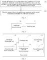
- a schematic structural diagram is as shown in FIG. 6 , and includes:
- a subframe determining unit 10 is configured to determine a first transmission subframe set R1 and a second transmission subframe set R2 of the user equipment within a predetermined time range, where the first transmission subframe set R1 is a set of a subframe on which the user equipment transmits uplink information, the second transmission subframe set R2 is a set of a subframe on which the user equipment directly transmits data to another user equipment, and intersection sets between the second transmission subframe set of the user equipment and a first transmission subframe set of another user equipment that directly communicates with the user equipment and between the second transmission subframe set of the user equipment and a second transmission subframe set of the another user equipment that directly communicates with the user equipment are empty.
- the predetermined time range may be a frame formed by multiple subframes or a super frame formed by multiple frames.
- the subframe determining unit 10 may further enable transmittable subframes included in the first transmission subframe set and the second transmission subframe set that are determined for each of the user equipments which directly communicate with each other to be consecutive within the predetermined time range, so that transmission subframes on which a user equipment sends data are consecutive, thereby reducing a switch point at which the user equipment performs state switching between sending data and receiving data.
- the subframe determining unit 10 reserves an idle subframe between sub frames included in second transmission subframe sets of any two user equipments which directly communicate with each other; or, the subframe determining unit 10 reserves a period of protection time in a subframe included in a second transmission subframe set of at least one user equipment of the user equipments which directly communicate with each other. In this way, the user equipment performs state switching between sending data and receiving data on the reserved idle subframe or in the reserved protection time.
- a notifying unit 11 is configured to notify information of the second transmission subframe set R2 determined by the subframe determining unit 10 to the user equipment, where the information of the second transmission subframe set R2 includes information such as the number of included subframes, a position of an included subframe and a usage state of the included subframe, and may further include information of the idle subframe or the protection time reserved by the subframe determining unit 10.
- the notifying unit 11 may notify information of a second transmission subframe set of any one of the user equipments which directly communicate with each other to a user equipment, and notify information of a second transmission subframe set of another user equipment that directly communicates with the user equipment to the user equipment. In this way, each user equipment may know a transmission subframe on which data is directly transmitted to another user equipment, and a transmission subframe on which data directly transmitted by the another user equipment is received.
- the notifying unit 11 may specifically use an information element newly added in dedicated signaling or common signaling of radio resource control to indicate the position of the subframe and/or the usage state of the subframe included in the second transmission subframe set, and send the dedicated signaling or the common signaling of the radio resource control to the user equipment; or, use a control element newly added in media access control layer signaling to indicate the position of the subframe and/or the usage state of the subframe included in the second transmission subframe set, and send the media access control layer signaling to the user equipment; or, use a control field newly added in signaling of a physical layer control channel to indicate the position of the subframe and/or the usage state of the subframe included in the second transmission subframe set, and send the signaling of the physical layer control channel to the user equipment.
- the new information element, or the new control element, or the new control field may further indicate: a configuration cycle of the second transmission subframe set used when the user equipment directly communicates with another user equipment; and, a configuration starting point of the second transmission subframe set used when the user equipment directly communicates with another user equipment. In this way, the user equipment may directly communicate with the another user equipment in the fixed configuration cycle according to the second transmission subframe set.
- the subframe determining unit 10 determines the first transmission subframe set for each of the user equipments which directly communicate with each other to transmit uplink information within the predetermined time range and the second transmission subframe set for each user equipment to directly transmit data to the another user equipment within the predetermined time range respectively, where intersection sets between a second transmission subframe set determined for any user equipment and a first transmission subframe set determined for another user equipment that directly communicates with the user equipment and between the second transmission subframe set determined for the any user equipment and a second transmission subframe set determined for the another user equipment that directly communicates with the user equipment are empty; and finally, the information of the determined second transmission subframe set is notified to the user equipment.
- the base station may further include a first adjusting unit 12, a second adjusting unit 13, a downlink subframe setting unit 14 and a retransmission interval determining unit 15.
- the first adjusting unit 12 is configured to: when a subframe subset R12 of the user equipment is not included in a union set of a subframe subset R11 and the second transmission subframe set R2 of the user equipment, adjust a subframe determined for the user equipment to transmit downlink data, so that the subset R12 of the subframe on which the user equipment transmits uplink response feedback information corresponding to the downlink data is included in the union set of the subframe subset R11 and the second transmission subframe set R2 of the user equipment.
- the uplink information transmitted by the user equipment includes uplink data information and uplink response feedback information, and accordingly, the first transmission subframe set R1 determined by the subframe determining unit 10 for the user equipment includes: a subset R11 of a subframe on which the user equipment transmits the uplink data information and a subset R12 of a subframe on which the user equipment transmits the uplink response feedback information.
- the second adjusting unit 13 is configured to: when a subframe subset R13 of the user equipment is not included in the union set of the subframe subset R11 and the second transmission subframe set R2 of the user equipment, adjust the subframe subset R13 of the user equipment, so that the subset R13 of the subframe on which the user equipment transmits channel state information is included in the union set of the subframe subset R11 and the second transmission subframe set R2 of the user equipment.
- the uplink information transmitted by the user equipment further includes the channel state information
- the first transmission subframe set determined by the subframe determining unit 10 for the user equipment further includes the subset R13 of the subframe on which the user equipment transmits the channel state information.
- the downlink subframe setting unit 14 is configured to set a transmission subframe for downlink retransmission data for the user equipment, so that a subframe on which the user equipment transmits uplink response feedback information corresponding to the downlink retransmission data is included in the subset R12 of the subframe for transmitting the uplink response feedback information.
- the retransmission interval determining unit 15 is configured to determine a retransmission interval at which the user equipment transmits the downlink retransmission data as a fixed value, so that a subframe on which the user equipment transmits uplink response feedback information corresponding to the downlink retransmission data is included in the subset R12 of the subframe on which the user equipment transmits the uplink response feedback information.
- the retransmission interval is the number of subframes between a moment of a subframe on which the user equipment transmits downlink data for the first time and a moment of a subframe on which the user equipment retransmits the downlink data for the first time; or, the retransmission interval is the number of subframes between a moment of a subframe on which the user equipment retransmits downlink data for the n th time and a moment of a subframe on which the user equipment retransmits the downlink data for the (n+1) th time, where n is a positive integer.
- the subframe determining unit 10 determines the first transmission subframe set and the second transmission subframe set for each user equipment
- the subset R12 of the subframe on which the user equipment transmits the uplink response feedback information corresponding to the downlink data may be included in the union set of the subframe subset R11 and the second transmission subframe set
- the subset R13 of the subframe on which the user equipment transmits the channel state information may be included in the union set of the subframe subset R11 and the second transmission subframe set.
- the downlink subframe setting unit 14 sets the transmission subframe on which the user equipment transmits the downlink data
- the retransmission interval determining unit 15 determines the retransmission interval at which the user equipment retransmits the downlink data as the fixed value
- the notifying unit 11 may further notify the user equipment of information such as information of the subframe set by the downlink subframe setting unit 14 and the retransmission interval determined by the retransmission interval determining unit 15.
- the subframe determining unit 10, the first adjusting unit 12, the second adjusting unit 13, the downlink subframe setting unit 14 and the retransmission interval determining unit 15 in the base station may all be included in a processor.
- the transmission subframe may be determined by the units of the base station shown in FIG. 6 and FIG. 7 according to the method described in the embodiment corresponding to FIG. 1 , which is not repeatedly described herein.
- An embodiment of the present invention further provides a user equipment.
- the user equipment may directly communicate with another user equipment.
- a schematic structural diagram is as shown in FIG. 8 , and includes:
- a subframe information acquiring unit 20 is configured to acquire information of a second transmission subframe set of the user equipment, where the second transmission subframe set is a set of a subframe on which the user equipment directly transmits data to another user equipment within a predetermined time range, and the information of the second transmission subframe set includes information such as a position of an included subframe, the number of included subframes and a usage state of the included subframe.
- the subframe information acquiring unit 20 may be configured to receive dedicated signaling or common signaling of radio resource control, and learn, according to an information element newly added in the dedicated signaling or the common signaling, the position of the subframe and/or the usage state of the subframe included in the second transmission subframe set of the user equipment.
- the subframe information acquiring unit 20 is further configured to receive media access control layer signaling, and learn, according to a control element newly added in the media access control layer signaling, the position of the subframe and/or the usage state of the subframe included in the second transmission subframe set of the user equipment.
- the subframe information acquiring unit 20 is further configured to receive signaling of a physical layer control channel, and learn, according to a control field newly added in the signaling of the physical layer control channel, the position of the subframe and/or the usage state of the subframe included in the second transmission subframe set of the user equipment.
- the subframe information acquiring unit 20 is further configured to acquire, according to the newly added information element, or the newly added control element, or the newly added control field, a configuration cycle of the second transmission subframe set used when the user equipment directly communicates with another user equipment; and a configuration starting point of the second transmission subframe set used when the user equipment directly communicates with another user equipment.
- a transmitting unit 21 is configured to directly transmit data to another user equipment on the second transmission subframe set which is of the current user equipment and corresponds to the information acquired by the subframe information acquiring unit 20.
- the subframe information acquiring unit 20 may further acquire information of a first transmission subframe set determined by the base station for the user equipment, including information such as a position of a subframe for transmitting uplink data information, uplink response feedback information or channel state information, and accordingly, the transmitting unit 21 is further configured to transmit the uplink information to the base station on the first transmission subframe set according to the information of the first transmission subframe set.
- the base station considers a factor that the user equipments directly communicate with each other, considers a factor that each user equipment communicates with the base station, determines respective second transmission subframe sets for the user equipments which directly communicate with each other, and sends information of the second transmission subframe set to the user equipment.
- the transmitting unit 21 directly transmits data to another user equipment on the second transmission subframe set of the user equipment.
- the user equipment may further include a receiving unit 22 and a state switching unit 23.
- the subframe information acquiring unit 20 is further configured to acquire information of a second transmission subframe set for the current user equipment to receive data directly transmitted by another user equipment, that is, information of the second transmission subframe set determined by the base station for the another user equipment.
- the receiving unit 22 is configured to receive, on the second transmission subframe set of the another user equipment and according to the information which is of the second transmission subframe set of the another user equipment and is acquired by the subframe information acquiring unit 20, the data directly transmitted by the another user equipment.
- the state switching unit 23 is configured to: if an idle subframe is reserved between the subframe included in the second transmission subframe set of the user equipment and the subframe included in the second transmission subframe set of the another user equipment, perform state switching on the reserved idle subframe between sending data and receiving data according to the information acquired by the subframe information acquiring unit 20.
- the state switching unit 23 is configured to: if a period of protection time is reserved in the subframe included in the second transmission subframe set of the user equipment, or in the subframe included in the second transmission subframe set of the another user equipment, perform state switching within the reserved protection time between sending data and receiving data according to the information acquired by the subframe information acquiring unit 20.
- An embodiment of the present invention further provides a system for determining a transmission subframe, where the system is used to determine a transmission subframe for data transmission between multiple user equipments which directly communicate with each other, and includes a base station and at least two user equipments which directly communicate with each other.
- the base station is configured to determine a first transmission subframe set and a second transmission subframe set of the user equipment within a predetermined time range, where the first transmission subframe set is a set of a subframe on which the user equipment transmits uplink information, the second transmission subframe set is a set of a subframe on which the user equipment directly transmits data to another user equipment, and intersection sets between the second transmission subframe set of the user equipment and a first transmission subframe set of another user equipment that directly communicates with the user equipment and between the second transmission subframe set of the user equipment and a second transmission subframe set of the another user equipment that directly communicates with the user equipment are empty; and notify information of the determined second transmission subframe set to the user equipment.
- the user equipment is configured to acquire the information of the second transmission subframe set of the user equipment, and directly transmit data to the another user equipment on the second transmission subframe set of the user equipment.
- a structure of the base station in this embodiment may be as shown in FIG. 6 or FIG. 7
- a structure of the user equipment may be as shown in FIG. 8 or FIG. 9 , which are not repeatedly described herein.
- the program may be stored in a computer readable storage medium.
- the storage medium may include a read only memory (ROM), a random access memory (RAM), a magnetic disk, or an optical disk, or the like.
Landscapes
- Engineering & Computer Science (AREA)
- Computer Networks & Wireless Communication (AREA)
- Signal Processing (AREA)
- Quality & Reliability (AREA)
- Mobile Radio Communication Systems (AREA)
Claims (5)
- Procédé permettant de déterminer une sous-trame de transmission, utilisé pour déterminer une sous-trame de transmission pour une transmission de données entre plusieurs équipements utilisateur qui communiquent directement entre eux, et comprenant les étapes suivantes :déterminer (101) un premier ensemble de sous-trame de transmission et un deuxième ensemble de sous-trame de transmission d'un équipement utilisateur à l'intérieur d'une plage de temps prédéterminée, le premier ensemble de sous-trame de transmission étant un ensemble d'une sous-trame sur laquelle l'équipement utilisateur transmet des informations de liaison montante, le deuxième ensemble de sous-trame de transmission étant un ensemble d'une sous-trame sur laquelle l'équipement utilisateur transmet directement des données à un autre équipement utilisateur, et des ensembles d'intersections, qui sont vides entre le deuxième ensemble de sous-trame de transmission de l'équipement utilisateur et un premier ensemble de sous-trame de transmission d'un autre équipement utilisateur qui communique directement avec l'équipement utilisateur et entre le deuxième ensemble de sous-trame de transmission de l'équipement utilisateur et un deuxième ensemble de sous-trame de transmission de l'autre équipement utilisateur qui communique directement avec l'équipement utilisateur ; etnotifier (102) des informations du deuxième ensemble de sous-trame de transmission de l'équipement utilisateur à l'équipement utilisateur,les informations de liaison montante comportant des informations de données de liaison montante et des informations de rétroaction de réponse de liaison montante ;le premier ensemble de sous-trame de transmission de l'équipement utilisateur comprenant: un sous-ensemble R11 d'une sous-trame sur laquelle l'équipement utilisateur transmet les informations de données de liaison montante et un sous-ensemble R12 d'une sous-trame sur laquelle l'équipement utilisateur transmet les informations de rétroaction de réponse de liaison montante ; etcaractérisé par l'étape consistant àdéterminer si le sous-ensemble de sous-trame R12 n'est pas compris dans un ensemble d'union du sous-ensemble de sous-trame R11 et du deuxième ensemble de sous-trame de transmission de l'équipement utilisateur, et, si tel est le cas, le procédé comprenant en outre : ajuster une sous-trame déterminée pour l'équipement utilisateur pour transmettre des données de liaison descendante, afin que le sous-ensemble R12 de la sous-trame sur laquelle l'équipement utilisateur transmet des informations de rétroaction de réponse de liaison montante correspondant aux données de liaison descendante soit compris dans l'ensemble d'union du sous-ensemble de sous-trame R11 et du deuxième ensemble de sous-trame de transmission de l'équipement utilisateur.
- Procédé selon la revendication 1, dans lequel les informations de liaison montante transmises comprennent en outre des informations d'état de canal, et en conséquence, le premier ensemble de sous-trame de transmission de l'équipement utilisateur comprend en outre : un sous-ensemble R13 d'une sous-trame sur laquelle l'équipement utilisateur transmet les informations d'état de canal ; et
si le sous-ensemble de sous-trame R13 n'est pas compris dans l'ensemble d'union du sous-ensemble de sous-trame R11 et du deuxième ensemble de sous-trame de transmission de l'équipement utilisateur, le procédé comprend en outre : ajuster le sous-ensemble de sous-trame R13, afin que le sous-ensemble de sous-trame R13 soit compris dans l'ensemble d'union du sous-ensemble de sous-trame R11 et du deuxième ensemble de sous-trame de transmission de l'équipement utilisateur. - Station de base, configurée pour déterminer une sous-trame de transmission pour une transmission de données entre plusieurs équipements utilisateur qui communiquent directement entre eux, et comprenant :une unité de détermination de sous-trame (10), configurée pour déterminer un premier ensemble de sous-trame de transmission et un deuxième ensemble de sous-trame de transmission de l'équipement utilisateur à l'intérieur d'une plage de temps prédéterminée, le premier ensemble de sous-trame de transmission étant un ensemble d'une sous-trame sur laquelle l'équipement utilisateur transmet des informations de liaison montante, le deuxième ensemble de sous-trame de transmission étant un ensemble d'une sous-trame sur laquelle l'équipement utilisateur transmet directement des données à un autre équipement utilisateur, et des ensembles d'intersections, qui sont vides, entre le deuxième ensemble de sous-trame de transmission de l'équipement utilisateur et un premier ensemble de sous-trame de transmission d'un autre équipement utilisateur qui communique directement avec l'équipement utilisateur et entre le deuxième ensemble de sous-trame de transmission de l'équipement utilisateur et un deuxième ensemble de sous-trame de transmission de l'autre équipement utilisateur qui communique directement avec l'équipement utilisateur ; etune unité de notification (11), configurée pour notifier des informations du deuxième ensemble de sous-trame de transmission déterminé par l'unité de détermination de sous-trame à l'équipement utilisateur,les informations de liaison montante comportant des informations de données de liaison montante et des informations de rétroaction de réponse de liaison montante ;et le premier ensemble de sous-trame de transmission déterminé par l'unité de détermination de sous-trame pour l'équipement utilisateur comprenant : un sous-ensemble R11 d'une sous-trame sur laquelle l'équipement utilisateur transmet les informations de données de liaison montante et un sous-ensemble R12 d'une sous-trame sur laquelle l'équipement utilisateur transmet les informations de rétroaction de réponse de liaison montante ; etla station de base étant caractérisée en outre par :une première unité d'ajustement (12), configurée pour : lorsqu'il est déterminé que le sous-ensemble de sous-trame R12 de l'équipement utilisateur n'est pas compris dans un ensemble d'union du sous-ensemble de sous-trame R11 et du deuxième ensemble de sous-trame de transmission de l'équipement utilisateur, ajuster une sous-trame déterminée pour l'équipement utilisateur pour transmettre des données de liaison descendante, afin que le sous-ensemble R12 de la sous-trame sur laquelle l'équipement utilisateur transmet des informations de rétroaction de réponse de liaison montante correspondant aux données de liaison descendante soit compris dans l'ensemble d'union du sous-ensemble de sous-trame R11 et du deuxième ensemble de sous-trame de transmission de l'équipement utilisateur.
- Station de base selon la revendication 3, dans laquelle :l'unité de notification (11) est configurée pour utiliser un élément d'informations nouvellement ajouté dans une signalisation dédiée ou dans une signalisation commune de contrôle de ressources radio pour indiquer les informations du deuxième ensemble de sous-trame de transmission, et envoyer la signalisation dédiée ou la signalisation commune du contrôle de ressource radio à l'équipement utilisateur ;ou, utiliser un élément de commande nouvellement ajouté dans une signalisation de couche de contrôle d'accès au support pour indiquer les informations du deuxième ensemble de sous-trame de transmission, et envoyer la signalisation de couche de contrôle d'accès au support à l'équipement utilisateur ;ou, utiliser un champ de commande nouvellement ajouté dans la signalisation d'un canal de contrôle de couche physique pour indiquer les informations du deuxième ensemble de sous-trame de transmission, et envoyer la signalisation du canal de contrôle de couche physique à l'équipement utilisateur ;les informations du deuxième ensemble de sous-trame de transmission de l'équipement utilisateur comprenant : une position d'une sous-trame et/ou un état d'utilisation d'une sous-trame.
- Système permettant de déterminer une sous-trame de transmission, utilisé pour déterminer une sous-trame de transmission pour une transmission de données entre plusieurs équipements utilisateur qui communiquent directement entre eux, et comprenant une station de base et au moins deux équipements utilisateur qui communiquent directement entre eux,
la station de base étant selon la revendication 3 ou la revendication 4.
Applications Claiming Priority (2)
| Application Number | Priority Date | Filing Date | Title |
|---|---|---|---|
| CN201210018163.3A CN103220782B (zh) | 2012-01-19 | 2012-01-19 | 一种传输子帧的确定方法、系统及设备 |
| PCT/CN2013/070761 WO2013107407A1 (fr) | 2012-01-19 | 2013-01-21 | Procédé, système et dispositif de détermination de sous-trames de transmission |
Publications (3)
| Publication Number | Publication Date |
|---|---|
| EP2797373A1 EP2797373A1 (fr) | 2014-10-29 |
| EP2797373A4 EP2797373A4 (fr) | 2014-11-26 |
| EP2797373B1 true EP2797373B1 (fr) | 2016-10-26 |
Family
ID=48798663
Family Applications (1)
| Application Number | Title | Priority Date | Filing Date |
|---|---|---|---|
| EP13739055.5A Active EP2797373B1 (fr) | 2012-01-19 | 2013-01-21 | Procédé, système et dispositif de détermination de sous-trames de transmission |
Country Status (4)
| Country | Link |
|---|---|
| US (1) | US9468002B2 (fr) |
| EP (1) | EP2797373B1 (fr) |
| CN (1) | CN103220782B (fr) |
| WO (1) | WO2013107407A1 (fr) |
Families Citing this family (9)
| Publication number | Priority date | Publication date | Assignee | Title |
|---|---|---|---|---|
| CN104349470B (zh) | 2013-08-02 | 2018-11-30 | 华为终端有限公司 | 一种发送信息方法和装置 |
| CN103944701B (zh) * | 2013-08-26 | 2017-08-08 | 上海朗帛通信技术有限公司 | 一种tdd‑fdd联合系统中的传输方法和装置 |
| CN105516886B (zh) * | 2014-09-25 | 2019-08-23 | 上海诺基亚贝尔股份有限公司 | 用于d2d通信的方法和设备 |
| CN107231687B (zh) * | 2016-03-24 | 2020-01-14 | 上海朗帛通信技术有限公司 | 一种蜂窝网的窄带通信的方法和装置 |
| US11272512B2 (en) * | 2017-01-06 | 2022-03-08 | Sony Corporation | Wireless telecommunications apparatuses and methods |
| CN109451870B (zh) * | 2018-05-18 | 2023-10-10 | 北京小米移动软件有限公司 | 上行数据传输方法、装置及计算机可读存储介质 |
| WO2020034429A1 (fr) * | 2018-11-02 | 2020-02-20 | Zte Corporation | Procédés, appareils et systèmes d'indication de ressources de transmission de liaison montante relatives à divers services |
| CN113973283B (zh) * | 2020-07-23 | 2025-05-13 | 夏普株式会社 | 由用户设备执行的方法以及用户设备 |
| CN111918341B (zh) | 2020-08-03 | 2025-07-25 | 中兴通讯股份有限公司 | 符号预留、询问、通知方法、第一节点、第二节点及介质 |
Family Cites Families (8)
| Publication number | Priority date | Publication date | Assignee | Title |
|---|---|---|---|---|
| US5515366A (en) * | 1994-11-17 | 1996-05-07 | International Business Machines Corporation | Method and apparatus for direct communication in a TDMA radio communication system |
| CN1312955C (zh) * | 2000-12-11 | 2007-04-25 | 夏普株式会社 | 无线通信系统 |
| US7760694B2 (en) * | 2006-07-19 | 2010-07-20 | Intel Corporation | Deviating from a transmission map to communicate in a wireless network |
| CN100591163C (zh) * | 2006-10-09 | 2010-02-17 | 北京信威通信技术股份有限公司 | 一种实现scdma系统终端与终端直接通信的方法及其应用 |
| CN102282901B (zh) * | 2009-01-16 | 2015-06-17 | 诺基亚公司 | 在蜂窝网络中实现装置到装置通信 |
| CN105025592A (zh) * | 2009-09-18 | 2015-11-04 | 交互数字专利控股公司 | 一种在sta中使用的方法及sta |
| WO2013025158A1 (fr) * | 2011-08-12 | 2013-02-21 | Telefonaktiebolaget Lm Ericsson (Publ) | Procédés et nœuds pour coordonner des transmissions sur la liaison montante dans un réseau de communication sans fil |
| CN102307060B (zh) * | 2011-08-31 | 2015-08-19 | 电信科学技术研究院 | 一种传输数据的方法和设备 |
-
2012
- 2012-01-19 CN CN201210018163.3A patent/CN103220782B/zh active Active
-
2013
- 2013-01-21 EP EP13739055.5A patent/EP2797373B1/fr active Active
- 2013-01-21 WO PCT/CN2013/070761 patent/WO2013107407A1/fr not_active Ceased
-
2014
- 2014-07-18 US US14/335,557 patent/US9468002B2/en active Active
Also Published As
| Publication number | Publication date |
|---|---|
| US20140348088A1 (en) | 2014-11-27 |
| CN103220782A (zh) | 2013-07-24 |
| US9468002B2 (en) | 2016-10-11 |
| CN103220782B (zh) | 2017-08-18 |
| WO2013107407A1 (fr) | 2013-07-25 |
| EP2797373A1 (fr) | 2014-10-29 |
| EP2797373A4 (fr) | 2014-11-26 |
Similar Documents
| Publication | Publication Date | Title |
|---|---|---|
| EP2797373B1 (fr) | Procédé, système et dispositif de détermination de sous-trames de transmission | |
| JP6956065B2 (ja) | 無線ネットワークにおけるアップリンク制御情報送/受信 | |
| CN111213416B (zh) | 无线网络中上行链路控制信令资源的动态管理 | |
| KR102517317B1 (ko) | V2x 통신에서 송신 자원을 결정하는 방법 및 장치 | |
| US11032778B2 (en) | Uplink channel power allocation method and apparatus | |
| CN111654917B (zh) | 用于免授权上行链路传输方案的传输系统和方法 | |
| JP6082121B2 (ja) | 情報送信方法、ユーザ装置及び基地局 | |
| US9414427B2 (en) | Link adaptation transmission and reception method in device-to-device communication based cellular mobile communication system | |
| CN108184268B (zh) | 一种业务适配的普适帧结构配置方法 | |
| KR20180092978A (ko) | 분산된 비스케줄링된 송신들을 위한 네트워크 지원 | |
| EP2858436B1 (fr) | Procédé et dispositif de programmation de transmission de données en liaison descendante | |
| US20140307662A1 (en) | Method and apparatus for processing receive/transmit transition time of user equipment | |
| CN103199969B (zh) | 处理混合式自动重发请求确认收讫响应的方法及通讯装置 | |
| EP3255928A1 (fr) | Procédé d'accès aléatoire, équipement utilisateur et station de base | |
| CN108271251A (zh) | 一种上行控制的资源确定方法、装置、发送端和接收端 | |
| EP2613470B1 (fr) | Procédé de gestion de ressources de demande de répétition automatique hybride dans un système de communication sans fil | |
| CN105991209A (zh) | 一种增强的ca中的pucch方法和装置 | |
| KR20190100042A (ko) | 통신 시스템에서 bwp 운용을 위한 방법 및 장치 | |
| EP4037423A1 (fr) | Procédé et dispositif de traitement d'opération de liaison latérale, et support de stockage | |
| JP2021516925A (ja) | 無線リソーススケジューリング | |
| CN103475456A (zh) | 处理混合式自动重送请求的方法及其通信装置 | |
| CN105245316A (zh) | 一种传输上行控制信令的方法、系统和设备 | |
| CN103475457A (zh) | 处理混合式自动重送请求资源的方法及其通信装置 | |
| US20260040315A1 (en) | Methods and apparatuses of an enhanced transmission on a preconfigured resource | |
| CN118044301A (zh) | 被取消的harq-ack反馈的重传方法、harq-ack反馈的pucch载波切换的方法及相关设备 |
Legal Events
| Date | Code | Title | Description |
|---|---|---|---|
| PUAI | Public reference made under article 153(3) epc to a published international application that has entered the european phase |
Free format text: ORIGINAL CODE: 0009012 |
|
| 17P | Request for examination filed |
Effective date: 20140721 |
|
| AK | Designated contracting states |
Kind code of ref document: A1 Designated state(s): AL AT BE BG CH CY CZ DE DK EE ES FI FR GB GR HR HU IE IS IT LI LT LU LV MC MK MT NL NO PL PT RO RS SE SI SK SM TR |
|
| A4 | Supplementary search report drawn up and despatched |
Effective date: 20141023 |
|
| RIC1 | Information provided on ipc code assigned before grant |
Ipc: H04W 76/02 20090101ALN20141017BHEP Ipc: H04W 72/04 20090101AFI20141017BHEP |
|
| DAX | Request for extension of the european patent (deleted) | ||
| 17Q | First examination report despatched |
Effective date: 20150814 |
|
| GRAP | Despatch of communication of intention to grant a patent |
Free format text: ORIGINAL CODE: EPIDOSNIGR1 |
|
| RIC1 | Information provided on ipc code assigned before grant |
Ipc: H04W 76/02 20090101ALN20160412BHEP Ipc: H04W 72/04 20090101AFI20160412BHEP Ipc: H04L 1/00 20060101ALI20160412BHEP |
|
| INTG | Intention to grant announced |
Effective date: 20160502 |
|
| GRAS | Grant fee paid |
Free format text: ORIGINAL CODE: EPIDOSNIGR3 |
|
| GRAA | (expected) grant |
Free format text: ORIGINAL CODE: 0009210 |
|
| AK | Designated contracting states |
Kind code of ref document: B1 Designated state(s): AL AT BE BG CH CY CZ DE DK EE ES FI FR GB GR HR HU IE IS IT LI LT LU LV MC MK MT NL NO PL PT RO RS SE SI SK SM TR |
|
| REG | Reference to a national code |
Ref country code: GB Ref legal event code: FG4D |
|
| REG | Reference to a national code |
Ref country code: CH Ref legal event code: EP |
|
| REG | Reference to a national code |
Ref country code: AT Ref legal event code: REF Ref document number: 840789 Country of ref document: AT Kind code of ref document: T Effective date: 20161115 |
|
| REG | Reference to a national code |
Ref country code: IE Ref legal event code: FG4D |
|
| REG | Reference to a national code |
Ref country code: DE Ref legal event code: R096 Ref document number: 602013013230 Country of ref document: DE |
|
| REG | Reference to a national code |
Ref country code: LT Ref legal event code: MG4D |
|
| PG25 | Lapsed in a contracting state [announced via postgrant information from national office to epo] |
Ref country code: LV Free format text: LAPSE BECAUSE OF FAILURE TO SUBMIT A TRANSLATION OF THE DESCRIPTION OR TO PAY THE FEE WITHIN THE PRESCRIBED TIME-LIMIT Effective date: 20161026 |
|
| REG | Reference to a national code |
Ref country code: NL Ref legal event code: MP Effective date: 20161026 |
|
| REG | Reference to a national code |
Ref country code: AT Ref legal event code: MK05 Ref document number: 840789 Country of ref document: AT Kind code of ref document: T Effective date: 20161026 |
|
| PG25 | Lapsed in a contracting state [announced via postgrant information from national office to epo] |
Ref country code: GR Free format text: LAPSE BECAUSE OF FAILURE TO SUBMIT A TRANSLATION OF THE DESCRIPTION OR TO PAY THE FEE WITHIN THE PRESCRIBED TIME-LIMIT Effective date: 20170127 Ref country code: SE Free format text: LAPSE BECAUSE OF FAILURE TO SUBMIT A TRANSLATION OF THE DESCRIPTION OR TO PAY THE FEE WITHIN THE PRESCRIBED TIME-LIMIT Effective date: 20161026 Ref country code: LT Free format text: LAPSE BECAUSE OF FAILURE TO SUBMIT A TRANSLATION OF THE DESCRIPTION OR TO PAY THE FEE WITHIN THE PRESCRIBED TIME-LIMIT Effective date: 20161026 Ref country code: NO Free format text: LAPSE BECAUSE OF FAILURE TO SUBMIT A TRANSLATION OF THE DESCRIPTION OR TO PAY THE FEE WITHIN THE PRESCRIBED TIME-LIMIT Effective date: 20170126 |
|
| PG25 | Lapsed in a contracting state [announced via postgrant information from national office to epo] |
Ref country code: FI Free format text: LAPSE BECAUSE OF FAILURE TO SUBMIT A TRANSLATION OF THE DESCRIPTION OR TO PAY THE FEE WITHIN THE PRESCRIBED TIME-LIMIT Effective date: 20161026 Ref country code: IS Free format text: LAPSE BECAUSE OF FAILURE TO SUBMIT A TRANSLATION OF THE DESCRIPTION OR TO PAY THE FEE WITHIN THE PRESCRIBED TIME-LIMIT Effective date: 20170226 Ref country code: AT Free format text: LAPSE BECAUSE OF FAILURE TO SUBMIT A TRANSLATION OF THE DESCRIPTION OR TO PAY THE FEE WITHIN THE PRESCRIBED TIME-LIMIT Effective date: 20161026 Ref country code: HR Free format text: LAPSE BECAUSE OF FAILURE TO SUBMIT A TRANSLATION OF THE DESCRIPTION OR TO PAY THE FEE WITHIN THE PRESCRIBED TIME-LIMIT Effective date: 20161026 Ref country code: PL Free format text: LAPSE BECAUSE OF FAILURE TO SUBMIT A TRANSLATION OF THE DESCRIPTION OR TO PAY THE FEE WITHIN THE PRESCRIBED TIME-LIMIT Effective date: 20161026 Ref country code: PT Free format text: LAPSE BECAUSE OF FAILURE TO SUBMIT A TRANSLATION OF THE DESCRIPTION OR TO PAY THE FEE WITHIN THE PRESCRIBED TIME-LIMIT Effective date: 20170227 Ref country code: NL Free format text: LAPSE BECAUSE OF FAILURE TO SUBMIT A TRANSLATION OF THE DESCRIPTION OR TO PAY THE FEE WITHIN THE PRESCRIBED TIME-LIMIT Effective date: 20161026 Ref country code: RS Free format text: LAPSE BECAUSE OF FAILURE TO SUBMIT A TRANSLATION OF THE DESCRIPTION OR TO PAY THE FEE WITHIN THE PRESCRIBED TIME-LIMIT Effective date: 20161026 Ref country code: ES Free format text: LAPSE BECAUSE OF FAILURE TO SUBMIT A TRANSLATION OF THE DESCRIPTION OR TO PAY THE FEE WITHIN THE PRESCRIBED TIME-LIMIT Effective date: 20161026 Ref country code: BE Free format text: LAPSE BECAUSE OF FAILURE TO SUBMIT A TRANSLATION OF THE DESCRIPTION OR TO PAY THE FEE WITHIN THE PRESCRIBED TIME-LIMIT Effective date: 20161026 |
|
| REG | Reference to a national code |
Ref country code: DE Ref legal event code: R097 Ref document number: 602013013230 Country of ref document: DE |
|
| PG25 | Lapsed in a contracting state [announced via postgrant information from national office to epo] |
Ref country code: RO Free format text: LAPSE BECAUSE OF FAILURE TO SUBMIT A TRANSLATION OF THE DESCRIPTION OR TO PAY THE FEE WITHIN THE PRESCRIBED TIME-LIMIT Effective date: 20161026 Ref country code: DK Free format text: LAPSE BECAUSE OF FAILURE TO SUBMIT A TRANSLATION OF THE DESCRIPTION OR TO PAY THE FEE WITHIN THE PRESCRIBED TIME-LIMIT Effective date: 20161026 Ref country code: EE Free format text: LAPSE BECAUSE OF FAILURE TO SUBMIT A TRANSLATION OF THE DESCRIPTION OR TO PAY THE FEE WITHIN THE PRESCRIBED TIME-LIMIT Effective date: 20161026 Ref country code: SK Free format text: LAPSE BECAUSE OF FAILURE TO SUBMIT A TRANSLATION OF THE DESCRIPTION OR TO PAY THE FEE WITHIN THE PRESCRIBED TIME-LIMIT Effective date: 20161026 Ref country code: CZ Free format text: LAPSE BECAUSE OF FAILURE TO SUBMIT A TRANSLATION OF THE DESCRIPTION OR TO PAY THE FEE WITHIN THE PRESCRIBED TIME-LIMIT Effective date: 20161026 |
|
| PG25 | Lapsed in a contracting state [announced via postgrant information from national office to epo] |
Ref country code: SM Free format text: LAPSE BECAUSE OF FAILURE TO SUBMIT A TRANSLATION OF THE DESCRIPTION OR TO PAY THE FEE WITHIN THE PRESCRIBED TIME-LIMIT Effective date: 20161026 Ref country code: BG Free format text: LAPSE BECAUSE OF FAILURE TO SUBMIT A TRANSLATION OF THE DESCRIPTION OR TO PAY THE FEE WITHIN THE PRESCRIBED TIME-LIMIT Effective date: 20170126 |
|
| REG | Reference to a national code |
Ref country code: CH Ref legal event code: PL |
|
| PLBE | No opposition filed within time limit |
Free format text: ORIGINAL CODE: 0009261 |
|
| STAA | Information on the status of an ep patent application or granted ep patent |
Free format text: STATUS: NO OPPOSITION FILED WITHIN TIME LIMIT |
|
| PG25 | Lapsed in a contracting state [announced via postgrant information from national office to epo] |
Ref country code: MC Free format text: LAPSE BECAUSE OF FAILURE TO SUBMIT A TRANSLATION OF THE DESCRIPTION OR TO PAY THE FEE WITHIN THE PRESCRIBED TIME-LIMIT Effective date: 20161026 |
|
| 26N | No opposition filed |
Effective date: 20170727 |
|
| REG | Reference to a national code |
Ref country code: FR Ref legal event code: ST Effective date: 20170929 |
|
| PG25 | Lapsed in a contracting state [announced via postgrant information from national office to epo] |
Ref country code: CH Free format text: LAPSE BECAUSE OF NON-PAYMENT OF DUE FEES Effective date: 20170131 Ref country code: FR Free format text: LAPSE BECAUSE OF NON-PAYMENT OF DUE FEES Effective date: 20170131 Ref country code: LI Free format text: LAPSE BECAUSE OF NON-PAYMENT OF DUE FEES Effective date: 20170131 |
|
| REG | Reference to a national code |
Ref country code: IE Ref legal event code: MM4A |
|
| PG25 | Lapsed in a contracting state [announced via postgrant information from national office to epo] |
Ref country code: LU Free format text: LAPSE BECAUSE OF NON-PAYMENT OF DUE FEES Effective date: 20170121 Ref country code: SI Free format text: LAPSE BECAUSE OF FAILURE TO SUBMIT A TRANSLATION OF THE DESCRIPTION OR TO PAY THE FEE WITHIN THE PRESCRIBED TIME-LIMIT Effective date: 20161026 |
|
| PG25 | Lapsed in a contracting state [announced via postgrant information from national office to epo] |
Ref country code: IE Free format text: LAPSE BECAUSE OF NON-PAYMENT OF DUE FEES Effective date: 20170121 |
|
| PG25 | Lapsed in a contracting state [announced via postgrant information from national office to epo] |
Ref country code: MT Free format text: LAPSE BECAUSE OF NON-PAYMENT OF DUE FEES Effective date: 20170121 |
|
| PG25 | Lapsed in a contracting state [announced via postgrant information from national office to epo] |
Ref country code: HU Free format text: LAPSE BECAUSE OF FAILURE TO SUBMIT A TRANSLATION OF THE DESCRIPTION OR TO PAY THE FEE WITHIN THE PRESCRIBED TIME-LIMIT; INVALID AB INITIO Effective date: 20130121 |
|
| PG25 | Lapsed in a contracting state [announced via postgrant information from national office to epo] |
Ref country code: CY Free format text: LAPSE BECAUSE OF FAILURE TO SUBMIT A TRANSLATION OF THE DESCRIPTION OR TO PAY THE FEE WITHIN THE PRESCRIBED TIME-LIMIT Effective date: 20161026 |
|
| PG25 | Lapsed in a contracting state [announced via postgrant information from national office to epo] |
Ref country code: MK Free format text: LAPSE BECAUSE OF FAILURE TO SUBMIT A TRANSLATION OF THE DESCRIPTION OR TO PAY THE FEE WITHIN THE PRESCRIBED TIME-LIMIT Effective date: 20161026 |
|
| PG25 | Lapsed in a contracting state [announced via postgrant information from national office to epo] |
Ref country code: TR Free format text: LAPSE BECAUSE OF FAILURE TO SUBMIT A TRANSLATION OF THE DESCRIPTION OR TO PAY THE FEE WITHIN THE PRESCRIBED TIME-LIMIT Effective date: 20161026 |
|
| PG25 | Lapsed in a contracting state [announced via postgrant information from national office to epo] |
Ref country code: AL Free format text: LAPSE BECAUSE OF FAILURE TO SUBMIT A TRANSLATION OF THE DESCRIPTION OR TO PAY THE FEE WITHIN THE PRESCRIBED TIME-LIMIT Effective date: 20161026 |
|
| PGFP | Annual fee paid to national office [announced via postgrant information from national office to epo] |
Ref country code: GB Payment date: 20251204 Year of fee payment: 14 |
|
| PGFP | Annual fee paid to national office [announced via postgrant information from national office to epo] |
Ref country code: DE Payment date: 20251203 Year of fee payment: 14 |
|
| PGFP | Annual fee paid to national office [announced via postgrant information from national office to epo] |
Ref country code: IT Payment date: 20251219 Year of fee payment: 14 |