EP2797752B1 - Découpe de supports - Google Patents
Découpe de supports Download PDFInfo
- Publication number
- EP2797752B1 EP2797752B1 EP11878887.6A EP11878887A EP2797752B1 EP 2797752 B1 EP2797752 B1 EP 2797752B1 EP 11878887 A EP11878887 A EP 11878887A EP 2797752 B1 EP2797752 B1 EP 2797752B1
- Authority
- EP
- European Patent Office
- Prior art keywords
- media
- printer
- printing
- cutter assembly
- control circuit
- Prior art date
- Legal status (The legal status is an assumption and is not a legal conclusion. Google has not performed a legal analysis and makes no representation as to the accuracy of the status listed.)
- Active
Links
Images


Classifications
-
- B—PERFORMING OPERATIONS; TRANSPORTING
- B41—PRINTING; LINING MACHINES; TYPEWRITERS; STAMPS
- B41J—TYPEWRITERS; SELECTIVE PRINTING MECHANISMS, i.e. MECHANISMS PRINTING OTHERWISE THAN FROM A FORME; CORRECTION OF TYPOGRAPHICAL ERRORS
- B41J11/00—Devices or arrangements of selective printing mechanisms, e.g. ink-jet printers or thermal printers, for supporting or handling copy material in sheet or web form
- B41J11/66—Applications of cutting devices
- B41J11/663—Controlling cutting, cutting resulting in special shapes of the cutting line, e.g. controlling cutting positions, e.g. for cutting in the immediate vicinity of a printed image
-
- B—PERFORMING OPERATIONS; TRANSPORTING
- B41—PRINTING; LINING MACHINES; TYPEWRITERS; STAMPS
- B41J—TYPEWRITERS; SELECTIVE PRINTING MECHANISMS, i.e. MECHANISMS PRINTING OTHERWISE THAN FROM A FORME; CORRECTION OF TYPOGRAPHICAL ERRORS
- B41J11/00—Devices or arrangements of selective printing mechanisms, e.g. ink-jet printers or thermal printers, for supporting or handling copy material in sheet or web form
- B41J11/36—Blanking or long feeds; Feeding to a particular line, e.g. by rotation of platen or feed roller
- B41J11/42—Controlling printing material conveyance for accurate alignment of the printing material with the printhead; Print registering
- B41J11/425—Controlling printing material conveyance for accurate alignment of the printing material with the printhead; Print registering for a variable printing material feed amount
-
- B—PERFORMING OPERATIONS; TRANSPORTING
- B41—PRINTING; LINING MACHINES; TYPEWRITERS; STAMPS
- B41J—TYPEWRITERS; SELECTIVE PRINTING MECHANISMS, i.e. MECHANISMS PRINTING OTHERWISE THAN FROM A FORME; CORRECTION OF TYPOGRAPHICAL ERRORS
- B41J11/00—Devices or arrangements of selective printing mechanisms, e.g. ink-jet printers or thermal printers, for supporting or handling copy material in sheet or web form
- B41J11/66—Applications of cutting devices
- B41J11/70—Applications of cutting devices cutting perpendicular to the direction of paper feed
- B41J11/706—Applications of cutting devices cutting perpendicular to the direction of paper feed using a cutting tool mounted on a reciprocating carrier
-
- G—PHYSICS
- G06—COMPUTING OR CALCULATING; COUNTING
- G06K—GRAPHICAL DATA READING; PRESENTATION OF DATA; RECORD CARRIERS; HANDLING RECORD CARRIERS
- G06K15/00—Arrangements for producing a permanent visual presentation of the output data, e.g. computer output printers
- G06K15/02—Arrangements for producing a permanent visual presentation of the output data, e.g. computer output printers using printers
- G06K15/10—Arrangements for producing a permanent visual presentation of the output data, e.g. computer output printers using printers by matrix printers
- G06K15/102—Arrangements for producing a permanent visual presentation of the output data, e.g. computer output printers using printers by matrix printers using ink jet print heads
- G06K15/105—Multipass or interlaced printing
-
- G—PHYSICS
- G06—COMPUTING OR CALCULATING; COUNTING
- G06K—GRAPHICAL DATA READING; PRESENTATION OF DATA; RECORD CARRIERS; HANDLING RECORD CARRIERS
- G06K15/00—Arrangements for producing a permanent visual presentation of the output data, e.g. computer output printers
- G06K15/02—Arrangements for producing a permanent visual presentation of the output data, e.g. computer output printers using printers
- G06K15/10—Arrangements for producing a permanent visual presentation of the output data, e.g. computer output printers using printers by matrix printers
- G06K15/102—Arrangements for producing a permanent visual presentation of the output data, e.g. computer output printers using printers by matrix printers using ink jet print heads
- G06K15/105—Multipass or interlaced printing
- G06K15/107—Mask selection
-
- G—PHYSICS
- G06—COMPUTING OR CALCULATING; COUNTING
- G06K—GRAPHICAL DATA READING; PRESENTATION OF DATA; RECORD CARRIERS; HANDLING RECORD CARRIERS
- G06K2215/00—Arrangements for producing a permanent visual presentation of the output data
- G06K2215/111—Arrangements for producing a permanent visual presentation of the output data with overlapping swaths
-
- Y—GENERAL TAGGING OF NEW TECHNOLOGICAL DEVELOPMENTS; GENERAL TAGGING OF CROSS-SECTIONAL TECHNOLOGIES SPANNING OVER SEVERAL SECTIONS OF THE IPC; TECHNICAL SUBJECTS COVERED BY FORMER USPC CROSS-REFERENCE ART COLLECTIONS [XRACs] AND DIGESTS
- Y10—TECHNICAL SUBJECTS COVERED BY FORMER USPC
- Y10T—TECHNICAL SUBJECTS COVERED BY FORMER US CLASSIFICATION
- Y10T83/00—Cutting
- Y10T83/283—With means to control or modify temperature of apparatus or work
Definitions
- a media roll When printing on a media roll, at some point the printed media portion needs to be separated from the rest of the roll.
- Media rolls or other media types may be cut by a cutter device that is separate from the printer.
- a cutter device is integrated with or attached to a printer already.
- a media roll needs to be positioned for cutting after printing a first media portion, and then repositioned for printing a second media portion.
- Cutting media including positioning and repositioning, may provide for a substantial delay of the printing process.
- US 2002/067943 discloses a tape printing apparatus with a full-cutting device and a half-cutting device arranged at a location downstream of the printing section in a tape-feeding direction, for cutting off the tape material.
- a control section individually and separately controls the tape feeding section, the printing section, the full-cutting device, and the half-cutting device.
- US 2008/181711 discloses a cutter assembly for cutting printed media in a printer.
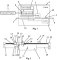
- Fig. 1 shows an example of a printer 1.
- the printer 1 includes a printhead assembly 2 and a cutter assembly 3 arranged downstream of the printhead assembly 2.
- the cutter assembly 3 includes a carriage 9 and a cut edge 10.
- the cutter assembly 3 is arranged to cut in a direction perpendicular to a media advance direction 11.
- media is positioned in the printer 1.
- a first media portion 4 has already been printed and a second, subsequent media portion 5 is being printed.
- the first media portion 4 is located downstream of the second media portion 5.
- the second media portion 5 may be part of a larger media roll. The rest of the media roll may be located upstream.
- the printer 1 includes a control circuit 6 that is configured to instruct the cutter assembly 3 to separate a printed first media portion 4 from the subsequent media portion 5 during printing of the subsequent media portion 5. Such separation may be achieved by cutting. This process may allow for the printer 1 to cut media without interrupting the print process or relocating the media after separation.
- control circuit 6 an integrated circuit 7, for example an analogue and a digital integrated circuit.
- control circuit 6 includes a Raster Image Processor (RIP) or a formatter.
- the control circuit 6 may be configured to instruct different printer parts such as drive parts and the print head assembly 2.
- the control circuit 6 includes a storage device 8, for example a non-volatile storage device 8 comprising a hard disk drive or a flash drive or any other suitable storage device 8.
- the storage device 8 may store a computer program 12.
- the computer program 12 may include a code configured to instruct the control circuit 6 to instruct a cutter assembly 3 to separate the first printed media portion 4 from the subsequent media portion 5 during printing of the subsequent media portion 5.
- At least a portion of the computer program 12 may be stored on a distant location, such as a wirelessly connected storage device or a server.
- the printer 1 may be connected to the internet through a wired or wireless connection and may receive instructions for printing through the internet.
- the printer 1 may be a large format printer for printing on large format media.
- the media 4, 5 may be provided as a media roll wherein the printed media portions 4 are separated from the roll by cutting.
- the printer 1 may be an inkjet printer.
- the cutting movement is executed between two subsequent media advance movements.
- the print head assembly 2 is a scanning print head assembly 2, and a cutting movement of the cutting device 3 may run parallel and either synchronous or asynchronous to a print head assembly scanning movement.
- the control circuit 6 may be configured to instruct the cutter assembly 3 to cut off the first media portion 4 between subsequent media advance movements for printing the subsequent media portion 5.
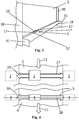
- Fig. 2 shows an example of a cutter assembly 3.
- the shown example cutter assembly 3 may be integrated with the printer 1 and arranged downstream of the printhead assembly 2 as illustrated in Fig. 1 and 3 .
- the cutter assembly 3 may be provided as an accessory that is arranged to be mounted to the printer 1, for example near the media outlet part.
- a computer program 12 is provided together with the cutter assembly accessory for driving the cutter assembly 3 may be provided.
- the computer program 12 may be provided as a software upgrade or driver or the like to be installed in the printer storage device 8 for facilitating operation of the cutter accessory.
- the example cutter assembly 3 of Fig. 2 includes cut edges 14.
- the cut edges 14 are part of cutter wheels 13.
- the example cutter assembly 3 also includes driving wheels 17 that can be used to move the cut edges 13 over the media and retain the media 4, 5 during movement.
- the shown example cutter assembly 3 is arranged to cut the media 4, 5 in two opposite directions 15, perpendicular to the media advance direction 11.
- the example cutter assembly 3 includes two cutter wheel pairs 15. Each cutter wheel pair 15 includes one cutter wheel 13 on each side of the media 4, 5, in use providing for a scissor-like cutting effect. Each pair 15 may be arranged to cut through the print media in one of the two directions 16.
- the cutter wheels 13 are arranged near the respective driving wheels 17 to cut the media 4, 5 where it is retained by the respective driving wheels 17 against a platen or guide structure 18.
- the driving wheels 17 may comprise an elastomeric or polymer surface material to on the one hand provide sufficient friction to avoid displacement of the media with respect to the cutter wheels 13 and on the other hand avoid damage to the printed image or media 4, 5.
- the example cutter assembly 3 includes a carriage 19 to which the cutter wheels 13 and the driving wheels 17 are mounted.
- a guide structure 18 is provided for guiding the carriage 19, and that supports the media and the driving wheels 17.
- the guide structure 18 is shaped as a hollow beam.
- the driving wheels 17 drive over the top surface while a lower part of the carriage 20 and the lower cutter wheels 14 may be arranged within the hollow beam.
- a drive 21 of the cutter assembly 3 is provided.
- the drive 21 includes a servo motor.
- the control circuit 6 is configured to instruct the drive 21 to drive the cutter assembly 3 while scanning the print head assembly 2 ( Fig. 1 ).
- the drive 21 includes an electro motor and a drive transmission 22.
- the drive 21 of the cutter assembly 3 may be mechanically or electrically coupled to a drive of the scanning printhead assembly 2, for example to cut during a printhead scanning action.
- the drive transmission 22 includes a belt that is connected to the carriage 19, 20, pulleys 23 and an encoder.
- the control circuit 6 may be configured to communicate with the encoder to determine a location of the carriage 19, 20.
- the control circuit 6 may be configured to determine a cutting direction based on the carriage location 19, 20 with respect to the media.
- the shown cutter assembly 3 is arranged to separate a first media portion 4 from a subsequent media portion 5 in a first cutting direction 16, and later separate the subsequent media portion 5 from a second subsequent media portion (not shown) in an opposite cutting direction 16, etc.
- Each cutting movement of the cutter assembly 3 is executed during a corresponding scanning movement of the printhead assembly 2 for printing of the respective subsequent media portion 5. In this way, a separation of the first media portion 4 is realized without interrupting a print process of the subsequent media portion 5.
- the cutter assembly 3 includes a cauterization device 24 arranged to cauterize the cut media edges of the respective media portions 4, 5 while cutting.
- cauterization may be understood as finishing the respective media edges, for example by heating, freezing, chemical agent, etc.
- a cauterization action may melt, burn, dissolve or otherwise remove protruding fibers of the media edge after cutting.
- the cauterization device 24 may be arranged to heat, freeze, provide current to, or provide a cauterization agent on the respective media portion edges to achieve a proper finishing of the media edges.
- the cauterization device 24 is provided between the cutter wheels 14 so as to cauterize after cutting in each of the two directions 16.
- the cauterization device 24 may include one or two cauterization wheels 25 or for example a finger shaped cauterization device of which the end can be heated.
- the cutter assembly 3 cuts and cauterizes the respective media edges during printing of the subsequent media portion 5, for example between two subsequent media advance movements for printing the subsequent media portion 5, for example during a printhead assembly 2 scanning action.
- the integrated cauterization device 24 allows for an integrated separation and edge finishing of the printed media portion 4 during printing of the subsequent media portion 5, that is, without interrupting a print process of the same printer.
- the cauterization device 24 may be arranged to be switched on and off to allow an operator to choose whether or not to cauterize the media portion edges during cutting.
- the carriage 19, 20 may be directly supported by a belt or the like.
- the cutter assembly 3 may include other cutting devices for cutting such as cutting blades, for example in the form of a knife or scissors, in pairs or single devices, arranged to cut in one or two directions.
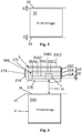
- Fig. 3 shows an example of a back side of a large format printer 1 that has a maximum media print width of more than 3 meters. In other examples of printers with cutter examples, the maximum media width may be more than 4, 5 or 6 meters.
- the cutter assembly 3 is provided downstream of a print zone.
- the cutter assembly 3 is mounted to the printer frame 30, for example through a cutter assembly frame 31.
- a carriage 19 having two pairs of driving wheels 17 is provided on top of the guide structure 18.
- the cutter assembly 3 may include cutter wheels 14, a cauterization device 18 and an inner carriage 20 these cannot be distinguished in this view.
- the cutter wheels are provided between each driving wheel pair.
- the cauterization device 24 may be provided in the middle between the driving wheel and cutter wheel pairs 15, and the inner carriage 20 may be provided under the top carriage 19, in correspondence with Fig. 2 .
- the transmission for driving the carriage 19, 20 may be provided inside the guide structure 18.
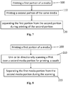
- Fig. 4 shows a diagram of a top view of media 4, 5 that advances under the printhead assembly 2 in an advance direction 11.
- the printhead assembly 2 scans over the media 4, 5 in opposite scanning directions 26 that are perpendicular to the media advance direction 11 and parallel to the cutting directions 16, printing a swath 27 on the media portion 5 after each media advance movement.
- the cutter assembly 3 cuts along a cut line 28.
- the control circuit 6 is configured to instruct (i) the printhead assembly 2 to perform a one- or two-way scanning action between two media advance movements for printing the subsequent media portion 5 and (ii) instruct the cutter assembly 3 to cut between these two media advance movements, for separating the printed media portion 4 during the scanning action and without interrupting the print process of the media portion 5 currently undergoing printing.
- Fig. 5 shows an example of print job information for printing a print image 32 on media 4 and cutting the media portion 4 that contains the image 32 and the cut line location 33.
- Fig. 5 illustrates the print job information, which may be a digital code for entry into the storage device 8.
- the cut lines locations 33 correspond to the later actual cut lines 28 and the print image 32 corresponds to a later actually printed image 34A on the printed media portion 4 (e.g. see Fig. 6 ).
- the print job information may include a desired distance D between the respective cut line locations from a point or edge of the printed image.
- the control circuit 6 is configured to receive said print job information and instruct the cutter assembly 3 to separate the first media portion 4 at said cut line location 33, when printing a subsequent media portion 5.
- the cut line location 33 may be included in the original print job information or may be received by the printer 1 at any given point in time, for example through a user interface.
- Fig. 6 shows an example of subsequent, partially overlapping swaths 27A - C of a partially printed image 34B on a media portion 5 printed subsequent to the first media portion 4.
- the first media portion 4 includes a first printed image 34A.
- the swaths 27A - C are printed after each corresponding media advance movement 11A - 11C, respectively.
- a unidirectional scanning movements or one or more bi-directional scanning movements may be executed by the printhead assembly 2 for printing the swath.
- a media advance movement 11A - 11C is executed after each scanning movement over a media width.
- a media is advanced after multiple scanning movements over the media width.
- each swath 27A - C has an equal total swath width.
- a region of each swath 27A - C overlaps a previous and/or subsequent swath 27A - C.
- more than two swaths may overlap to achieve a desired coverage.
- the patterns in the overlapping swath regions are determined by interleave masks 35A1, 35B1, 35B2, 35C1, 35C2, 35D1. These interleave masks 35A1, 35B1, 35B2, 35C1, 35C2, 35D1 are arranged so that the subsequent overlapping swaths 27A - C form a printed image 34B without banding.
- An example swath 27B includes a first interleave mask 35B1 overlapping a previously printed swath 27A and a second interleave mask 35B2 overlapping a subsequently printed swath 27C.
- the previously printed swath 27A may include a third interleave masks 35A1 overlapping an earlier printed swath 27D and a fourth interleave mask 35A2 overlapping the subsequently printed swath 27B.
- control circuit 6 may include a RIP (Raster Image Processor) or formatter configured to calculate the swath's patterns, including the patterns of the interleave masks 35A1, 35B1, 35B2, 35C1, 35C2, 35D1, and instruct the printhead assembly 2 accordingly.
- RIP Raster Image Processor
- formatter configured to calculate the swath's patterns, including the patterns of the interleave masks 35A1, 35B1, 35B2, 35C1, 35C2, 35D1, and instruct the printhead assembly 2 accordingly.
- control circuit 6 is configured to adapt at least one media advance movement 11A during the printing of the subsequent media portion 5, for aligning a predetermined cut line location 33 with respect to the cutter assembly 3.
- the preferred location 33 of the cut line 28 may be included in the original print job information, or has been entered manually through a user interface, and the distance D2 between the printhead assembly 2 and the cutter assembly 3 is fixed and predetermined
- at least one media advance movement distance d1 may be adapted so that a cut line location 33 of the media 4, 5 is aligned to the cutter assembly 3, and the first printed media 4 is separated along said cut line 28 at the preferred location 33 as provided by the print job or other input.
- the media advance movement 11A for printing the first swath 27A is shorter than the standard advance movements d2, d3 so as to make the cut line 28 correspond to the desired cut line location 33.
- control circuit 6 is configured to adjust another characteristic of at least one swath 27A, 27B for printing the subsequent media portion 5 when aligning the media 4, 5 with respect to the cutter assembly 3.
- an interleave mask 35A1 or 35B1 may be adjusted to ensure proper matching of subsequent swaths 27A, 27B.
- the interleave mask 35A1 or 35B1 may be rearranged.
- the interleave mask 35A2 may be repositioned or widened for proper matching of subsequent swaths 27A - D.
- a respective interleave mask pattern 35A2 may be rearranged for proper matching with a respective swath 27A - C.
- Multiple interleave masks 35A1, 35B1, 35B2, 35C1, 35C2, 35D1 may need to be adapted to align the media to the cutter assembly 3 so that the eventual cut line 28 at least approximately corresponds to the predetermined cut line location 33.
- Adjusting the media advance movement distance d1 and the interleave mask 35A2 may allow for separating the media during printing of a along a predetermined or input cut line location 33.
- the cut line location 33 may be (i) a standard distance from a printed image's border, (ii) entered manually or (iii) retrieved from the print job information.
- the first media portion 4 is separated without adjusting a media advance movement distance d1 - d3, for example while performing a standard printhead assembly scanning action after a standard media advance action and without changing an interleave mask characteristic.
- the cut line location is adapted to the scan and media advance characteristics of the subsequent print.
- control circuit 6 is configured to receive an immediate cut instruction, for example through a user interface, and, upon receiving such instruction, separate the first media portion 4 at a current, next or other subsequent printhead assembly scanning action. For example, a media advance movement distance or interleave mask characteristic need not be adjusted.
- the printhead assembly 2 includes a page wide array printheads instead of a scanning printhead assembly and media advance movements may be adapted or interrupted for allowing separation of the first media portion 4, for example on a predetermined cut line location 33, while the subsequent media portion 5 is being printed.
- Fig. 7 shows a flow chart of an example of a method of printing.
- the example method includes printing a first portion 4 of a media (block 100), for example forming a first printed image 34A.
- the example method includes printing a second portion 5 of the same media (block 110), for example forming the second printed image 34B.
- the example method includes separating the first portion 4 from the second portion 5 during printing of the second portion 5 (block 120).
- Fig. 8 shows a flow chart of a further example of a method of printing.
- the example method includes printing a first media portion 4 (block 200).
- the example method includes executing a unidirectional scanning movement or one or more two-way scanning movements of the printhead assembly 2 for printing a swath 27A, 27E over the second portion 5 (block 210).
- the example method includes separating the first portion 4 from the second portion 5 during the scanning movement (block 220), with the cutter assembly 3. For example, the cutter assembly 3 moves while the scanning movements are being executed, between two subsequent media advance movements 11A - 11D, approximately parallel to the printhead assembly 2.
- Fig. 9 shows a flow chart of another example of a method of printing.
- the control circuit 6 receives first and second print job information (block 300), for example through a wired or wireless connection or from a second storage device.
- at least one of the first and second print job information includes a cut line location 33 for separating the first media portion 4 from the second media portion 5.
- the example method includes printing the first print job on the first media portion 4 (block 310). This results in the first printed image 34A.
- the example method includes at least partially printing the second print job on the second media portion 5 (block 320), providing for the second, partially printed image 34B.
- the example method includes adjusting at least one swath characteristic of the second print job so that the cutter assembly 3 is aligned (block 330).
- the swath characteristic may be at least one of a media advance movement distance d1 and an interleave mask characteristic.
- the interleave mask characteristic may include a repositioning and a rearrangement of the interleave mask 35A1, 35B1, 35B2, 35C1, 35C2, 35D1.
- the cauterization device 24 is switched on before cutting.
- the example method may include scanning the printhead assembly 2 to print the adapted swath and in parallel move the cutter assembly 3 to cut and cauterize the respective borders of the media portions 4, 5 along the cut line 28 (block 340).
- Fig. 10 shows a flow chart of an example of a method of cutting media.
- media is advanced between swaths 27A - D for printing the second media portion 5 (block 400).
- the printer 1 receives an immediate cut instruction (block 410), for example through a user interface.
- the first media portion 4 is separated from the second media portion 5 by executing a cut action during the next scanning action (block 420). The cut action was executed during the scanning action of the printhead assembly 2, so that no printing efficiency was lost in the process.
Landscapes
- Engineering & Computer Science (AREA)
- Physics & Mathematics (AREA)
- Mathematical Physics (AREA)
- General Engineering & Computer Science (AREA)
- General Physics & Mathematics (AREA)
- Theoretical Computer Science (AREA)
- Handling Of Sheets (AREA)
- Life Sciences & Earth Sciences (AREA)
- Forests & Forestry (AREA)
- Mechanical Engineering (AREA)
Claims (13)
- Imprimante comprenant
un ensemble de tête d'impression (2) et
un ensemble de coupe (3) agencé en aval de l'ensemble de tête d'impression (2), caractérisé en ce qu'il comprend
un circuit de commande (6) configuré pour ordonner à l'ensemble de coupe (3) de séparer une première portion de support imprimée (4) d'une portion de support suivante (5) pendant l'impression de la portion de support suivante (5). - Imprimante selon la revendication 1, dans laquelle le circuit de commande (6) est configuré pour adapter une caractéristique de bande pendant l'impression de la portion de support suivante (5) pour positionner les portions de support (4, 5) par rapport à un emplacement de ligne de coupe (33) entre la première portion de support imprimée (4) et la portion de support suivante (5), pendant l'impression de la portion de support suivante (5).
- Imprimante selon la revendication 1, dans laquelle le circuit de commande (6) est configuré pour ajuster une distance de mouvement d'avance du support (d1) pour aligner les portions de support (4, 5) par rapport à l'ensemble de coupe (3), en correspondance avec un emplacement de ligne de coupe prédéterminé (33).
- Imprimante selon la revendication 3, dans laquelle le circuit de commande (6) est configuré pour ajuster une caractéristique de masque d'entrelacement d'au moins une bande pour faire correspondre des bandes suivantes lorsqu'une distance de mouvement d'avance du support (d1) a été ajustée.
- Imprimante selon la revendication 1, dans laquelle le circuit de commande (6) est configuré pour ordonner à l'ensemble de coupe (3) de couper tout en balayant l'ensemble de tête d'impression (2) pour imprimer la portion de support suivante (5).
- Imprimante selon la revendication 1, dans laquelle le circuit de commande (6) est configuré pour
recevoir des informations sur le travail d'impression qui comportent un emplacement de ligne de coupe (33) par rapport à une image d'impression, et
ordonner à l'ensemble de coupe (3) de séparer la première portion de support (4) audit emplacement de ligne de coupe (33). - Imprimante selon la revendication 1, dans laquelle le circuit de commande (6) est configuré pour
recevoir une instruction de coupe immédiate, et
lors de la réception de ladite instruction de découpe immédiate, séparer la première portion de support (4) durant une prochaine action de balayage de tête d'impression. - Imprimante selon la revendication 1, dans laquelle l'ensemble de coupe (3) est agencé pour couper dans deux directions opposées (15), perpendiculaires à la direction d'avance du support (11).
- Imprimante selon la revendication 1, dans laquelle l'ensemble de coupe (3) comprend un dispositif de cautérisation (24) agencé pour cautériser pendant la découpe.
- Imprimante selon la revendication 1, dans laquelle l'ensemble de coupe (3) comprend
au moins un bord coupé (14),
des roues (13, 15, 17),
un chariot (19) pour porter l'au moins un bord coupé et des roues, et
une structure de guidage (18) pour guider le chariot (19) sur une ligne de coupe pour couper le support. - Procédé d'impression, comprenant
l'impression d'une première portion (4) d'un support au moyen d'une imprimante,
l'impression d'une seconde portion (5) du support au moyen de la même imprimante, et
la séparation de la première portion (4) de la seconde portion (5) pendant l'impression de la seconde portion (5). - Procédé selon la revendication 11, comprenant la séparation de la première portion (4) de la seconde portion (5) tout en exécutant un mouvement de balayage unidirectionnel ou bidirectionnel d'une tête d'impression (2) pour imprimer une bande de la seconde portion (5).
- Programme informatique destiné à être exécuté sur un circuit de commande (6) d'une imprimante, comprenant un code configuré pour ordonner à un circuit de commande (6) d'ordonner à un ensemble de coupe (3) d'une imprimante respective de séparer une première portion de support imprimé (4) d'une portion de support suivante (5) pendant l'impression de la portion de support suivante (5).
Applications Claiming Priority (1)
| Application Number | Priority Date | Filing Date | Title |
|---|---|---|---|
| PCT/US2011/067975 WO2013101126A1 (fr) | 2011-12-29 | 2011-12-29 | Découpe de supports |
Publications (3)
| Publication Number | Publication Date |
|---|---|
| EP2797752A1 EP2797752A1 (fr) | 2014-11-05 |
| EP2797752A4 EP2797752A4 (fr) | 2015-05-13 |
| EP2797752B1 true EP2797752B1 (fr) | 2020-02-19 |
Family
ID=48698360
Family Applications (1)
| Application Number | Title | Priority Date | Filing Date |
|---|---|---|---|
| EP11878887.6A Active EP2797752B1 (fr) | 2011-12-29 | 2011-12-29 | Découpe de supports |
Country Status (4)
| Country | Link |
|---|---|
| US (1) | US9227436B2 (fr) |
| EP (1) | EP2797752B1 (fr) |
| CN (1) | CN104136227B (fr) |
| WO (1) | WO2013101126A1 (fr) |
Families Citing this family (9)
| Publication number | Priority date | Publication date | Assignee | Title |
|---|---|---|---|---|
| EP2921309A1 (fr) * | 2014-03-20 | 2015-09-23 | Matan Digital Printing Ltd | Procédé et système pour sectionner une maquette d'un support |
| CN106232370B (zh) | 2014-04-23 | 2019-03-19 | 惠普发展公司,有限责任合伙企业 | 打印机和打印方法 |
| JP6471595B2 (ja) * | 2015-04-13 | 2019-02-20 | 株式会社リコー | 画像形成装置 |
| JP6694331B2 (ja) * | 2016-06-07 | 2020-05-13 | ローランドディー.ジー.株式会社 | 加工方法及び加工システム |
| CN110494293B (zh) * | 2017-06-20 | 2021-06-11 | 惠普发展公司,有限责任合伙企业 | 切割打印基材 |
| WO2019198497A1 (fr) * | 2018-04-09 | 2019-10-17 | ローランドディー.ジー.株式会社 | Imprimante et système d'impression |
| CN113795388A (zh) * | 2019-05-16 | 2021-12-14 | 惠普发展公司,有限责任合伙企业 | 打印和切割 |
| CN112962300B (zh) * | 2021-02-10 | 2022-04-15 | 金恒丰科技集团有限公司 | 一种切刀装置及打印机 |
| US11861434B2 (en) * | 2021-10-07 | 2024-01-02 | Kyocera Document Solutions Inc. | Image processing apparatus, image forming apparatus, and image processing method for drawing on cross-section to be trimmed |
Citations (1)
| Publication number | Priority date | Publication date | Assignee | Title |
|---|---|---|---|---|
| JP2003145483A (ja) * | 2001-11-19 | 2003-05-20 | Takamasa Onishi | シート材切断装置 |
Family Cites Families (20)
| Publication number | Priority date | Publication date | Assignee | Title |
|---|---|---|---|---|
| JP3166206B2 (ja) * | 1990-08-29 | 2001-05-14 | セイコーエプソン株式会社 | テーププリンタ及びその制御方法 |
| JP2861835B2 (ja) * | 1994-11-29 | 1999-02-24 | 日本電気株式会社 | 印刷装置 |
| US5911530A (en) | 1997-09-02 | 1999-06-15 | Hewlett-Packard Company | Wheel-driven rotary cutter for printer |
| JP3608604B2 (ja) * | 1998-01-08 | 2005-01-12 | セイコーエプソン株式会社 | シリアル記録装置 |
| US6315474B1 (en) * | 1998-10-30 | 2001-11-13 | Hewlett-Packard Company | Automatic paper cutter for large format printer |
| JP2002001693A (ja) * | 2000-06-21 | 2002-01-08 | Mitsuo Fujisawa | シート材又は紐状体及びその切断装置 |
| JP4452392B2 (ja) | 2000-09-29 | 2010-04-21 | セイコーエプソン株式会社 | テープ印刷装置 |
| US6860662B2 (en) * | 2001-03-30 | 2005-03-01 | Seiko Epson Corporation | Printing apparatus and method for processing a predetermined location on a printed sheet and a driver program therefor |
| JP3915887B2 (ja) * | 2001-10-04 | 2007-05-16 | セイコーエプソン株式会社 | ロール紙切断制御方法、及びインクジェット式記録装置 |
| JP4093876B2 (ja) | 2003-02-05 | 2008-06-04 | 富士通コンポーネント株式会社 | カッタ部を備えたプリンタ |
| JP4579788B2 (ja) | 2005-08-08 | 2010-11-10 | キヤノン株式会社 | シート処理装置及び画像形成装置 |
| JP4395788B2 (ja) | 2006-10-10 | 2010-01-13 | セイコーエプソン株式会社 | カッター装置及び該カッター装置を備えた記録装置 |
| JP4865493B2 (ja) | 2006-10-13 | 2012-02-01 | 三菱重工印刷紙工機械株式会社 | 印刷機およびその運転方法 |
| US7815382B2 (en) * | 2007-01-26 | 2010-10-19 | Hewlett-Packard Development Company, L.P. | Cutter assembly for a printer |
| JP2010023387A (ja) | 2008-07-23 | 2010-02-04 | Seiko Epson Corp | プリンタにおける記録紙の切断方法およびプリンタ |
| JP5454087B2 (ja) | 2009-11-02 | 2014-03-26 | セイコーエプソン株式会社 | カッター付きプリンター |
| JP2011131492A (ja) * | 2009-12-24 | 2011-07-07 | Canon Finetech Inc | 記録装置および記録装置の制御方法 |
| JP5120791B2 (ja) * | 2010-04-12 | 2013-01-16 | コニカミノルタホールディングス株式会社 | 画像記録装置 |
| JP5786456B2 (ja) * | 2011-05-24 | 2015-09-30 | セイコーエプソン株式会社 | 液体吐出装置、及び、液体吐出方法 |
| US8864394B2 (en) * | 2011-12-22 | 2014-10-21 | Hewlett-Packard Industrial Printing Ltd. | Printer substrate edge trimming |
-
2011
- 2011-12-29 EP EP11878887.6A patent/EP2797752B1/fr active Active
- 2011-12-29 CN CN201180076476.8A patent/CN104136227B/zh not_active Expired - Fee Related
- 2011-12-29 WO PCT/US2011/067975 patent/WO2013101126A1/fr not_active Ceased
- 2011-12-29 US US14/368,274 patent/US9227436B2/en active Active
Patent Citations (1)
| Publication number | Priority date | Publication date | Assignee | Title |
|---|---|---|---|---|
| JP2003145483A (ja) * | 2001-11-19 | 2003-05-20 | Takamasa Onishi | シート材切断装置 |
Also Published As
| Publication number | Publication date |
|---|---|
| EP2797752A1 (fr) | 2014-11-05 |
| CN104136227A (zh) | 2014-11-05 |
| WO2013101126A1 (fr) | 2013-07-04 |
| EP2797752A4 (fr) | 2015-05-13 |
| US9227436B2 (en) | 2016-01-05 |
| US20140374980A1 (en) | 2014-12-25 |
| CN104136227B (zh) | 2017-06-13 |
Similar Documents
| Publication | Publication Date | Title |
|---|---|---|
| EP2797752B1 (fr) | Découpe de supports | |
| JP5370058B2 (ja) | 記録媒体の搬送制御方法およびプリンター | |
| CN102574403B (zh) | 打印裁切机 | |
| JP2011051192A (ja) | カッティング装置およびそのカット方法 | |
| CN106232370B (zh) | 打印机和打印方法 | |
| EP2819849B1 (fr) | Découpe d'un milieu en mouvement | |
| US12269260B2 (en) | Printing and cutting | |
| CN110494293B (zh) | 切割打印基材 | |
| JP5437099B2 (ja) | 画像形成装置における画像形成方法および画像形成用コンピュータプログラム | |
| JP3856098B2 (ja) | ロール紙切断制御方法、及びインクジェット式記録装置 | |
| JP2011131492A (ja) | 記録装置および記録装置の制御方法 | |
| JP2017080917A (ja) | 印刷装置の制御方法および印刷装置 | |
| JP3915887B2 (ja) | ロール紙切断制御方法、及びインクジェット式記録装置 | |
| JP2016179635A (ja) | プリンタ | |
| JP4803388B2 (ja) | 装置、プログラム | |
| JP6344130B2 (ja) | 印刷制御装置及びプログラム | |
| JP2011148248A (ja) | カッター機構、プリンター、及びカッター機構の制御方法 | |
| JP3940900B2 (ja) | 印刷用紙切断制御方法、印刷装置、印刷用紙切断制御プログラム | |
| JP5650481B2 (ja) | ラベルプリンタ | |
| JP4544049B2 (ja) | 画像記録装置 | |
| JP3968557B2 (ja) | ロール紙切断制御方法及びインクジェット式記録装置 | |
| JP2019123184A (ja) | 媒体切断方法及び記録装置 | |
| JP5605407B2 (ja) | プリンタ及びプリンタの制御方法 | |
| JPH0493272A (ja) | プリンタの複数連続帳票切替え機構 |
Legal Events
| Date | Code | Title | Description |
|---|---|---|---|
| PUAI | Public reference made under article 153(3) epc to a published international application that has entered the european phase |
Free format text: ORIGINAL CODE: 0009012 |
|
| 17P | Request for examination filed |
Effective date: 20140620 |
|
| AK | Designated contracting states |
Kind code of ref document: A1 Designated state(s): AL AT BE BG CH CY CZ DE DK EE ES FI FR GB GR HR HU IE IS IT LI LT LU LV MC MK MT NL NO PL PT RO RS SE SI SK SM TR |
|
| DAX | Request for extension of the european patent (deleted) | ||
| RA4 | Supplementary search report drawn up and despatched (corrected) |
Effective date: 20150415 |
|
| RIC1 | Information provided on ipc code assigned before grant |
Ipc: B26D 7/00 20060101ALI20150409BHEP Ipc: B41J 11/66 20060101ALI20150409BHEP Ipc: B41J 29/38 20060101ALI20150409BHEP Ipc: B26D 7/27 20060101ALI20150409BHEP Ipc: B41J 11/70 20060101AFI20150409BHEP |
|
| STAA | Information on the status of an ep patent application or granted ep patent |
Free format text: STATUS: EXAMINATION IS IN PROGRESS |
|
| 17Q | First examination report despatched |
Effective date: 20190111 |
|
| RAP1 | Party data changed (applicant data changed or rights of an application transferred) |
Owner name: HEWLETT-PACKARD DEVELOPMENT COMPANY, L.P. |
|
| GRAP | Despatch of communication of intention to grant a patent |
Free format text: ORIGINAL CODE: EPIDOSNIGR1 |
|
| STAA | Information on the status of an ep patent application or granted ep patent |
Free format text: STATUS: GRANT OF PATENT IS INTENDED |
|
| INTG | Intention to grant announced |
Effective date: 20190926 |
|
| GRAS | Grant fee paid |
Free format text: ORIGINAL CODE: EPIDOSNIGR3 |
|
| GRAA | (expected) grant |
Free format text: ORIGINAL CODE: 0009210 |
|
| STAA | Information on the status of an ep patent application or granted ep patent |
Free format text: STATUS: THE PATENT HAS BEEN GRANTED |
|
| AK | Designated contracting states |
Kind code of ref document: B1 Designated state(s): AL AT BE BG CH CY CZ DE DK EE ES FI FR GB GR HR HU IE IS IT LI LT LU LV MC MK MT NL NO PL PT RO RS SE SI SK SM TR |
|
| REG | Reference to a national code |
Ref country code: GB Ref legal event code: FG4D |
|
| REG | Reference to a national code |
Ref country code: CH Ref legal event code: EP |
|
| REG | Reference to a national code |
Ref country code: DE Ref legal event code: R096 Ref document number: 602011065150 Country of ref document: DE |
|
| REG | Reference to a national code |
Ref country code: DE Ref legal event code: R082 Ref document number: 602011065150 Country of ref document: DE Representative=s name: SCHOPPE, ZIMMERMANN, STOECKELER, ZINKLER, SCHE, DE |
|
| REG | Reference to a national code |
Ref country code: AT Ref legal event code: REF Ref document number: 1234499 Country of ref document: AT Kind code of ref document: T Effective date: 20200315 |
|
| REG | Reference to a national code |
Ref country code: IE Ref legal event code: FG4D |
|
| REG | Reference to a national code |
Ref country code: NL Ref legal event code: FP |
|
| PG25 | Lapsed in a contracting state [announced via postgrant information from national office to epo] |
Ref country code: RS Free format text: LAPSE BECAUSE OF FAILURE TO SUBMIT A TRANSLATION OF THE DESCRIPTION OR TO PAY THE FEE WITHIN THE PRESCRIBED TIME-LIMIT Effective date: 20200219 Ref country code: FI Free format text: LAPSE BECAUSE OF FAILURE TO SUBMIT A TRANSLATION OF THE DESCRIPTION OR TO PAY THE FEE WITHIN THE PRESCRIBED TIME-LIMIT Effective date: 20200219 Ref country code: NO Free format text: LAPSE BECAUSE OF FAILURE TO SUBMIT A TRANSLATION OF THE DESCRIPTION OR TO PAY THE FEE WITHIN THE PRESCRIBED TIME-LIMIT Effective date: 20200519 |
|
| REG | Reference to a national code |
Ref country code: LT Ref legal event code: MG4D |
|
| PG25 | Lapsed in a contracting state [announced via postgrant information from national office to epo] |
Ref country code: BG Free format text: LAPSE BECAUSE OF FAILURE TO SUBMIT A TRANSLATION OF THE DESCRIPTION OR TO PAY THE FEE WITHIN THE PRESCRIBED TIME-LIMIT Effective date: 20200519 Ref country code: IS Free format text: LAPSE BECAUSE OF FAILURE TO SUBMIT A TRANSLATION OF THE DESCRIPTION OR TO PAY THE FEE WITHIN THE PRESCRIBED TIME-LIMIT Effective date: 20200619 Ref country code: GR Free format text: LAPSE BECAUSE OF FAILURE TO SUBMIT A TRANSLATION OF THE DESCRIPTION OR TO PAY THE FEE WITHIN THE PRESCRIBED TIME-LIMIT Effective date: 20200520 Ref country code: HR Free format text: LAPSE BECAUSE OF FAILURE TO SUBMIT A TRANSLATION OF THE DESCRIPTION OR TO PAY THE FEE WITHIN THE PRESCRIBED TIME-LIMIT Effective date: 20200219 Ref country code: LV Free format text: LAPSE BECAUSE OF FAILURE TO SUBMIT A TRANSLATION OF THE DESCRIPTION OR TO PAY THE FEE WITHIN THE PRESCRIBED TIME-LIMIT Effective date: 20200219 Ref country code: SE Free format text: LAPSE BECAUSE OF FAILURE TO SUBMIT A TRANSLATION OF THE DESCRIPTION OR TO PAY THE FEE WITHIN THE PRESCRIBED TIME-LIMIT Effective date: 20200219 |
|
| PG25 | Lapsed in a contracting state [announced via postgrant information from national office to epo] |
Ref country code: SK Free format text: LAPSE BECAUSE OF FAILURE TO SUBMIT A TRANSLATION OF THE DESCRIPTION OR TO PAY THE FEE WITHIN THE PRESCRIBED TIME-LIMIT Effective date: 20200219 Ref country code: PT Free format text: LAPSE BECAUSE OF FAILURE TO SUBMIT A TRANSLATION OF THE DESCRIPTION OR TO PAY THE FEE WITHIN THE PRESCRIBED TIME-LIMIT Effective date: 20200712 Ref country code: SM Free format text: LAPSE BECAUSE OF FAILURE TO SUBMIT A TRANSLATION OF THE DESCRIPTION OR TO PAY THE FEE WITHIN THE PRESCRIBED TIME-LIMIT Effective date: 20200219 Ref country code: EE Free format text: LAPSE BECAUSE OF FAILURE TO SUBMIT A TRANSLATION OF THE DESCRIPTION OR TO PAY THE FEE WITHIN THE PRESCRIBED TIME-LIMIT Effective date: 20200219 Ref country code: DK Free format text: LAPSE BECAUSE OF FAILURE TO SUBMIT A TRANSLATION OF THE DESCRIPTION OR TO PAY THE FEE WITHIN THE PRESCRIBED TIME-LIMIT Effective date: 20200219 Ref country code: LT Free format text: LAPSE BECAUSE OF FAILURE TO SUBMIT A TRANSLATION OF THE DESCRIPTION OR TO PAY THE FEE WITHIN THE PRESCRIBED TIME-LIMIT Effective date: 20200219 Ref country code: RO Free format text: LAPSE BECAUSE OF FAILURE TO SUBMIT A TRANSLATION OF THE DESCRIPTION OR TO PAY THE FEE WITHIN THE PRESCRIBED TIME-LIMIT Effective date: 20200219 Ref country code: CZ Free format text: LAPSE BECAUSE OF FAILURE TO SUBMIT A TRANSLATION OF THE DESCRIPTION OR TO PAY THE FEE WITHIN THE PRESCRIBED TIME-LIMIT Effective date: 20200219 Ref country code: ES Free format text: LAPSE BECAUSE OF FAILURE TO SUBMIT A TRANSLATION OF THE DESCRIPTION OR TO PAY THE FEE WITHIN THE PRESCRIBED TIME-LIMIT Effective date: 20200219 |
|
| REG | Reference to a national code |
Ref country code: AT Ref legal event code: MK05 Ref document number: 1234499 Country of ref document: AT Kind code of ref document: T Effective date: 20200219 |
|
| REG | Reference to a national code |
Ref country code: DE Ref legal event code: R097 Ref document number: 602011065150 Country of ref document: DE |
|
| PLBE | No opposition filed within time limit |
Free format text: ORIGINAL CODE: 0009261 |
|
| STAA | Information on the status of an ep patent application or granted ep patent |
Free format text: STATUS: NO OPPOSITION FILED WITHIN TIME LIMIT |
|
| 26N | No opposition filed |
Effective date: 20201120 |
|
| PG25 | Lapsed in a contracting state [announced via postgrant information from national office to epo] |
Ref country code: AT Free format text: LAPSE BECAUSE OF FAILURE TO SUBMIT A TRANSLATION OF THE DESCRIPTION OR TO PAY THE FEE WITHIN THE PRESCRIBED TIME-LIMIT Effective date: 20200219 |
|
| PG25 | Lapsed in a contracting state [announced via postgrant information from national office to epo] |
Ref country code: PL Free format text: LAPSE BECAUSE OF FAILURE TO SUBMIT A TRANSLATION OF THE DESCRIPTION OR TO PAY THE FEE WITHIN THE PRESCRIBED TIME-LIMIT Effective date: 20200219 Ref country code: SI Free format text: LAPSE BECAUSE OF FAILURE TO SUBMIT A TRANSLATION OF THE DESCRIPTION OR TO PAY THE FEE WITHIN THE PRESCRIBED TIME-LIMIT Effective date: 20200219 |
|
| REG | Reference to a national code |
Ref country code: CH Ref legal event code: PL |
|
| PG25 | Lapsed in a contracting state [announced via postgrant information from national office to epo] |
Ref country code: MC Free format text: LAPSE BECAUSE OF FAILURE TO SUBMIT A TRANSLATION OF THE DESCRIPTION OR TO PAY THE FEE WITHIN THE PRESCRIBED TIME-LIMIT Effective date: 20200219 |
|
| REG | Reference to a national code |
Ref country code: BE Ref legal event code: MM Effective date: 20201231 |
|
| PG25 | Lapsed in a contracting state [announced via postgrant information from national office to epo] |
Ref country code: IE Free format text: LAPSE BECAUSE OF NON-PAYMENT OF DUE FEES Effective date: 20201229 Ref country code: LU Free format text: LAPSE BECAUSE OF NON-PAYMENT OF DUE FEES Effective date: 20201229 |
|
| PG25 | Lapsed in a contracting state [announced via postgrant information from national office to epo] |
Ref country code: LI Free format text: LAPSE BECAUSE OF NON-PAYMENT OF DUE FEES Effective date: 20201231 Ref country code: CH Free format text: LAPSE BECAUSE OF NON-PAYMENT OF DUE FEES Effective date: 20201231 |
|
| PGFP | Annual fee paid to national office [announced via postgrant information from national office to epo] |
Ref country code: GB Payment date: 20211118 Year of fee payment: 11 Ref country code: FR Payment date: 20211117 Year of fee payment: 11 Ref country code: NL Payment date: 20211118 Year of fee payment: 11 |
|
| PG25 | Lapsed in a contracting state [announced via postgrant information from national office to epo] |
Ref country code: IT Free format text: LAPSE BECAUSE OF NON-PAYMENT OF DUE FEES Effective date: 20201229 |
|
| PG25 | Lapsed in a contracting state [announced via postgrant information from national office to epo] |
Ref country code: TR Free format text: LAPSE BECAUSE OF FAILURE TO SUBMIT A TRANSLATION OF THE DESCRIPTION OR TO PAY THE FEE WITHIN THE PRESCRIBED TIME-LIMIT Effective date: 20200219 Ref country code: MT Free format text: LAPSE BECAUSE OF FAILURE TO SUBMIT A TRANSLATION OF THE DESCRIPTION OR TO PAY THE FEE WITHIN THE PRESCRIBED TIME-LIMIT Effective date: 20200219 Ref country code: CY Free format text: LAPSE BECAUSE OF FAILURE TO SUBMIT A TRANSLATION OF THE DESCRIPTION OR TO PAY THE FEE WITHIN THE PRESCRIBED TIME-LIMIT Effective date: 20200219 |
|
| PG25 | Lapsed in a contracting state [announced via postgrant information from national office to epo] |
Ref country code: MK Free format text: LAPSE BECAUSE OF FAILURE TO SUBMIT A TRANSLATION OF THE DESCRIPTION OR TO PAY THE FEE WITHIN THE PRESCRIBED TIME-LIMIT Effective date: 20200219 Ref country code: AL Free format text: LAPSE BECAUSE OF FAILURE TO SUBMIT A TRANSLATION OF THE DESCRIPTION OR TO PAY THE FEE WITHIN THE PRESCRIBED TIME-LIMIT Effective date: 20200219 |
|
| PG25 | Lapsed in a contracting state [announced via postgrant information from national office to epo] |
Ref country code: BE Free format text: LAPSE BECAUSE OF NON-PAYMENT OF DUE FEES Effective date: 20201231 |
|
| REG | Reference to a national code |
Ref country code: NL Ref legal event code: MM Effective date: 20230101 |
|
| GBPC | Gb: european patent ceased through non-payment of renewal fee |
Effective date: 20221229 |
|
| PG25 | Lapsed in a contracting state [announced via postgrant information from national office to epo] |
Ref country code: NL Free format text: LAPSE BECAUSE OF NON-PAYMENT OF DUE FEES Effective date: 20230101 |
|
| PG25 | Lapsed in a contracting state [announced via postgrant information from national office to epo] |
Ref country code: GB Free format text: LAPSE BECAUSE OF NON-PAYMENT OF DUE FEES Effective date: 20221229 |
|
| PG25 | Lapsed in a contracting state [announced via postgrant information from national office to epo] |
Ref country code: FR Free format text: LAPSE BECAUSE OF NON-PAYMENT OF DUE FEES Effective date: 20221231 |
|
| REG | Reference to a national code |
Ref country code: DE Ref legal event code: R082 Ref document number: 602011065150 Country of ref document: DE Representative=s name: NOVAGRAAF BREVETS, FR |
|
| PGFP | Annual fee paid to national office [announced via postgrant information from national office to epo] |
Ref country code: DE Payment date: 20251126 Year of fee payment: 15 |