EP2798228B1 - Strömungsmischungsvorrichtung und Verfahren zum Mischen dieser Strömungen - Google Patents
Strömungsmischungsvorrichtung und Verfahren zum Mischen dieser Strömungen Download PDFInfo
- Publication number
- EP2798228B1 EP2798228B1 EP12871717.0A EP12871717A EP2798228B1 EP 2798228 B1 EP2798228 B1 EP 2798228B1 EP 12871717 A EP12871717 A EP 12871717A EP 2798228 B1 EP2798228 B1 EP 2798228B1
- Authority
- EP
- European Patent Office
- Prior art keywords
- working fluid
- fluid
- passage
- utility
- flow
- Prior art date
- Legal status (The legal status is an assumption and is not a legal conclusion. Google has not performed a legal analysis and makes no representation as to the accuracy of the status listed.)
- Active
Links
Images

Classifications
-
- F—MECHANICAL ENGINEERING; LIGHTING; HEATING; WEAPONS; BLASTING
- F02—COMBUSTION ENGINES; HOT-GAS OR COMBUSTION-PRODUCT ENGINE PLANTS
- F02C—GAS-TURBINE PLANTS; AIR INTAKES FOR JET-PROPULSION PLANTS; CONTROLLING FUEL SUPPLY IN AIR-BREATHING JET-PROPULSION PLANTS
- F02C7/00—Features, components parts, details or accessories, not provided for in, or of interest apart form groups F02C1/00 - F02C6/00; Air intakes for jet-propulsion plants
- F02C7/06—Arrangements of bearings; Lubricating
-
- F—MECHANICAL ENGINEERING; LIGHTING; HEATING; WEAPONS; BLASTING
- F15—FLUID-PRESSURE ACTUATORS; HYDRAULICS OR PNEUMATICS IN GENERAL
- F15D—FLUID DYNAMICS, i.e. METHODS OR MEANS FOR INFLUENCING THE FLOW OF GASES OR LIQUIDS
- F15D1/00—Influencing flow of fluids
- F15D1/02—Influencing flow of fluids in pipes or conduits
-
- F—MECHANICAL ENGINEERING; LIGHTING; HEATING; WEAPONS; BLASTING
- F16—ENGINEERING ELEMENTS AND UNITS; GENERAL MEASURES FOR PRODUCING AND MAINTAINING EFFECTIVE FUNCTIONING OF MACHINES OR INSTALLATIONS; THERMAL INSULATION IN GENERAL
- F16L—PIPES; JOINTS OR FITTINGS FOR PIPES; SUPPORTS FOR PIPES, CABLES OR PROTECTIVE TUBING; MEANS FOR THERMAL INSULATION IN GENERAL
- F16L41/00—Branching pipes; Joining pipes to walls
- F16L41/02—Branch units, e.g. made in one piece, welded, riveted
- F16L41/021—T- or cross-pieces
-
- F—MECHANICAL ENGINEERING; LIGHTING; HEATING; WEAPONS; BLASTING
- F05—INDEXING SCHEMES RELATING TO ENGINES OR PUMPS IN VARIOUS SUBCLASSES OF CLASSES F01-F04
- F05D—INDEXING SCHEME FOR ASPECTS RELATING TO NON-POSITIVE-DISPLACEMENT MACHINES OR ENGINES, GAS-TURBINES OR JET-PROPULSION PLANTS
- F05D2260/00—Function
- F05D2260/60—Fluid transfer
- F05D2260/601—Fluid transfer using an ejector or a jet pump
-
- F—MECHANICAL ENGINEERING; LIGHTING; HEATING; WEAPONS; BLASTING
- F05—INDEXING SCHEMES RELATING TO ENGINES OR PUMPS IN VARIOUS SUBCLASSES OF CLASSES F01-F04
- F05D—INDEXING SCHEME FOR ASPECTS RELATING TO NON-POSITIVE-DISPLACEMENT MACHINES OR ENGINES, GAS-TURBINES OR JET-PROPULSION PLANTS
- F05D2260/00—Function
- F05D2260/60—Fluid transfer
- F05D2260/602—Drainage
Definitions
- the present invention generally relates to gas turbine engine working fluid systems, and more particularly, but not exclusively, to gas turbine engine systems that merge fluid flow streams.
- US4555902 discloses a heat recovery system for supplementing the exhaust mass flow from a gas turbine with additional flow of preheated air to provide greater steam output from a heat recovery unit such as a steam generator.
- EP1408280 discloses a swirler including a tubular body having a row of secondary radial swirl vanes.
- US3178882 discloses a supercharger for internal combustion engines and, in particular, an improved type of supercharger and improved method for providing a combustible mixture to engines by utilisation of improved supercharging principles.
- US4020632 discloses a gas turbine engine fuel delivery.
- One embodiment of the present invention is an apparatus according to claim 1 and another embodiment is a method according to claim 14. Further embodiments, forms, features, aspects, benefits, and advantages of the present application shall become apparent from the description and figures provided herewith.
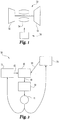
- a gas turbine engine 50 having a compressor 52, combustor 54, and turbine 56 which together operate to provide power and/or thrust, among other potential uses.
- the gas turbine engine is depicted as a single spool turbojet engine in the illustrated embodiment but other embodiments can take on any variety of forms.
- the gas turbine engine 50 can have multiple spools configured to have any number of rotating turbomachinery components, and alternatively and/or additional can be arranged as a turbofan, turboshaft, or turboprop engine.
- the gas turbine engine can be adaptive and/or configurable cycle engine, and furthermore can be integrated with any number of systems.
- the gas turbine engine 50 has any number of uses and can take on any variety of embodiments.
- the gas turbine engine 50 is coupled with an aircraft to provide power.
- aircraft includes, but is not limited to, helicopters, airplanes, unmanned space vehicles, fixed wing vehicles, variable wing vehicles, rotary wing vehicles, unmanned combat aerial vehicles, tailless aircraft, hover crafts, and other airborne and/or extraterrestrial (spacecraft) vehicles.
- present inventions are contemplated for utilization in other applications that may not be coupled with an aircraft such as, for example, industrial applications, power generation, pumping sets, naval propulsion, weapon systems, security systems, perimeter defense/security systems, and the like known to one of ordinary skill in the art.
- the gas turbine engine 50 of FIG. 1 is depicted as having a working fluid system 58 useful to provide a working fluid to components and systems of, or coupled to, the gas turbine engine 50, some of which will be described further below.
- the working fluid system 58 can provide a supply of working fluid in a close circuit.
- the working fluid system 58 operates such that the working fluid recirculates within the system during operation of the gas turbine engine 50.
- the working fluid can take on a variety of forms and can be useful in a number of different manners.
- the working fluid can have usefulness in providing lubrication and/or heat transfer to the components and systems. Reference will be made below to a lubricant but no limitation is hereby intended as to the type of useful working fluid used in the system.
- the lubricant provided by the lubrication system 58 can flow within the system through any number of passageways that can have flow splits and flow mergers. These passageways can be created by conduits such as hoses and ducts that can be connected with other structures that provide lubricant to various components and structures of or coupled to the gas turbine engine or related accessories.
- the lubricant used in the lubrication system can be used primarily to facilitate relative movement of coupled parts.
- the lubricant can have a subsidiary purpose of transferring heat from relatively high temperature regions to relatively low temperature regions of the coupled parts, gas turbine engine, related accessories, etc.
- the lubricant can have a primary role of facilitating heat transfer, such as cooling, with a subsidiary role of facilitating relative movement of parts.
- the lubricant can be an oil, whether natural, synthetic, processed, etc. and can have any variety of characteristics.
- FIG. 2 One form of the working fluid system 58 is shown in FIG. 2 and includes a flow union member 60 that is shown as receiving a left side flow of lubricant 62 and a right side flow of lubricant 64.
- a flow union member 60 that is shown as receiving a left side flow of lubricant 62 and a right side flow of lubricant 64.
- the flow union member 60 is used to combine the left side flow 62 and the right side flow 64 to produce a combined flow 66 shown exiting the flow union member 60.
- An embodiment of the flow union member 60 will be shown below in FIG. 3 .
- the combined flow 66 is received by a filter 68 that can be used to recondition the working fluid and remove particulates that may be in the working fluid.
- the filter 68 can take a variety of forms such as a media based filter and a centrifugal type filter, among potential others.
- the filter 68 is depicted as a single block in the illustrated embodiment but additional filters arranged in series and/or in parallel can also be used.
- the filter 68 can be a scavenge oil filter for the gas turbine engine 50.
- the filter 68 provide working fluid to a fluid mover 70 that assists in propelling the working fluid in the system 58.
- the fluid mover 70 can take a variety of forms such as a reciprocating pump, compressor, and the like.
- the fluid mover 70 can be capable of providing working fluid at a variety of pressures and flow rates.
- Working fluid can be provided by the system 58 to any number of components, structures, accessories, etc of or connected with the gas turbine engine 50.
- working fluid is provided to a left side component 72 and a right side component 74.
- the left side component 72 can represent a gas turbine engine core section and the working fluid a lubricant such as oil for the core section.
- the lubricant can be used in an area radially inward of a flow path of the core section to assist components that are moving relative to each other such as bearings, etc.
- the passageway(s) that the working fluid will flow through the core section can be circuitous and can be defined by various structures of the core section.
- a sump can be used in the core section to collect the lubricant either before or after dispersal through the core section.
- the right side component 74 can represent another portion of the gas turbine engine and in some embodiments can represent an auxiliary gear box driven by work extracted from the gas turbine engine.
- the lubricant can also be used to assist in facilitating relative movement of parts in the accessory gear box.
- the passageway(s) that the working fluid will flow through the gear box can be defined by various structures.
- a reservoir can be used in some embodiments to collect the lubricant.
- FIGS. 3 and 4 one embodiment of the flow union member 60 is shown.
- FIG. 3 depicts a view of an exterior of the flow union member 60
- FIG. 4 depicts an internal view of the member 60.
- the left side flow of lubricant 62 enters the left side and the right side flow of lubricant 64 enters the right side.
- the flow union member 60 provides internal flow passageways such that the flow is eventually combined as represented by combined flow 66.
- the flow union member 60 can include provisions 76 and 78 that permit the member 60 to be connected on the left side and right side to passageway couplings, such as but not limited to hose couplings.
- a bottom 80 of the member 60 can take the form of a flange which can have apertures which permit attachment to a housing. Such an flange can provide any number of apertures through which bolts, screws, rivets, or other attachment mechanisms can be used.
- a housing that is attached to the flange can take the form of a filter head useful with the filter 68.
- the left and right sides of the member 60 can be configured as flanges and the bottom as a provision such as a hose coupling.
- all of the left, right, and bottom sides can be configured as flanges.
- flared ends can be provided in any of the entrance to passageways 82 and 84 and the exit.
- FIG. 4 depicts an internal view of the illustrated embodiment of the member 60 and shows a left entry passageway 82 and a right entry passageway 84.
- the passageway 84 is turned in a curvilinear manner from the direction at which fluid enters the member 60 toward the direction that fluid exits from the bottom 80.
- the working fluid in the illustrated embodiment is turned roughly ninety degrees, but other embodiments can include turns having a larger or smaller turn angle.
- the passageway that extends from the entrance to the exit can have the same cross sectional area, but in some forms the cross sectional area can change, either to the larger or the smaller.
- the shape of the passageway is circular but can take on different forms in other embodiments.
- An end 86 of the passageway 84 is shown as stopping prior to the bottom 80 of the flow union member 60, but in the end 86 can stop at other locations in different embodiments.
- the end 86 can stop at the bottom 80 to form a flush exit. In still other embodiments the end 86 can stop past the bottom 80.
- the end 86 can include a symmetric rim that resides in a plane parallel with the bottom 80, but can also take on any variety of other forms.
- the end 86 can be angled relative to the bottom, and it can alternatively and/or additionally include a rim that does not reside in a plane but rather includes a portion or portions out of plane.
- the rim can be fluted or ridged or can taken on any variety of other shapes. In short, the end 86 can take on any variety of shapes and orientations.
- the left entry passageway 82 receives the working fluid and turns it toward the bottom 80.
- the passageway 82 is turned roughly ninety degrees in this way, but other embodiments can include turns having a larger or smaller turn angle.
- the passageway 82 is routed around the circumferential periphery of the passageway 84 as can be appreciated by the flow arrows 88.
- the arrows 88 represent a circumferential shaped flow passage around the outer periphery of the passageway 84.
- the circumferential shape can be annular in some embodiments, segmented annular in others, and in still others can be arc shaped.
- the passageway 82 is split by the passageway 84 such that the passageway 82 is wrapped around the passageway 84 as it is being turned from the entrance direction to the exit direction.
- the passageway 82 between the passageway 84 and a housing of the flow union member 60 can have a cross section that varies as a function of position as it encounters the passageway 84.
- An end 90 of the passageway 82 can have a shape that, when combined with an exterior shape of the end 86, directs a flow of working fluid exiting the passageway 82 radially inward toward the flow of working fluid exiting the passageway 84.
- the effect of the shapes of the end 90 and exterior shape of end 86 can be seen in the curved arrows 88.
- the end 90 of the passageway may be turned inward while the exterior shape of the end 86 is not likewise shaped.
- the exterior shape of the end 86 can permit radially inward directed flow of working fluid but the end 90 is not similarly shaped.
- the cross sectional area through which the working fluid traverses as it exits the passageway 82 can be tailored to result in a change in velocity and/or pressure of the working fluid as it joins the working fluid exiting the passageway 84.
- the illustrated embodiment in the figures depicts a "T" configuration in which the arms of the member 60 are shaped at right angles in the form of a T, but other embodiments can take on other configurations.
- some embodiments which are not part of the invention can more closely resemble a Y-shape, while still further embodiments take on other shapes having arms that do not readily resemble a character from the alphabet.
- the working fluid in the passageway 84 can be at a relatively low pressure and fluid flow velocity while the working fluid in the passageway 82 can be a relatively high pressure and fluid flow velocity.
- the working fluid exiting the passageway 84 is surrounded by the relatively high velocity and pressure of the working fluid exiting the passageway 82, the low velocity stream can be pulled along by the high velocity stream thus assisting in pulling out of the end of the flow union member 60.
- the relationship of relatively high or relatively low pressure and/or velocity other than those discussed above can be changed between that of passageway 84 and 82 to create any number of various ejector style pumping actions between the working fluids exiting each of the passageways.
- the invention however is limited to the working fluid exiting the passageway 84 having a pressure lower than the pressure of the surrounding working fluid exiting the passageway 82.
- An aspect of the present application provides an apparatus comprising a gas turbine engine having a fluid flow path for the conveyance of air through a rotatable compressor, a rotatable turbine, and a combustor capable of combusting a mixture of a fuel and air that traverses the fluid flow path, the gas turbine engine also having a path for the conveyance of a utility working fluid, a first gas turbine passage for the conveyance of a first stream of the utility working fluid and a second gas turbine passage for the conveyance of a second stream of the utility working fluid, wherein the first stream and the second stream are combined to form a merged stream, and a flow merging union to merge the first stream and the second stream of the utility working fluid and having an outlet to pass the merged utility working fluid, the flow merging union also including a first inlet in fluid communication with the first gas turbine passage and a second inlet in fluid communication with the second gas turbine passage, the flow merging union including an internal passage forming a flow path surface between the first inlet and the outlet and an
- a feature of the present application provides wherein the first inlet receives fluid in a direction opposite the fluid received in the second inlet.
- Another feature of the present application provides wherein the flow of utility working fluid through the first inlet is at a substantially right angle to a merged flow of the utility working fluid.
- Still another feature of the present application provides wherein the internal passage includes a curvilinear bend between the first inlet and the outlet.
- Yet still another feature of the present application provides wherein the circumferentially extending fluid flow path adjacent a flow path of the internal passage forms an annular flow path, and wherein an ejector is formed with the utility working fluid in the internal fluid flow path and the utility working fluid in the internal passage.
- Still yet another further feature of the present application further includes a pump in fluid communication with the flow merging union, the pump useful to convey the utility working fluid, and a filter for filtering contaminate from the utility working fluid in fluid communication with the pump.
- a further feature of the present application provides wherein the utility working fluid is a lubricant, and wherein the utility working fluid is routed to contact relatively rotating mechanisms of a turbomachinery mechanical component.
- a still further feature of the present application provides wherein the lubricant is routed to contact a gearbox.
- a feature of the present application provides wherein the second portion of the second branch extends circumferentially around the first portion of the first branch, and wherein the first flow of utility fluid and the second flow of utility fluid interact to form an ejector action during operation of the utility fluid circulation system.
- Another feature of the present application provides wherein the second portion forms an annular space radially outward from the first portion to convey the second flow of utility fluid, and wherein the utility fluid is a lubricant.
- Still another feature of the present application provides wherein the first portion includes a turn from a first direction at an upstream location to another direction at a downstream location.
- Yet another feature of the present application provides wherein the second portion is configured to change a direction of the second flow of utility fluid, and wherein the utility fluid is a lubricant.
- confluence area forms an outlet of a union mechanism, the first direction, second direction, and the outlet form one of a T-shape.
- An Y-shape is not part of the invention.
- a further feature of the present application provides wherein the first direction is offset from the another direction by about ninety degrees.
- Still another aspect of the present application provides an apparatus comprising a gas turbine engine having rotating turbomachinery capable of operating at elevated temperatures while compressing and expanding a working fluid, the gas turbine engine also including a first passage and a second passage configured to circulate a utility fluid for use with the gas turbine engine, the first passage in fluid communication with moveable components of the rotating turbomachinery, and means for merging a stream of utility fluid from the first passage with a stream of utility fluid in the second passage.
- Yet still another aspect of the present application provides a method according to claim 14, comprising rotating a compressor of a gas turbine engine to elevate a pressure of a working fluid flowing, circulating a utility working fluid throughout a closed circuit of the gas turbine engine, separately flowing the utility working fluid through a first passage and a second passage, merging the utility working fluid in the first passage with the utility working fluid in the second passage, wherein the merging includes: conveying the utility working fluid through a portion of the first passage to a junction, routing the utility working fluid in the second passage between an exterior of the portion of the first passage and an interior of a passage junction device, and combining a core flow of the utility working fluid in the first passage with a circumferentially shaped flow of the utility working fluid in the second passage.
- a feature of the present application provides wherein the utility working fluid is a lubricating fluid, the flowing includes conveying the lubricating fluid through a lubricating fluid line upstream of the passage junction device.
- Another feature of the present application further includes pumping the lubricating fluid through the closed circuit and forming an annular flow of the lubricating fluid in the second passage.
- Still another feature of the present application provides wherein the utility fluid is a lubricant, and which further includes receiving lubricant from a reduction gear box through the first passage and lubricant from a power section of the gas turbine engine through the second passage.
- Yet still another feature of the present application further includes filtering the lubricant in a lubricant filter downstream of the merging the utility fluid.
- Still yet another feature of the present application provides wherein the utility fluid is a lubricant, and wherein the merging provides the lubricant to a lubricant filter head assembly.
Landscapes
- Engineering & Computer Science (AREA)
- General Engineering & Computer Science (AREA)
- Mechanical Engineering (AREA)
- Physics & Mathematics (AREA)
- Fluid Mechanics (AREA)
- Chemical & Material Sciences (AREA)
- Combustion & Propulsion (AREA)
- Structures Of Non-Positive Displacement Pumps (AREA)
Claims (15)
- Vorrichtung, die Folgendes umfasst:einen Gasturbinenmotor (50) mit einem Fluidströmungspfad zum Befördern von Luft durch einen drehbaren Kompressor (52), eine drehbare Turbine (56) und eine Verbrennungsvorrichtung (54), die ein Gemisch aus Brennstoff und Luft verbrennen kann, das den Fluidströmungspfad durchquert, wobei der Gasturbinenmotor auch einen Pfad zum Befördern eines Gebrauchsarbeitsfluids hat;einen ersten Gasturbinenkanal zum Befördern eines ersten Stroms des Gebrauchsarbeitsfluids (46) und einen zweiten Gasturbinenkanal zum Befördern eines zweiten Stroms des Gebrauchsarbeitsfluids (62), wobei der erste Strom und der zweite Strom zum Bilden eines zusammengeführten Stroms (66) kombiniert werden;eine Strömungszusammenführung (60) zum Zusammenführen des ersten Stroms (64) des Gebrauchsarbeitsfluids mit einem ersten Druck und des zweiten Stroms (62) des Gebrauchsarbeitsfluids mit einem zweiten Druck, wobei der zweite Druck höher ist als der erste Druck, und mit einem Auslass zum Leiten des zusammengeführten Gebrauchsarbeitsfluids, wobei die Strömungszusammenführung auch einen ersten Einlass in Fluidverbindung mit dem ersten Gasturbinenkanal (84) und einen zweiten Einlass in Fluidverbindung mit dem zweiten Gasturbinenkanal (86) aufweist, wobei die Strömungszusammenführung (60) einen internen Kanal (84) aufweist, der eine Strömungspfadoberfläche zwischen dem ersten Einlass und dem Auslass und einen internen Fluidströmungspfad (82) bildet, der sich vom zweiten Einlass zum Auslass erstreckt, wobei der interne Kanal (84) innerhalb des Fluidströmungspfades angeordnet ist, so dass ein Fluss von Gebrauchsarbeitsfluid im internen Fluidströmungspfad (82) um die Außenseite der Strömungspfadoberfläche des internen Kanals (84) geleitet wird, um einen umfangsmäßig verlaufenden Fluidströmungspfad neben einem Strömungspfad des internen Kanals (84) zu bilden; undwobei der erste Einlass Fluid in einer Richtung entgegengesetzt zu dem im zweiten Einlass aufgenommenen Fluid aufnimmt.
- Vorrichtung nach Anspruch 1, wobei der Fluss von Gebrauchsarbeitsfluid durch den ersten Einlass in einem im Wesentlichen rechten Winkel zu einem zusammengeführten Fluss (66) des Gebrauchsarbeitsfluids verläuft.
- Vorrichtung nach Anspruch 2, wobei der interne Kanal (84) eine kurvenförmige Biegung zwischen dem ersten Einlass und dem Auslass aufweist.
- Vorrichtung nach Anspruch 1, wobei der umfangsmäßig verlaufende Fluidströmungspfad (82) neben einem Strömungspfad des internen Kanals (84) einen ringförmigen Strömungspfad (88) bildet und wobei ein Ejektor mit dem Gebrauchsarbeitsfluid in dem internen Fluidströmungspfad und dem Gebrauchsarbeitsfluid in dem internen Kanal gebildet wird.
- Vorrichtung nach Anspruch 1, die ferner Folgendes umfasst:eine Pumpe (70) in Fluidverbindung mit der Strömungszusammenführung (60), wobei die Pumpe zum Befördern des Gebrauchsarbeitsfluids nützlich ist; undein Filter (68) zum Filtern von Kontaminat aus dem Gebrauchsarbeitsfluid in Fluidverbindung mit der Pumpe.
- Vorrichtung nach Anspruch 5, wobei das Gebrauchsarbeitsfluid ein Schmiermittel ist und wobei das Gebrauchsarbeitsfluid so geleitet wird, dass es relativ rotierende Mechanismen einer mechanischen Komponente (72; 74) der Turbomaschinerie kontaktiert;
und wobei das Schmiermittel optional zum Kontaktieren eines Getriebes geführt wird. - Vorrichtung nach Anspruch 1, wobei der Gasturbinenmotor-Fluidströmungspfad aus einer Abführung fließt und wobei der Pfad zum Befördern des Gebrauchsarbeitsfluids durch eine mechanische Vorrichtung für den Kanal des Gebrauchsarbeitsfluids passiert; und
wobei die Vorrichtung ferner einen Zusammenflussbereich umfasst, in dem der erste Strom von Gebrauchsarbeitsfluid (64) und der zweite Strom von Gebrauchsarbeitsfluid (62) während des Betriebs der Strömungszusammenführung (60) kombiniert werden. - Vorrichtung nach Anspruch 7, wobei der Zusammenflussbereich den Auslass (66) der Strömungszusammenführung (60) bildet; und
die Richtung des ersten Stroms (64), die Richtung des zweiten Stroms (62) und der Strömungszusammenführungsauslass (66) eine T-Form bilden. - Vorrichtung nach Anspruch 7, wobei der erste Strom von Gebrauchsarbeitsfluid (64) und der zweite Strom von Gebrauchsarbeitsfluid (62) interagieren, um eine Ejektorwirkung während des Betriebs der Strömungszusammenführung (60) zu bilden.
- Vorrichtung nach Anspruch 9, wobei der interne Strömungspfad (82) einen ringförmigen Raum radial auswärts von dem internen Kanal (84) bildet, um den zweiten Strom von Gebrauchsarbeitsfluid (62) zu befördern, und wobei das Gebrauchsarbeitsfluid ein Schmiermittel ist.
- Vorrichtung nach Anspruch 7, wobei der interne Kanal (84) eine Abbiegung von einer ersten Richtung an einem stromaufwärtigen Ort in eine andere Richtung an einem stromabwärtigen Ort aufweist.
- Vorrichtung nach Anspruch 11, wobei der interne Fluidströmungspfad (82) zum Ändern einer Richtung des zweiten Stroms von Gebrauchsarbeitsfluid (62) konfiguriert ist und wobei das Gebrauchsarbeitsfluid ein Schmiermittel ist.
- Vorrichtung nach Anspruch 12, wobei die erste Richtung von der anderen Richtung um etwa neunzig Grad versetzt ist.
- Verfahren, das Folgendes beinhaltet:Drehen eines Kompressors eines Gasturbinenmotors, um einen Druck eines fließenden Arbeitsfluids zu erhöhen;Umwälzen eines Gebrauchsarbeitsfluids durch einen geschlossenen Kreislauf des Gasturbinenmotors;separates Leiten des Gebrauchsarbeitsfluids durch einen ersten Kanal und einen zweiten Kanal, wobei das Gebrauchsarbeitsfluid des ersten Kanals in einer Richtung entgegengesetzt zu dem im zweiten Kanal aufgenommenen Gebrauchsarbeitsfluid aufgenommen wird;Zusammenführen des Gebrauchsarbeitsfluids im ersten Kanal mit einem ersten Druck mit dem Gebrauchsarbeitsfluid im zweiten Kanal mit einem zweiten Druck, wobei der zweite Druck höher ist als der erste Druck, und wobei das Zusammenführen Folgendes beinhaltet:Befördern des Gebrauchsarbeitsfluids durch einen Teil des ersten Kanals zu einer Verbindungsstelle;Leiten des Gebrauchsarbeitsfluids im zweiten Kanal zwischen einer Außenseite des Teils des ersten Kanals und einer Innenseite einer Kanalverbindungsvorrichtung; undKombinieren eines Kernflusses des Gebrauchsarbeitsfluids im ersten Kanal mit einem umfangsmäßig geformten Fluss des Gebrauchsarbeitsfluids im zweiten Kanal.
- Verfahren nach Anspruch 14, wobei das Gebrauchsfluid ein Schmiermittel ist, und das ferner das Aufnehmen von Schmiermittel von einem Reduktionsgetriebe durch den ersten Kanal und eines Schmiermittels von einer Leistungssektion des Gasturbinenmotors durch den zweiten Kanal beinhaltet; oder
wobei das Gebrauchsarbeitsfluid ein Schmierfluid ist, wobei das Leiten das Befördern des Schmierfluids durch eine Schmierfluidleitung stromaufwärts von der Kanalverbindungsvorrichtung beinhaltet;
wobei das Verfahren optional das Pumpen des Schmierfluids durch den geschlossenen Kreislauf und das Bilden eines ringförmigen Flusses des Schmierfluids im zweiten Kanal beinhaltet.
Applications Claiming Priority (2)
| Application Number | Priority Date | Filing Date | Title |
|---|---|---|---|
| US201161582272P | 2011-12-31 | 2011-12-31 | |
| PCT/US2012/072230 WO2013141940A1 (en) | 2011-12-31 | 2012-12-30 | Flow merging device for a fluid system of a gas turbine engine |
Publications (3)
| Publication Number | Publication Date |
|---|---|
| EP2798228A1 EP2798228A1 (de) | 2014-11-05 |
| EP2798228A4 EP2798228A4 (de) | 2015-09-02 |
| EP2798228B1 true EP2798228B1 (de) | 2019-09-18 |
Family
ID=49223150
Family Applications (1)
| Application Number | Title | Priority Date | Filing Date |
|---|---|---|---|
| EP12871717.0A Active EP2798228B1 (de) | 2011-12-31 | 2012-12-30 | Strömungsmischungsvorrichtung und Verfahren zum Mischen dieser Strömungen |
Country Status (4)
| Country | Link |
|---|---|
| US (1) | US20140311154A1 (de) |
| EP (1) | EP2798228B1 (de) |
| CA (1) | CA2862647C (de) |
| WO (1) | WO2013141940A1 (de) |
Citations (3)
| Publication number | Priority date | Publication date | Assignee | Title |
|---|---|---|---|---|
| US1586691A (en) * | 1923-02-06 | 1926-06-01 | Jr Thomas E Murray | Welding |
| GB1210994A (en) * | 1969-05-15 | 1970-11-04 | Leonard Charles Harvey | Improvements in or relating to fittings for liquid circulation systems |
| US4020632A (en) * | 1975-07-17 | 1977-05-03 | The United States Of America As Represented By The United States National Aeronautics And Space Administration Office Of General Counsel-Code Gp | Oil cooling system for a gas turbine engine |
Family Cites Families (22)
| Publication number | Priority date | Publication date | Assignee | Title |
|---|---|---|---|---|
| US445090A (en) * | 1891-01-20 | Of albany | ||
| US598327A (en) * | 1898-02-01 | Water-heating system | ||
| US253908A (en) * | 1882-02-21 | Main for conveying fluids | ||
| US1326078A (en) * | 1919-12-23 | Suctioh-pife fitting | ||
| US783586A (en) * | 1903-02-07 | 1905-02-28 | Henry J Luff | Wall clean-out and back-vent fitting. |
| US1086143A (en) * | 1911-02-09 | 1914-02-03 | Nelson Mcclellan Davidson | Hot-water deflector. |
| FR625733A (fr) * | 1926-12-06 | 1927-08-18 | Bergische Stahlindustrie | Dispositif pour rendre inoffensive la pression en excès, aux points de jonction de conduites tubulaires |
| US2040890A (en) * | 1932-06-03 | 1936-05-19 | Margaret M Wrentmore | Jet pump |
| US3178882A (en) * | 1961-02-06 | 1965-04-20 | Charles L Milligan | Supercharger method and equipment |
| GB1107023A (en) * | 1965-10-11 | 1968-03-20 | Marley Tile Co Ltd | Improvements in soil pipe fittings |
| US3586055A (en) * | 1968-04-26 | 1971-06-22 | Ppg Industries Inc | Method and apparatus for distribution of gases in an annulus |
| DE2205180A1 (de) * | 1972-02-04 | 1973-08-09 | Georg Prof Dr Ing Hutarew | Abzweig- und beileitungsstueck einer rohrleitung |
| US4057371A (en) * | 1974-05-03 | 1977-11-08 | Norwalk-Turbo Inc. | Gas turbine driven high speed centrifugal compressor unit |
| US6336471B1 (en) * | 1981-07-16 | 2002-01-08 | James J. Feuling | Flow system for enhancing undirectional fluid flow |
| US4525995A (en) * | 1983-04-04 | 1985-07-02 | Williams International Corporation | Oil scavening system for gas turbine engine |
| US4555902A (en) * | 1984-01-16 | 1985-12-03 | Vevy Manufacturing Inc. | Heat recovery system |
| US6886324B1 (en) * | 2002-02-15 | 2005-05-03 | The United States Of America As Represented By The Secretary Of The Army | Apparatus for reducing coking in gas turbine bearings |
| US6834505B2 (en) * | 2002-10-07 | 2004-12-28 | General Electric Company | Hybrid swirler |
| US7426834B2 (en) * | 2004-02-03 | 2008-09-23 | General Electric Company | “Get home” oil supply and scavenge system |
| US8215454B2 (en) * | 2006-11-22 | 2012-07-10 | United Technologies Corporation | Lubrication system with tolerance for reduced gravity |
| US7908840B2 (en) * | 2006-11-29 | 2011-03-22 | United Technologies Corporation | Turbine engine with integrated generator having shared lubrication system |
| DE102011012863A1 (de) * | 2011-03-03 | 2012-09-06 | Rolls-Royce Deutschland Ltd & Co Kg | Ölversorgungssystem für ein Flugtriebwerk |
-
2012
- 2012-12-30 EP EP12871717.0A patent/EP2798228B1/de active Active
- 2012-12-30 CA CA2862647A patent/CA2862647C/en active Active
- 2012-12-30 WO PCT/US2012/072230 patent/WO2013141940A1/en not_active Ceased
-
2014
- 2014-06-30 US US14/319,475 patent/US20140311154A1/en not_active Abandoned
Patent Citations (3)
| Publication number | Priority date | Publication date | Assignee | Title |
|---|---|---|---|---|
| US1586691A (en) * | 1923-02-06 | 1926-06-01 | Jr Thomas E Murray | Welding |
| GB1210994A (en) * | 1969-05-15 | 1970-11-04 | Leonard Charles Harvey | Improvements in or relating to fittings for liquid circulation systems |
| US4020632A (en) * | 1975-07-17 | 1977-05-03 | The United States Of America As Represented By The United States National Aeronautics And Space Administration Office Of General Counsel-Code Gp | Oil cooling system for a gas turbine engine |
Also Published As
| Publication number | Publication date |
|---|---|
| CA2862647C (en) | 2020-01-14 |
| US20140311154A1 (en) | 2014-10-23 |
| WO2013141940A1 (en) | 2013-09-26 |
| EP2798228A4 (de) | 2015-09-02 |
| CA2862647A1 (en) | 2013-09-26 |
| EP2798228A1 (de) | 2014-11-05 |
Similar Documents
| Publication | Publication Date | Title |
|---|---|---|
| EP3722575B1 (de) | Gegenstrommotorarchitektur | |
| CN108071490B (zh) | 用于涡轮发动机的冷却系统 | |
| EP3674584B1 (de) | Flüssigkeitssammelrinne für einen getriebeturbinenmotor | |
| JP6556157B2 (ja) | 減速ギヤによって駆動される複数流のターボジェットエンジンのようなターボ機械のためのファンロータ | |
| EP3088685B1 (de) | Wärmeverwaltungssystem und verfahren zur zirkulation von luft in einem gasturbinenmotor | |
| CN111237061A (zh) | 热管理系统 | |
| EP3859191B1 (de) | Flüssigkeitssammelrinne für einen getriebeturbinenmotor | |
| EP2860354B1 (de) | Stützstrebenanordnung mit integrierten Turbinenleitschaufeln | |
| US7748209B1 (en) | Small single use gas turbine engine with oil-less bearing arrangement | |
| US11994257B2 (en) | Centrifugal de-aerator for aircraft engine | |
| US10260373B2 (en) | Flow splitter for a fluid system of a gas turbine engine | |
| US12215629B2 (en) | Turbine engine including transfer gearbox and accessory gearbox | |
| EP4137678A1 (de) | Systeme und verfahren zur schmierung einer innenverzahnung | |
| IT201900015515A1 (it) | Gruppo ingranaggi con collettore per motore aeronautico | |
| CA2862647C (en) | Flow merging device for a fluid system of a gas turbine engine | |
| EP3447247B1 (de) | Gasturbinentriebwerkanordnung mit flüssigkeitsübertragungsrohr | |
| US12228075B2 (en) | Integral engine inlet frame air-cooled oil cooling apparatus | |
| US12618362B2 (en) | Methods and apparatus to provide cross-diffuser bleed | |
| US20260022657A1 (en) | Methods and apparatus to provide cross-diffuser bleed | |
| CN119222048A (zh) | 用于齿轮组件的润滑系统 |
Legal Events
| Date | Code | Title | Description |
|---|---|---|---|
| PUAI | Public reference made under article 153(3) epc to a published international application that has entered the european phase |
Free format text: ORIGINAL CODE: 0009012 |
|
| 17P | Request for examination filed |
Effective date: 20140729 |
|
| AK | Designated contracting states |
Kind code of ref document: A1 Designated state(s): AL AT BE BG CH CY CZ DE DK EE ES FI FR GB GR HR HU IE IS IT LI LT LU LV MC MK MT NL NO PL PT RO RS SE SI SK SM TR |
|
| DAX | Request for extension of the european patent (deleted) | ||
| RA4 | Supplementary search report drawn up and despatched (corrected) |
Effective date: 20150803 |
|
| RIC1 | Information provided on ipc code assigned before grant |
Ipc: F15D 1/02 20060101AFI20150728BHEP Ipc: F01D 25/18 20060101ALI20150728BHEP Ipc: F16L 41/02 20060101ALI20150728BHEP |
|
| STAA | Information on the status of an ep patent application or granted ep patent |
Free format text: STATUS: EXAMINATION IS IN PROGRESS |
|
| 17Q | First examination report despatched |
Effective date: 20180412 |
|
| GRAP | Despatch of communication of intention to grant a patent |
Free format text: ORIGINAL CODE: EPIDOSNIGR1 |
|
| STAA | Information on the status of an ep patent application or granted ep patent |
Free format text: STATUS: GRANT OF PATENT IS INTENDED |
|
| INTG | Intention to grant announced |
Effective date: 20190402 |
|
| GRAS | Grant fee paid |
Free format text: ORIGINAL CODE: EPIDOSNIGR3 |
|
| GRAA | (expected) grant |
Free format text: ORIGINAL CODE: 0009210 |
|
| STAA | Information on the status of an ep patent application or granted ep patent |
Free format text: STATUS: THE PATENT HAS BEEN GRANTED |
|
| AK | Designated contracting states |
Kind code of ref document: B1 Designated state(s): AL AT BE BG CH CY CZ DE DK EE ES FI FR GB GR HR HU IE IS IT LI LT LU LV MC MK MT NL NO PL PT RO RS SE SI SK SM TR |
|
| REG | Reference to a national code |
Ref country code: GB Ref legal event code: FG4D |
|
| REG | Reference to a national code |
Ref country code: CH Ref legal event code: EP |
|
| REG | Reference to a national code |
Ref country code: DE Ref legal event code: R096 Ref document number: 602012064223 Country of ref document: DE |
|
| REG | Reference to a national code |
Ref country code: AT Ref legal event code: REF Ref document number: 1181650 Country of ref document: AT Kind code of ref document: T Effective date: 20191015 |
|
| REG | Reference to a national code |
Ref country code: IE Ref legal event code: FG4D |
|
| REG | Reference to a national code |
Ref country code: NL Ref legal event code: MP Effective date: 20190918 |
|
| PG25 | Lapsed in a contracting state [announced via postgrant information from national office to epo] |
Ref country code: HR Free format text: LAPSE BECAUSE OF FAILURE TO SUBMIT A TRANSLATION OF THE DESCRIPTION OR TO PAY THE FEE WITHIN THE PRESCRIBED TIME-LIMIT Effective date: 20190918 Ref country code: SE Free format text: LAPSE BECAUSE OF FAILURE TO SUBMIT A TRANSLATION OF THE DESCRIPTION OR TO PAY THE FEE WITHIN THE PRESCRIBED TIME-LIMIT Effective date: 20190918 Ref country code: FI Free format text: LAPSE BECAUSE OF FAILURE TO SUBMIT A TRANSLATION OF THE DESCRIPTION OR TO PAY THE FEE WITHIN THE PRESCRIBED TIME-LIMIT Effective date: 20190918 Ref country code: NO Free format text: LAPSE BECAUSE OF FAILURE TO SUBMIT A TRANSLATION OF THE DESCRIPTION OR TO PAY THE FEE WITHIN THE PRESCRIBED TIME-LIMIT Effective date: 20191218 Ref country code: LT Free format text: LAPSE BECAUSE OF FAILURE TO SUBMIT A TRANSLATION OF THE DESCRIPTION OR TO PAY THE FEE WITHIN THE PRESCRIBED TIME-LIMIT Effective date: 20190918 Ref country code: BG Free format text: LAPSE BECAUSE OF FAILURE TO SUBMIT A TRANSLATION OF THE DESCRIPTION OR TO PAY THE FEE WITHIN THE PRESCRIBED TIME-LIMIT Effective date: 20191218 |
|
| REG | Reference to a national code |
Ref country code: LT Ref legal event code: MG4D |
|
| PG25 | Lapsed in a contracting state [announced via postgrant information from national office to epo] |
Ref country code: RS Free format text: LAPSE BECAUSE OF FAILURE TO SUBMIT A TRANSLATION OF THE DESCRIPTION OR TO PAY THE FEE WITHIN THE PRESCRIBED TIME-LIMIT Effective date: 20190918 Ref country code: LV Free format text: LAPSE BECAUSE OF FAILURE TO SUBMIT A TRANSLATION OF THE DESCRIPTION OR TO PAY THE FEE WITHIN THE PRESCRIBED TIME-LIMIT Effective date: 20190918 Ref country code: AL Free format text: LAPSE BECAUSE OF FAILURE TO SUBMIT A TRANSLATION OF THE DESCRIPTION OR TO PAY THE FEE WITHIN THE PRESCRIBED TIME-LIMIT Effective date: 20190918 Ref country code: GR Free format text: LAPSE BECAUSE OF FAILURE TO SUBMIT A TRANSLATION OF THE DESCRIPTION OR TO PAY THE FEE WITHIN THE PRESCRIBED TIME-LIMIT Effective date: 20191219 |
|
| REG | Reference to a national code |
Ref country code: AT Ref legal event code: MK05 Ref document number: 1181650 Country of ref document: AT Kind code of ref document: T Effective date: 20190918 |
|
| PG25 | Lapsed in a contracting state [announced via postgrant information from national office to epo] |
Ref country code: PL Free format text: LAPSE BECAUSE OF FAILURE TO SUBMIT A TRANSLATION OF THE DESCRIPTION OR TO PAY THE FEE WITHIN THE PRESCRIBED TIME-LIMIT Effective date: 20190918 Ref country code: EE Free format text: LAPSE BECAUSE OF FAILURE TO SUBMIT A TRANSLATION OF THE DESCRIPTION OR TO PAY THE FEE WITHIN THE PRESCRIBED TIME-LIMIT Effective date: 20190918 Ref country code: PT Free format text: LAPSE BECAUSE OF FAILURE TO SUBMIT A TRANSLATION OF THE DESCRIPTION OR TO PAY THE FEE WITHIN THE PRESCRIBED TIME-LIMIT Effective date: 20200120 Ref country code: NL Free format text: LAPSE BECAUSE OF FAILURE TO SUBMIT A TRANSLATION OF THE DESCRIPTION OR TO PAY THE FEE WITHIN THE PRESCRIBED TIME-LIMIT Effective date: 20190918 Ref country code: ES Free format text: LAPSE BECAUSE OF FAILURE TO SUBMIT A TRANSLATION OF THE DESCRIPTION OR TO PAY THE FEE WITHIN THE PRESCRIBED TIME-LIMIT Effective date: 20190918 Ref country code: RO Free format text: LAPSE BECAUSE OF FAILURE TO SUBMIT A TRANSLATION OF THE DESCRIPTION OR TO PAY THE FEE WITHIN THE PRESCRIBED TIME-LIMIT Effective date: 20190918 Ref country code: IT Free format text: LAPSE BECAUSE OF FAILURE TO SUBMIT A TRANSLATION OF THE DESCRIPTION OR TO PAY THE FEE WITHIN THE PRESCRIBED TIME-LIMIT Effective date: 20190918 Ref country code: AT Free format text: LAPSE BECAUSE OF FAILURE TO SUBMIT A TRANSLATION OF THE DESCRIPTION OR TO PAY THE FEE WITHIN THE PRESCRIBED TIME-LIMIT Effective date: 20190918 |
|
| PG25 | Lapsed in a contracting state [announced via postgrant information from national office to epo] |
Ref country code: SM Free format text: LAPSE BECAUSE OF FAILURE TO SUBMIT A TRANSLATION OF THE DESCRIPTION OR TO PAY THE FEE WITHIN THE PRESCRIBED TIME-LIMIT Effective date: 20190918 Ref country code: CZ Free format text: LAPSE BECAUSE OF FAILURE TO SUBMIT A TRANSLATION OF THE DESCRIPTION OR TO PAY THE FEE WITHIN THE PRESCRIBED TIME-LIMIT Effective date: 20190918 Ref country code: IS Free format text: LAPSE BECAUSE OF FAILURE TO SUBMIT A TRANSLATION OF THE DESCRIPTION OR TO PAY THE FEE WITHIN THE PRESCRIBED TIME-LIMIT Effective date: 20200224 Ref country code: SK Free format text: LAPSE BECAUSE OF FAILURE TO SUBMIT A TRANSLATION OF THE DESCRIPTION OR TO PAY THE FEE WITHIN THE PRESCRIBED TIME-LIMIT Effective date: 20190918 |
|
| REG | Reference to a national code |
Ref country code: DE Ref legal event code: R097 Ref document number: 602012064223 Country of ref document: DE |
|
| PLBE | No opposition filed within time limit |
Free format text: ORIGINAL CODE: 0009261 |
|
| STAA | Information on the status of an ep patent application or granted ep patent |
Free format text: STATUS: NO OPPOSITION FILED WITHIN TIME LIMIT |
|
| PG2D | Information on lapse in contracting state deleted |
Ref country code: IS |
|
| PG25 | Lapsed in a contracting state [announced via postgrant information from national office to epo] |
Ref country code: DK Free format text: LAPSE BECAUSE OF FAILURE TO SUBMIT A TRANSLATION OF THE DESCRIPTION OR TO PAY THE FEE WITHIN THE PRESCRIBED TIME-LIMIT Effective date: 20190918 Ref country code: IS Free format text: LAPSE BECAUSE OF FAILURE TO SUBMIT A TRANSLATION OF THE DESCRIPTION OR TO PAY THE FEE WITHIN THE PRESCRIBED TIME-LIMIT Effective date: 20200119 |
|
| REG | Reference to a national code |
Ref country code: CH Ref legal event code: PL |
|
| 26N | No opposition filed |
Effective date: 20200619 |
|
| REG | Reference to a national code |
Ref country code: BE Ref legal event code: MM Effective date: 20191231 |
|
| PG25 | Lapsed in a contracting state [announced via postgrant information from national office to epo] |
Ref country code: MC Free format text: LAPSE BECAUSE OF FAILURE TO SUBMIT A TRANSLATION OF THE DESCRIPTION OR TO PAY THE FEE WITHIN THE PRESCRIBED TIME-LIMIT Effective date: 20190918 Ref country code: SI Free format text: LAPSE BECAUSE OF FAILURE TO SUBMIT A TRANSLATION OF THE DESCRIPTION OR TO PAY THE FEE WITHIN THE PRESCRIBED TIME-LIMIT Effective date: 20190918 |
|
| GBPC | Gb: european patent ceased through non-payment of renewal fee |
Effective date: 20191230 |
|
| PG25 | Lapsed in a contracting state [announced via postgrant information from national office to epo] |
Ref country code: LU Free format text: LAPSE BECAUSE OF NON-PAYMENT OF DUE FEES Effective date: 20191230 Ref country code: IE Free format text: LAPSE BECAUSE OF NON-PAYMENT OF DUE FEES Effective date: 20191230 Ref country code: GB Free format text: LAPSE BECAUSE OF NON-PAYMENT OF DUE FEES Effective date: 20191230 |
|
| PG25 | Lapsed in a contracting state [announced via postgrant information from national office to epo] |
Ref country code: BE Free format text: LAPSE BECAUSE OF NON-PAYMENT OF DUE FEES Effective date: 20191231 Ref country code: CH Free format text: LAPSE BECAUSE OF NON-PAYMENT OF DUE FEES Effective date: 20191231 Ref country code: LI Free format text: LAPSE BECAUSE OF NON-PAYMENT OF DUE FEES Effective date: 20191231 |
|
| PG25 | Lapsed in a contracting state [announced via postgrant information from national office to epo] |
Ref country code: CY Free format text: LAPSE BECAUSE OF FAILURE TO SUBMIT A TRANSLATION OF THE DESCRIPTION OR TO PAY THE FEE WITHIN THE PRESCRIBED TIME-LIMIT Effective date: 20190918 |
|
| PG25 | Lapsed in a contracting state [announced via postgrant information from national office to epo] |
Ref country code: HU Free format text: LAPSE BECAUSE OF FAILURE TO SUBMIT A TRANSLATION OF THE DESCRIPTION OR TO PAY THE FEE WITHIN THE PRESCRIBED TIME-LIMIT; INVALID AB INITIO Effective date: 20121230 Ref country code: MT Free format text: LAPSE BECAUSE OF FAILURE TO SUBMIT A TRANSLATION OF THE DESCRIPTION OR TO PAY THE FEE WITHIN THE PRESCRIBED TIME-LIMIT Effective date: 20190918 |
|
| PG25 | Lapsed in a contracting state [announced via postgrant information from national office to epo] |
Ref country code: TR Free format text: LAPSE BECAUSE OF FAILURE TO SUBMIT A TRANSLATION OF THE DESCRIPTION OR TO PAY THE FEE WITHIN THE PRESCRIBED TIME-LIMIT Effective date: 20190918 |
|
| PG25 | Lapsed in a contracting state [announced via postgrant information from national office to epo] |
Ref country code: MK Free format text: LAPSE BECAUSE OF FAILURE TO SUBMIT A TRANSLATION OF THE DESCRIPTION OR TO PAY THE FEE WITHIN THE PRESCRIBED TIME-LIMIT Effective date: 20190918 |
|
| P01 | Opt-out of the competence of the unified patent court (upc) registered |
Effective date: 20230528 |
|
| PGFP | Annual fee paid to national office [announced via postgrant information from national office to epo] |
Ref country code: FR Payment date: 20251230 Year of fee payment: 14 |
|
| PGFP | Annual fee paid to national office [announced via postgrant information from national office to epo] |
Ref country code: DE Payment date: 20251229 Year of fee payment: 14 |