EP2798229B1 - Strömungsspalter für ein flüssigkeitssystem eines gasturbinenmotors - Google Patents
Strömungsspalter für ein flüssigkeitssystem eines gasturbinenmotors Download PDFInfo
- Publication number
- EP2798229B1 EP2798229B1 EP12872022.4A EP12872022A EP2798229B1 EP 2798229 B1 EP2798229 B1 EP 2798229B1 EP 12872022 A EP12872022 A EP 12872022A EP 2798229 B1 EP2798229 B1 EP 2798229B1
- Authority
- EP
- European Patent Office
- Prior art keywords
- flow
- fluid
- utility
- split
- conduit
- Prior art date
- Legal status (The legal status is an assumption and is not a legal conclusion. Google has not performed a legal analysis and makes no representation as to the accuracy of the status listed.)
- Active
Links
Images


Classifications
-
- F—MECHANICAL ENGINEERING; LIGHTING; HEATING; WEAPONS; BLASTING
- F01—MACHINES OR ENGINES IN GENERAL; ENGINE PLANTS IN GENERAL; STEAM ENGINES
- F01D—NON-POSITIVE DISPLACEMENT MACHINES OR ENGINES, e.g. STEAM TURBINES
- F01D25/00—Component parts, details, or accessories, not provided for in, or of interest apart from, other groups
- F01D25/18—Lubricating arrangements
-
- F—MECHANICAL ENGINEERING; LIGHTING; HEATING; WEAPONS; BLASTING
- F01—MACHINES OR ENGINES IN GENERAL; ENGINE PLANTS IN GENERAL; STEAM ENGINES
- F01D—NON-POSITIVE DISPLACEMENT MACHINES OR ENGINES, e.g. STEAM TURBINES
- F01D25/00—Component parts, details, or accessories, not provided for in, or of interest apart from, other groups
- F01D25/18—Lubricating arrangements
- F01D25/20—Lubricating arrangements using lubrication pumps
-
- F—MECHANICAL ENGINEERING; LIGHTING; HEATING; WEAPONS; BLASTING
- F02—COMBUSTION ENGINES; HOT-GAS OR COMBUSTION-PRODUCT ENGINE PLANTS
- F02C—GAS-TURBINE PLANTS; AIR INTAKES FOR JET-PROPULSION PLANTS; CONTROLLING FUEL SUPPLY IN AIR-BREATHING JET-PROPULSION PLANTS
- F02C7/00—Features, components parts, details or accessories, not provided for in, or of interest apart form groups F02C1/00 - F02C6/00; Air intakes for jet-propulsion plants
- F02C7/12—Cooling of plants
- F02C7/14—Cooling of plants of fluids in the plant, e.g. lubricant or fuel
-
- F—MECHANICAL ENGINEERING; LIGHTING; HEATING; WEAPONS; BLASTING
- F02—COMBUSTION ENGINES; HOT-GAS OR COMBUSTION-PRODUCT ENGINE PLANTS
- F02C—GAS-TURBINE PLANTS; AIR INTAKES FOR JET-PROPULSION PLANTS; CONTROLLING FUEL SUPPLY IN AIR-BREATHING JET-PROPULSION PLANTS
- F02C7/00—Features, components parts, details or accessories, not provided for in, or of interest apart form groups F02C1/00 - F02C6/00; Air intakes for jet-propulsion plants
- F02C7/12—Cooling of plants
- F02C7/16—Cooling of plants characterised by cooling medium
- F02C7/18—Cooling of plants characterised by cooling medium the medium being gaseous, e.g. air
-
- F—MECHANICAL ENGINEERING; LIGHTING; HEATING; WEAPONS; BLASTING
- F02—COMBUSTION ENGINES; HOT-GAS OR COMBUSTION-PRODUCT ENGINE PLANTS
- F02C—GAS-TURBINE PLANTS; AIR INTAKES FOR JET-PROPULSION PLANTS; CONTROLLING FUEL SUPPLY IN AIR-BREATHING JET-PROPULSION PLANTS
- F02C7/00—Features, components parts, details or accessories, not provided for in, or of interest apart form groups F02C1/00 - F02C6/00; Air intakes for jet-propulsion plants
- F02C7/22—Fuel supply systems
- F02C7/222—Fuel flow conduits, e.g. manifolds
-
- F—MECHANICAL ENGINEERING; LIGHTING; HEATING; WEAPONS; BLASTING
- F16—ENGINEERING ELEMENTS AND UNITS; GENERAL MEASURES FOR PRODUCING AND MAINTAINING EFFECTIVE FUNCTIONING OF MACHINES OR INSTALLATIONS; THERMAL INSULATION IN GENERAL
- F16L—PIPES; JOINTS OR FITTINGS FOR PIPES; SUPPORTS FOR PIPES, CABLES OR PROTECTIVE TUBING; MEANS FOR THERMAL INSULATION IN GENERAL
- F16L39/00—Joints or fittings for double-walled or multi-channel pipes or pipe assemblies
-
- F—MECHANICAL ENGINEERING; LIGHTING; HEATING; WEAPONS; BLASTING
- F16—ENGINEERING ELEMENTS AND UNITS; GENERAL MEASURES FOR PRODUCING AND MAINTAINING EFFECTIVE FUNCTIONING OF MACHINES OR INSTALLATIONS; THERMAL INSULATION IN GENERAL
- F16L—PIPES; JOINTS OR FITTINGS FOR PIPES; SUPPORTS FOR PIPES, CABLES OR PROTECTIVE TUBING; MEANS FOR THERMAL INSULATION IN GENERAL
- F16L41/00—Branching pipes; Joining pipes to walls
- F16L41/02—Branch units, e.g. made in one piece, welded, riveted
-
- F—MECHANICAL ENGINEERING; LIGHTING; HEATING; WEAPONS; BLASTING
- F16—ENGINEERING ELEMENTS AND UNITS; GENERAL MEASURES FOR PRODUCING AND MAINTAINING EFFECTIVE FUNCTIONING OF MACHINES OR INSTALLATIONS; THERMAL INSULATION IN GENERAL
- F16L—PIPES; JOINTS OR FITTINGS FOR PIPES; SUPPORTS FOR PIPES, CABLES OR PROTECTIVE TUBING; MEANS FOR THERMAL INSULATION IN GENERAL
- F16L41/00—Branching pipes; Joining pipes to walls
- F16L41/02—Branch units, e.g. made in one piece, welded, riveted
- F16L41/021—T- or cross-pieces
-
- F—MECHANICAL ENGINEERING; LIGHTING; HEATING; WEAPONS; BLASTING
- F05—INDEXING SCHEMES RELATING TO ENGINES OR PUMPS IN VARIOUS SUBCLASSES OF CLASSES F01-F04
- F05D—INDEXING SCHEME FOR ASPECTS RELATING TO NON-POSITIVE-DISPLACEMENT MACHINES OR ENGINES, GAS-TURBINES OR JET-PROPULSION PLANTS
- F05D2260/00—Function
- F05D2260/20—Heat transfer, e.g. cooling
-
- F—MECHANICAL ENGINEERING; LIGHTING; HEATING; WEAPONS; BLASTING
- F05—INDEXING SCHEMES RELATING TO ENGINES OR PUMPS IN VARIOUS SUBCLASSES OF CLASSES F01-F04
- F05D—INDEXING SCHEME FOR ASPECTS RELATING TO NON-POSITIVE-DISPLACEMENT MACHINES OR ENGINES, GAS-TURBINES OR JET-PROPULSION PLANTS
- F05D2260/00—Function
- F05D2260/60—Fluid transfer
- F05D2260/602—Drainage
-
- F—MECHANICAL ENGINEERING; LIGHTING; HEATING; WEAPONS; BLASTING
- F05—INDEXING SCHEMES RELATING TO ENGINES OR PUMPS IN VARIOUS SUBCLASSES OF CLASSES F01-F04
- F05D—INDEXING SCHEME FOR ASPECTS RELATING TO NON-POSITIVE-DISPLACEMENT MACHINES OR ENGINES, GAS-TURBINES OR JET-PROPULSION PLANTS
- F05D2260/00—Function
- F05D2260/98—Lubrication
-
- Y—GENERAL TAGGING OF NEW TECHNOLOGICAL DEVELOPMENTS; GENERAL TAGGING OF CROSS-SECTIONAL TECHNOLOGIES SPANNING OVER SEVERAL SECTIONS OF THE IPC; TECHNICAL SUBJECTS COVERED BY FORMER USPC CROSS-REFERENCE ART COLLECTIONS [XRACs] AND DIGESTS
- Y02—TECHNOLOGIES OR APPLICATIONS FOR MITIGATION OR ADAPTATION AGAINST CLIMATE CHANGE
- Y02T—CLIMATE CHANGE MITIGATION TECHNOLOGIES RELATED TO TRANSPORTATION
- Y02T50/00—Aeronautics or air transport
- Y02T50/60—Efficient propulsion technologies, e.g. for aircraft
-
- Y—GENERAL TAGGING OF NEW TECHNOLOGICAL DEVELOPMENTS; GENERAL TAGGING OF CROSS-SECTIONAL TECHNOLOGIES SPANNING OVER SEVERAL SECTIONS OF THE IPC; TECHNICAL SUBJECTS COVERED BY FORMER USPC CROSS-REFERENCE ART COLLECTIONS [XRACs] AND DIGESTS
- Y10—TECHNICAL SUBJECTS COVERED BY FORMER USPC
- Y10T—TECHNICAL SUBJECTS COVERED BY FORMER US CLASSIFICATION
- Y10T137/00—Fluid handling
- Y10T137/8593—Systems
- Y10T137/85938—Non-valved flow dividers
Definitions
- the present invention generally relates to gas turbine engine working fluid systems, and more particularly, but not exclusively, to gas turbine engine lubricant that split fluid flow streams.
- US 4,645,415 A describes a cooling system for a turbofan gas turbine engine in which a cooling airflow is directed around components to cool them, in particular, a bearing component.
- US 2010/223905 A1 describes a scoop for collecting air for supplying several cooling-air distributors in a core-engine ventilation compartment.
- US 2,939,626 A describes an oil scoop for a gas turbine comprising multiple openings feeding into a single tube.
- WO 2005/035946 A1 describes an oil scoop for a gas turbine with integral counterbalance weights.
- US 445,090 describes a current-director for combining water streams.
- the present invention comprises a unique flow splitter. Also described herein are apparatuses, systems, devices, hardware, methods, and combinations for splitting flow streams of working fluid. Further embodiments, forms, features, aspects, benefits, and advantages of the present application shall become apparent from the description and figures provided herewith.
- a gas turbine engine 50 having a compressor 52, combustor 54, and turbine 56 which together operate to provide power and/or thrust, among other potential uses.
- the gas turbine engine is depicted as a single spool turbojet engine in the illustrated embodiment but other embodiments can take on any variety of forms.
- the gas turbine engine 50 can have multiple spools configured to have any number of rotating turbomachinery components, and alternatively and/or additional can be arranged as a turbofan, turboshaft, or turboprop engine.
- the gas turbine engine can be adaptive and/or configurable cycle engine, and furthermore can be integrated with any number of systems.
- the gas turbine engine 50 has any number of uses and can take on any variety of embodiments.
- the gas turbine engine 50 is coupled with an aircraft to provide power.
- aircraft includes, but is not limited to, helicopters, airplanes, unmanned space vehicles, fixed wing vehicles, variable wing vehicles, rotary wing vehicles, unmanned combat aerial vehicles, tailless aircraft, hover crafts, and other airborne and/or extraterrestrial (spacecraft) vehicles.
- present inventions are contemplated for utilization in other applications that may not be coupled with an aircraft such as, for example, industrial applications, power generation, pumping sets, naval propulsion, weapon systems, security systems, perimeter defense/security systems, and the like known to one of ordinary skill in the art.
- the gas turbine engine 50 of FIG. 1 is depicted as having a working fluid system 58 useful to provide a working fluid to components and systems of, or coupled to, the gas turbine engine 50, some of which will be described further below.
- the working fluid system 58 can provide a supply of working fluid in a close circuit.
- the working fluid system 58 operates such that the working fluid recirculates within the system during operation of the gas turbine engine 50.
- the working fluid can take on a variety of forms and can be useful in a number of different manners.
- the working fluid can have usefulness in providing lubrication and/or heat transfer to the components and systems. Reference will be made below to a lubricant but no limitation is hereby intended as to the type of useful working fluid used in the system.
- the lubricant provided by the lubrication system 58 can flow within the system through any number of passageways that can have flow splits and flow mergers. These passageways can be created by conduits such as but not limited to hoses and ducts that can be connected with other structures that provide lubricant to various components and structures of or coupled to the gas turbine engine or related accessories.
- the lubricant used in the lubrication system can be used primarily to facilitate relative movement of coupled parts. In some additional forms the lubricant can have a subsidiary purpose of transferring heat from relatively high temperature regions to relatively low temperature regions of the coupled parts, gas turbine engine, related accessories, etc.
- the lubricant can have a primary role of facilitating heat transfer, such as cooling, with a subsidiary role of facilitating relative movement of parts.
- the lubricant can be an oil, whether natural, synthetic, processed, etc. and can have any variety of characteristics.
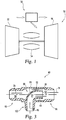
- FIG. 2 One form of the working fluid system 58 is shown in FIG. 2 and includes a splitter 60 that is shown as receiving a top side flow of lubricant 62 and splitting it to a right side flow of lubricant 64 and a bottom side of lubricant 66.
- a splitter 60 that is shown as receiving a top side flow of lubricant 62 and splitting it to a right side flow of lubricant 64 and a bottom side of lubricant 66.
- the terms “top”, “bottom”, “left”, and “right” are used for ease of reference and convenience only to distinguish the separate flows of lubricant as depicted in the illustrated embodiment of the FIG. 2 , but no limitation is hereby intended as to an orientation that may be used in a physical embodiment.
- An embodiment of the splitter 60 will be shown below in FIG. 3 .
- working fluid can be provided by the system 58 to any number of components, structures, accessories, etc of or connected with the gas turbine engine 50.
- working fluid is provided to a left side component 68 and a right side component 70.
- the left side component 68 can represent a gas turbine engine core section and the working fluid a lubricant such as oil for the core section.
- the lubricant can be used in an area radially inward of a flow path of the core section to assist components that are moving relative to each other such as bearings, etc.
- the passageway(s) that the working fluid will flow through the core section can be circuitous and can be defined by various structures of the core section.
- a sump can be used in the core section to collect the lubricant either before or after dispersal through the core section.
- the right side component 70 can represent another portion of the gas turbine engine and in some embodiments can represent an auxiliary gear box driven by work extracted from the gas turbine engine.
- the lubricant can also be used to assist in facilitating relative movement of parts in the accessory gear box.
- the passageway(s) that the working fluid will flow through the gear box can be defined by various structures.
- a reservoir can be used in some embodiments to collect the lubricant.
- a filter 72 can be used to recondition the working fluid and remove particulates that may be in the working fluid.
- the filter 72 can take a variety of forms such as a media based filter and a centrifugal type filter, among potential others.
- the filter 72 is depicted as a single block in the illustrated embodiment but additional filters arranged in series and/or in parallel can also be used.
- the filter 72 can be a scavenge oil filter for the gas turbine engine 50.
- the filter 72 can provide working fluid to a fluid mover 74 that assists in propelling the working fluid in the system 58.
- the fluid mover 74 can take a variety of forms such as a reciprocating pump, compressor, hydraulic pump, etc.
- the fluid mover 74 can be capable of providing working fluid at a variety of pressures and flow rates.
- FIG. 3 one embodiment of the splitter 60 is shown depicting an internal view and illustrates the embodiment providing internal flow passageways such that a right side flow 76 is split to form a left side flow 78 and a bottom flow 80.
- the illustrated embodiment in the figure depicts a "T" configuration in which the arms of the splitter 60 are shaped at right angles in the form of a T, but other embodiments can take on other configurations. For example, some embodiments can more closely resemble a Y-shape, while still further embodiments take on other shapes having arms that do not readily resemble a character from the alphabet.
- the splitter 60 includes right side passage 82 that receives the right side flow 76 and that leads to a scoop 84 used to receive a portion of the right side flow 76.
- the portion of lubricant not received in the scoop 84 is routed out of the splitter 60 through the left side passage 86.
- the scoop 84 can be used to receive any proportion of the right side flow 76. In some forms the proportions received in the scoop 84 and to the left side passage 86 can be substantially the same, but other embodiments can include other proportions.
- the scoop 84 includes a scoop passage 87 that is oriented to turn the lubricant to a different direction than the direction of the right side flow 76 and in the illustrated form includes a turned section 88 that is curved intermediate the ends depicted in the figure.
- the scoop passage 87 and/or turned section 88 can have any number of cross sectional shapes and associated wall geometries.
- the geometry of the upper wall is a constant radius curve, but in other forms the wall can include variable radius curves, piecewise linear walls, and any assortment of other types.
- the cross sectional shape of the scoop passage 87 can vary along the length of the scoop 84.
- the scoop passage 87 is generally circular in cross sectional shape between its ends, but in other forms the cross section can take on other shapes.
- the cross sectional shape can be curved such as ellipsoidal, can be faceted such as but not limited to square, triangular, or can be an arbitrary shape having a combination of curved and faceted surfaces, to set forth just a few nonlimiting embodiments.
- the shape can also vary over the length of the scoop 84.
- the scoop 84 is shown having an inlet 90 that is offset from internal walls of the splitter 60.
- the inlet 90 can be equally offset from a top wall 92 and a bottom wall 94, but not all embodiments need be equally spaced.
- the spacing of the inlet 90 relative to the internal walls can also be equidistant.
- the inlet 90 can be biased toward an internal wall of the splitter 60.
- the inlet 90 can be biased toward the bottom wall 94 in some forms
- the wall of the scoop 84 that forms one or more sides of the scoop passage 87 can have any variety of dimensions and in the illustrated form is shown having a constant thickness. In some forms the wall of the scoop 84 can have varying thickness dependent upon its location. For example, the thickness can be smaller near the inlet 90 and grow increasingly thick in some forms, while in others the thickness can be relatively large near the inlet 90 and grow progressively thinner along a length of the scoop passage 87.
- the leading edge of the inlet to the scoop can have a chamfered end as shown in the illustrated embodiment.
- Some forms of the inlet can include other shapes, such as a blunt curved shape, a blunt right angle shape, along with any number of others.
- the inlet can be located in a plane that is presented at a right angle to the stream of lubricant, as shown in the illustrated embodiment, but in other forms the inlet can be located in a plane formed at an angle.
- the top portion of the inlet can be set back further downstream than the bottom portion of the inlet, thus forming an inlet that is shaped as having a cut that falls from the upper left to the lower right of the figure.
- the leading edge of the inlet can have a variety of shapes that are not confined to a plane. Any variety of other shapes and configurations of the leading edge of the inlet are also contemplated.
- the internal through-passage of the splitter 60 that extends between the ends of the illustrated splitter and that includes the right side passage 82 and the left side passage 86 is configured as circular in cross sectional shape.
- the area of the internal through passage can change as it extends between the ends of the illustrated splitter.
- the internal through-passage includes step out in an internal wall shown at the top and bottom of the figure in the axial location region where the scoop 84 is located.
- a step out can correspond to an increase in cross sectional area of the through-passage in the area where the scoop 84 is located to account for a decrease in effective cross sectional area owing to the presence of the walls of the scoop passage 87.
- the cross sectional area may not change in other embodiments where the step out does not extend around the entire inner periphery of the through-passage.
- a side wall (not shown) may include a step-in to offset, or partially offset, a step out as shown in the upper and lower portions of the through-passage.
- the step-out, furthermore, on the upstream side can be different than the step-out on the downstream side, as is reflected in the illustrated embodiment. Some forms, however, may be the same.
- the splitter 60 can include provisions 96, 98, and 100 that permit the splitter 60 to be connected on the left side, right side, and bottom to passageway couplings, such as but not limited to hose couplings. Such couplings can be of a quick connect variety, but can take on other forms such as but not limited to threaded couplings. These and other variations are contemplated herein to permit the splitter 60 to be coupled with passageways such as hoses.
- FIG. 4 another embodiment of a working fluid system is shown.
- the embodiment of FIG. 4 locates a fluid tank, or fluid reservoir, (denoted as "FLUID RES" in the illustration) upstream from the flow splitter 60 and oriented to receive flow from the filter 72.
- the splitter 60 is used to split flow from the fluid tank, or fluid reservoir, and route it to fluid mover 74A on a left side, and a fluid mover 74B on the right side.
- the fluid movers 74A and 74B move fluid to their respective components 68 and 70.
- the fluid tank, or fluid reservoir is configured at a height above the splitter 60 such that fluid is fed to the splitter 60 via gravity.
- any of various heights can be used to provide an appropriate gravity feed for the splitter 60.
- similar reference numerals refer to similar features between the various illustrations.
- the fluid movers 74A and 74B will be appreciated as being similar to fluid mover 74. Accordingly, the fluid movers 74A and 74B can take a variety of forms such as a reciprocating pump, compressor, hydraulic pump, etc.
- an apparatus comprising a gas turbine engine having a rotatable turbomachinery that includes a compressor and turbine, the gas turbine engine also having a combustor structured to mix a fuel with a compressed working fluid received from the compressor and combust the mixture, the gas turbine engine having a mechanical device that includes a utility fluid receiving portion, a conduit carrying the utility fluid and in fluid communication with the mechanical device, a utility fluid flow splitter having a circular cross sectional shape configured to receive the utility working fluid and structured to receive a utility working fluid flowing in a bulk fluid direction and direct the utility working fluid into a first split passage and a second split passage, the utility fluid flow splitter having a scoop wall member disposed within the splitter to split the utility working fluid into a first split flow to traverse the first split passage and a second split flow to traverse the second split passage, a first split conduit configured to receive the first split flow from the utility fluid flow splitter, and a second split conduit configured to receive the second split flow from the
- the second split passage includes a turn downstream of the upstream end of the scoop wall member, the turn oriented to provide a direction of the utility working fluid in the second split passage different than the bulk fluid direction.
- the scoop wall member is an annular member. The scoop wall member is disposed such that the utility working fluid flows around the entire periphery of the annular member.
- the first split passage provides a direction of the utility working fluid in substantially the same direction of the bulk fluid direction, and wherein the direction of the utility working fluid in the second split passage forms one of a T and a Y with the bulk fluid direction and the direction of utility working fluid in the first split passage.
- Yet another feature of the present application provides wherein the turn in the second split passage is curvilinear to discourage flow recirculation or separation areas, and which further includes a pump in fluid communication with the utility fluid flow splitter.
- Still another feature of the present application provides wherein the pump is located downstream of the utility fluid flow splitter, and wherein the mechanical device is one of a power section component of the gas turbine engine and a gearbox.
- scoop wall member presents an arcuate protrusion to a bulk flow as viewed from the bulk fluid direction.
- a feature of the present application provides wherein the second conduit includes a turn along a flow direction.
- Another feature of the present application provides wherein the turn forms one of a Y and a T with the feed conduit and the first conduit.
- Still another feature of the present application provides wherein the turn includes a smoothly changing shape structured to minimize fluid flow phenomena that decrease fluid flow efficiency, and wherein the curvilinear first lateral flow surface is disposed radially outward of the curvilinear second lateral flow surface.
- fluid flow phenomena is one of flow separation and recirculation zones, and wherein the curvilinear second lateral flow surface is annular.
- Still yet another feature of the present application provides wherein the curvilinear first lateral flow surface encircles the curvilinear second lateral flow surface.
- a further feature of the present application provides wherein the curvilinear first lateral flow surface is concave and wherein a wall disposed interior to the curvilinear first lateral flow surface includes a portion forming the curvilinear second lateral flow surface.
- Yet another aspect of the present application provides an apparatus comprising a gas turbine engine having a flow path for air through a compressor, combustor, and a turbine, the air mixed with fuel and combusted prior to being expanded in the turbine to provide power, the gas turbine engine also having a mechanism that utilizes a utility fluid to provide one of lubrication and heat transfer, a utility fluid system having a first conduit, second conduit, and third conduit carrying the utility fluid, and means for scooping the utility fluid from the first conduit and portioning the utility fluid to the second conduit and to the third conduit.
- a feature of the present application further includes means for discouraging the formation of adverse fluid flow phenomena.
- a further aspect of the present application provides a method for splitting flow streams comprising rotating a bladed component in a gas turbine engine to alter a pressure of a working fluid therein, delivering a lubricant to the bladed component from a lubrication circulation system, flowing the lubricant through a supply line to a flow split device comprising a scoop wall member wherein the scoop wall member is an annular member and is disposed such that the lubricant flows around the entire periphery of the annular member, dividing the flow of lubricant on either side of a flow member disposed within the flow split device and that extends upstream into the flow of lubricant, and delivering a first divided flow of lubricant out of the flow split device to a first downstream line and a second divided flow of lubricant out of the flow split device to a second downstream line.
- a feature of the present application further includes routing the first divided flow around an outside portion of the second divided flow, wherein the flow member includes a curved shape.
- Another feature of the present application further includes forming an annulus of flow with the first divided flow.
- Yet another feature of the present application further includes turning the second divided flow into a direction different than a direction of a flow of lubricant from the supply line into the flow split device.
- Still another feature of the present application provides wherein the turning includes moving the lubricant along a surface involved in the turning that discourages formation of one of separation and flow recirculation.
- Yet still another feature of the present application provides wherein a direction of a flow of lubricant delivered to the first downstream line is substantially the same as a direction of the flow of lubricant in the supply line.
- Still yet another feature of the present application further includes providing the lubricant to one of a core power section of the gas turbine engine and a gearbox, and wherein a direction of a flow of lubricant delivered to the second downstream line is different than the direction of the flow of lubricant in the supply line.
- a further feature of the present application further includes forming an annular flow of lubricant as a result of the dividing.
Landscapes
- Engineering & Computer Science (AREA)
- General Engineering & Computer Science (AREA)
- Mechanical Engineering (AREA)
- Chemical & Material Sciences (AREA)
- Combustion & Propulsion (AREA)
- Structures Of Non-Positive Displacement Pumps (AREA)
Claims (13)
- Gerät, Folgendes beinhaltend:einen Gasturbinenmotor (50), welcher eine drehbare Turbomaschinerie besitzt, welche einen Kompressor (52) und eine Turbine (56) enthält, wobei der Gasturbinenmotor (50) ebenfalls einen Brenner (54) besitzt, welcher strukturiert ist, um Brennstoff mit einem komprimierten Arbeitsfluid zu mischen, welches vom Kompressor (52) aufgenommen wird, und die Mischung zu verbrennen, wobei der Gasturbinenmotor (50) eine mechanische Vorrichtung besitzt, welche einen Versorgungs-Arbeitsfluid aufnehmenden Abschnitt enthält.eine Leitung, welche das Versorgungs-Arbeitsfluid führt und in Fluidkommunikation mit der mechanischen Vorrichtung steht;einen Versorgungs-Arbeitsfluid Strömungsteiler (60), welcher einen kreisförmigen Querschnitt besitzt, welcher konfiguriert ist, um das Versorgungs-Arbeitsfluid von der Leitung aufzunehmen und strukturiert ist, um das Versorgungs-Arbeitsfluid, welches in einer Hauptfluidströmungsrichtung (76) strömt, aufzunehmen und das Versorgungs-Arbeitsfluid in einen ersten Teildurchgang (86) und einen zweiten Teildurchgang (87) zu leiten, wobei der Versorgungs-Arbeitsfluid-Strömungsteiler ein Löffel-Wandelement (84) besitzt, welches innerhalb des Teilers (60) angeordnet ist, um das Versorgungs-Arbeitsfluid in einen ersten Teilstrom zum Durchqueren des ersten Teilerdurchgangs (86) und einen zweiten Teilstrom zum Durchqueren des zweiten Teilerdurchgangs (87) zu teilen;eine erste Teilleitung, welche konfiguriert ist, um den ersten Teilstrom (78) vom Versorgungs-Arbeitsfluid-Strömungsteiler (60) aufzunehmen; undeine zweite Teilleitung, welche konfiguriert ist, um den zweiten Teilstrom (80) vom Versorgungs-Arbeitsfluid-Strömungsteiler (60) aufzunehmen (60); wobei der zweite Teildurchgang eine Biegung im nachgelagerten Bereich des vorgelagerten Endes des Löffel-Wandelementes (84) besitzt, wobei die Biegung ausgerichtet ist, um eine Richtung des Versorgungs-Arbeitsfluids in dem zweiten Teildurchgang (87) bereitzustellen, welche sich von der Hauptfluidströmungsrichtung (76) unterscheidet; und wobei das Löffel-Wandelement (84) ein ringförmiges Element ist; wobei das Löffel-Wandelement (84) so angeordnet ist, dass das Versorgungs-Arbeitsfluid rund um den gesamten Umfang des ringförmigen Elementes strömt.
- Gerät nach Anspruch 1, bei welchem der erste Teildurchgang (86) eine Richtung des Versorgungs-Arbeitsfluids bereitstellt in im Wesentlichen derselben Richtung wie die Hauptfluidströmungsrichtung (76), und wobei die Richtung des Versorgungs-Arbeitsfluids in dem zweiten Teildurchgang (87) eines von einem T und einem Y, mit der Hauptfluidströmungsrichtung (76) und der Richtung des Versorgungs-Arbeitsfluids in dem ersten Teildurchgang (86) bildet.
- Gerät nach Anspruch 1, bei welchem die Biegung im zweiten Teildurchgang (87) kurvenförmig ist, um Bereiche mit Strömungsrückführung oder -trennung zu vermeiden, und welches zudem eine Pumpe in Fluidkommunikation mit dem Versorgungsfluid-Strömungsteiler (60) enthält; wobei optionsweise die Pumpe im nachgelagerten Bereich des Versorgungsfluid-Strömungsteilers (60) befindlich ist, und wobei die mechanische Vorrichtung eines von einem Leistungsabschnitt des Gasturbinenmotors (50) und einem Getriebe ist.
- Gerät nach Anspruch 1, bei welchem das Löffel-Wandelement (84) einen bogenförmigen Vorsprung zu einer Hauptfluidströmungsrichtung aufweist, wenn es aus der Hauptfluidströmungsrichtung betrachtet wird.
- Gerät nach Anspruch 1, bei welchem der Gasturbinenmotor (50) einen Einlass für die Zufuhr von Luft an einen Kompressor (52) besitzt, wobei der Brenner (54) betreibbar ist, um eine Mischung von Brennstoff und Luft, welche vom Kompressor (52) komprimiert wird, zu verbrennen, wobei der Gasturbinenmotor (50) ebenfalls eine Turbine (56) besitzt, welche strukturiert ist, um einen Strömungsfluss zu expandieren, welcher vom Brenner (54) abgegeben wird; wobei das Versorgungsfluid ein Schmiermittel ist, welches mit der mechanischen Vorrichtung verwendet werden soll, welche vom Schmiermittel geschmierte Bauteile besitzt;
ein Schmiersystem (58), welches eine Vielzahl von Leitungen zum Durchleiten des Schmiermittels besitzt, wobei die Vielzahl von Leitungen eine Speiseleitung enthält, welche dem Versorgungsfluid-Strömungsteiler (60) Schmiermittel bereitstellt, welcher eine Strömungsunterteilung beinhaltet, und wobei die Strömungsunterteilung Schmiermittel an den ersten Teildurchgang bereitstellt, welcher eine erste Leitung beinhaltet, und an einen zweiten Teildurchgang, welcher eine zweite Leitung beinhaltet, wobei die Strömungsunterteilung eine erste seitliche kurvenförmige Strömungsfläche besitzt, welche einen Abschnitt der ersten Leitung definiert, und eine zweite seitliche kurvenförmige Strömungsfläche besitzt, welche einen Abschnitt der zweiten Leitung definiert, wobei die erste seitliche kurvenförmige Strömungsfläche an einer gegenüberliegenden Seitenwand der Strömungsunterteilung von der zweiten seitlichen kurvenförmigen Strömungsfläche angeordnet ist. - Gerät nach Anspruch 5, bei welchem die zweite Leitung eine Biegung entlang einer Strömungsrichtung enthält.
- Gerät nach Anspruch 6, bei welchem:(i) die Biegung eines von einem Y und einem T mit der Speiseleitung und der ersten Leitung bildet; oder(ii) bei welchem die Biegung eine sich sanft verändernde Form enthält, welche strukturiert ist, um Fluidströmungsphänomene zu minimieren, welche die Fluidströmungseffizienz verringern, und wobei die erste seitliche kurvenförmige Strömungsfläche radial auswärts von der zweiten seitlichen kurvenförmigen Strömungsfläche angeordnet ist, wobei optionsweise die Fluidströmungsphänomene eines von Bereichen mit Strömungstrennung und -rückführung sind und wobei die zweite seitliche kurvenförmige Strömungsfläche ringförmig ist.
- Gerät nach Anspruch 5, bei welchem die erste seitliche kurvenförmige Strömungsfläche die zweite seitliche kurvenförmige Strömungsfläche umgreift.
- Gerät nach Anspruch 8, bei welchem die erste seitliche kurvenförmige Strömungsfläche konkav ist und bei welchem eine Wand, welche im Innern der ersten seitlichen kurvenförmigen Strömungsfläche angeordnet ist, einen Abschnitt enthält, welcher die zweite seitliche kurvenförmige Strömungsfläche bildet.
- Gerät nach Anspruch 1, bei welchem der Gasturbinenmotor (50) einen Strömungsweg für Luft durch den Kompressor (52), den Brenner (54) und die Turbine (56) besitzt, wobei die mit Brennstoff gemischte Luft, welche verbrannt wird, bevor sie in der Turbine (56) expandiert wird, um Leistung bereitzustellen, wobei der Gasturbinenmotor (50) ebenfalls einen Mechanismus besitzt, welcher das Versorgungsfluid nutzt, um eines von Schmierung und Wärmeübertragung bereitzustellen;
wobei ein Versorgungsfluidsystem eine erste Leitung, eine zweite Leitung und eine dritte Leitung besitzt, welche das Versorgungsfluid führen; und
Mittel, welche den Versorgungsfluid-Strömungsteiler beinhalten zum Abschöpfen des Versorgungsfluids aus der ersten Leitung und zum portionierten Zuführen des Versorgungsfluids an die zweite Leitung und die dritte Leitung. - Gerät nach Anspruch 10, welches zudem Mittel zum Vermeiden der Bildung von nachteiligen Fluidströmungsphänomenen enthält.
- Verfahren zum Teilen von Strömungsflüssen, welches Folgendes beinhaltet:Drehen eines mit Blättern versehenen Bauteils in einem Gasturbinenmotor (50) zum Verändern des Drucks eines Arbeitsfluids darin;Abgeben eines Schmiermittels an das mit Blättern versehene Bauteil aus einem Umlaufschmiersystem;Verströmen des Schmiermittels durch eine Speiseleitung zu einer Strömungsteilungsvorrichtung, welche ein Löffel-Wandelement (84) beinhaltet, wobei das Löffel-Wandelement (84) ein ringförmiges Element ist und so angeordnet ist, dass das Schmiermittel rund um den gesamten Umfang des ringförmigen Elementes strömt;Unterteilen des Schmiermittelstroms an beiden Seiten eines Strömungselementes, welches innerhalb der Strömungsteilungsvorrichtung angeordnet ist und welches sich im vorgelagerten Bereich in einen Schmiermittelstrom erstreckt; undAbgeben eines ersten unterteilten Schmiermittelstroms aus der Strömungsteilungsvorrichtung an eine erste nachgelagerte Leitung, und eines zweiten unterteilten Schmiermittelstroms aus der Strömungsteilungsvorrichtung an eine zweite nachgelagerte Leitung.
- Verfahren nach Anspruch 12, welches zudem Führen des ersten unterteilten Stroms um einen äußeren Abschnitt des zweiten unterteilten Stroms enthält, wobei das Strömungselement eine gebogene Form enthält; oder welches zudem Bilden eines ringförmigen Strömungsraums mit dem ersten unterteilten Strom enthält.
Applications Claiming Priority (2)
| Application Number | Priority Date | Filing Date | Title |
|---|---|---|---|
| US201161582270P | 2011-12-31 | 2011-12-31 | |
| PCT/US2012/072233 WO2013141942A1 (en) | 2011-12-31 | 2012-12-30 | Flow splitter for a fluid system of a gas turbine engine |
Publications (3)
| Publication Number | Publication Date |
|---|---|
| EP2798229A1 EP2798229A1 (de) | 2014-11-05 |
| EP2798229A4 EP2798229A4 (de) | 2015-09-16 |
| EP2798229B1 true EP2798229B1 (de) | 2019-04-17 |
Family
ID=49223152
Family Applications (1)
| Application Number | Title | Priority Date | Filing Date |
|---|---|---|---|
| EP12872022.4A Active EP2798229B1 (de) | 2011-12-31 | 2012-12-30 | Strömungsspalter für ein flüssigkeitssystem eines gasturbinenmotors |
Country Status (4)
| Country | Link |
|---|---|
| US (1) | US10260373B2 (de) |
| EP (1) | EP2798229B1 (de) |
| CA (1) | CA2862656C (de) |
| WO (1) | WO2013141942A1 (de) |
Families Citing this family (6)
| Publication number | Priority date | Publication date | Assignee | Title |
|---|---|---|---|---|
| US9989083B2 (en) | 2015-05-26 | 2018-06-05 | Pratt & Whitney Canada Corp. | Seal and bearing assembly for a gas turbine engine and method of assembling same |
| WO2017158636A1 (ja) * | 2016-03-14 | 2017-09-21 | 株式会社 東芝 | ガスタービン設備 |
| USD996960S1 (en) * | 2022-01-27 | 2023-08-29 | Mullet Tools, LLC | Adapter |
| US12089528B2 (en) | 2022-04-06 | 2024-09-17 | Cnh Industrial America Llc | Product flow splitter for an agricultural implement |
| US11867357B1 (en) * | 2022-09-09 | 2024-01-09 | Pratt & Whitney Canada Corp. | Deaeration conduit |
| US12590551B1 (en) * | 2024-09-25 | 2026-03-31 | Pratt & Whitney Canada Corp. | Oil tank return for an aircraft engine oil system |
Family Cites Families (43)
| Publication number | Priority date | Publication date | Assignee | Title |
|---|---|---|---|---|
| US598327A (en) * | 1898-02-01 | Water-heating system | ||
| US253908A (en) * | 1882-02-21 | Main for conveying fluids | ||
| US445090A (en) | 1891-01-20 | Of albany | ||
| US783586A (en) * | 1903-02-07 | 1905-02-28 | Henry J Luff | Wall clean-out and back-vent fitting. |
| US933279A (en) * | 1908-05-28 | 1909-09-07 | Lawrence E Welch | Waste-trap. |
| US1086143A (en) * | 1911-02-09 | 1914-02-03 | Nelson Mcclellan Davidson | Hot-water deflector. |
| US1586691A (en) * | 1923-02-06 | 1926-06-01 | Jr Thomas E Murray | Welding |
| FR625733A (fr) * | 1926-12-06 | 1927-08-18 | Bergische Stahlindustrie | Dispositif pour rendre inoffensive la pression en excès, aux points de jonction de conduites tubulaires |
| US2141797A (en) * | 1937-03-26 | 1938-12-27 | Minella Angelo | Fitting |
| US2164011A (en) * | 1937-05-13 | 1939-06-27 | Donald F Ainslee | Orchard heating system |
| US2304609A (en) * | 1941-12-01 | 1942-12-08 | Jasper D Stokes | Pipe fitting |
| US2939626A (en) | 1957-12-27 | 1960-06-07 | Laval Steam Turbine Co | Turbo-compressor |
| DE1286296B (de) | 1964-10-19 | 1969-01-02 | Fischer Rainer | Verfahren und Vorrichtung zum gleichzeitigen Beschicken von mindestens zwei Spritzkoepfen bei Kunststoffverarbeitungsmaschinen von einer Strangpresse aus |
| US3510156A (en) * | 1967-04-01 | 1970-05-05 | Karl Heinz Markowz | Device for transmitting flows |
| GB1210994A (en) * | 1969-05-15 | 1970-11-04 | Leonard Charles Harvey | Improvements in or relating to fittings for liquid circulation systems |
| DE2205180A1 (de) * | 1972-02-04 | 1973-08-09 | Georg Prof Dr Ing Hutarew | Abzweig- und beileitungsstueck einer rohrleitung |
| US4057371A (en) * | 1974-05-03 | 1977-11-08 | Norwalk-Turbo Inc. | Gas turbine driven high speed centrifugal compressor unit |
| US4020632A (en) * | 1975-07-17 | 1977-05-03 | The United States Of America As Represented By The United States National Aeronautics And Space Administration Office Of General Counsel-Code Gp | Oil cooling system for a gas turbine engine |
| GB2083879B (en) * | 1980-09-11 | 1984-01-25 | Ameron Inc | Fiber reinforced plastics pipe tee |
| US4446377A (en) * | 1982-05-03 | 1984-05-01 | General Electric Company | Low collapse speed lube oil pumping system for turbomachinery |
| US4473035A (en) * | 1982-08-18 | 1984-09-25 | Foster Wheeler Energy Corporation | Splitter-bifurcate arrangement for a vapor generating system utilizing angularly arranged furnace boundary wall fluid flow tubes |
| US4494567A (en) | 1983-04-08 | 1985-01-22 | Troyen Harry D | Apparatus for supplying a flow of liquid to a turbine |
| US4645415A (en) * | 1983-12-23 | 1987-02-24 | United Technologies Corporation | Air cooler for providing buffer air to a bearing compartment |
| US4578188A (en) * | 1985-07-26 | 1986-03-25 | Cousino Kenneth P | Sewerage flow diverter |
| US4729228A (en) * | 1986-10-20 | 1988-03-08 | American Standard Inc. | Suction line flow stream separator for parallel compressor arrangements |
| US5131807A (en) * | 1990-07-16 | 1992-07-21 | Allied-Signal Inc. | Reverse pitot air filter |
| US5322387A (en) * | 1992-06-08 | 1994-06-21 | Heine Robert S | Waste water drainfield |
| DE4403067C1 (de) | 1994-02-02 | 1995-04-06 | Deutsche Aerospace Airbus | Vorrichtung zum Eisfreihalten von einseitig offenen Flüssigkeitsleitungen |
| US6412820B1 (en) * | 1999-10-22 | 2002-07-02 | General Electric Company | Secured coupling assembly and method of preventing loosening |
| US6712080B1 (en) * | 2002-02-15 | 2004-03-30 | The United States Of America As Represented By The Secretary Of The Army | Flushing system for removing lubricant coking in gas turbine bearings |
| US6886324B1 (en) * | 2002-02-15 | 2005-05-03 | The United States Of America As Represented By The Secretary Of The Army | Apparatus for reducing coking in gas turbine bearings |
| US20050035592A1 (en) * | 2003-08-06 | 2005-02-17 | Williams Larry Franklin | Smooth flow pipe connector for lawn sprinkler system |
| US6976827B2 (en) * | 2003-10-14 | 2005-12-20 | Pratt & Whitney Canada Corp. | Rotor balancing device and method |
| US7174919B2 (en) * | 2003-10-20 | 2007-02-13 | Metaldyne Company, Llc | Flow redirection member and method of manufacture |
| US8091925B2 (en) * | 2008-02-22 | 2012-01-10 | Bulk Tank, Inc. | Fluted hopper tee |
| DE102009011635A1 (de) | 2009-03-04 | 2010-09-09 | Rolls-Royce Deutschland Ltd & Co Kg | Luftleitelement eines Laufspalteinstellungssystems einer Fluggasturbine |
| US8752673B2 (en) * | 2009-08-27 | 2014-06-17 | Pratt & Whitney Canada Corp. | Lubrication system with porous element |
| US8833086B2 (en) * | 2012-05-31 | 2014-09-16 | United Technologies Corporation | Lubrication arrangement for a gas turbine engine gear assembly |
| US9816897B2 (en) * | 2012-06-06 | 2017-11-14 | Harris Corporation | Wireless engine monitoring system and associated engine wireless sensor network |
| EP2801707B1 (de) * | 2013-05-10 | 2017-07-05 | Safran Aero Boosters SA | Schmierkreislauf eines Turbotriebwerks mit Überlaufventil für Windmilling |
| US9777698B2 (en) * | 2013-11-12 | 2017-10-03 | Daniel Keith Schlak | Multiple motor gas turbine engine system with auxiliary gas utilization |
| US9656756B2 (en) * | 2014-03-10 | 2017-05-23 | The Boeing Company | Turbo-compressor system and method for extracting energy from an aircraft engine |
| US10100748B2 (en) * | 2014-09-15 | 2018-10-16 | The Boeing Company | Dual fuel gas turbine thrust and power control |
-
2012
- 2012-12-30 EP EP12872022.4A patent/EP2798229B1/de active Active
- 2012-12-30 CA CA2862656A patent/CA2862656C/en not_active Expired - Fee Related
- 2012-12-30 WO PCT/US2012/072233 patent/WO2013141942A1/en not_active Ceased
-
2014
- 2014-06-30 US US14/319,961 patent/US10260373B2/en active Active
Non-Patent Citations (1)
| Title |
|---|
| None * |
Also Published As
| Publication number | Publication date |
|---|---|
| CA2862656C (en) | 2019-10-08 |
| EP2798229A1 (de) | 2014-11-05 |
| WO2013141942A1 (en) | 2013-09-26 |
| US20140311155A1 (en) | 2014-10-23 |
| EP2798229A4 (de) | 2015-09-16 |
| US10260373B2 (en) | 2019-04-16 |
| CA2862656A1 (en) | 2013-09-26 |
Similar Documents
| Publication | Publication Date | Title |
|---|---|---|
| EP2798229B1 (de) | Strömungsspalter für ein flüssigkeitssystem eines gasturbinenmotors | |
| EP3179075B1 (de) | Wärmeverwaltungssystem für gasturbine | |
| EP3081780B1 (de) | Schmiermittelkreislaufsystem und verfahren zur schmiermittelumwälzung in einem gasturbinenmotor | |
| EP3187724A1 (de) | Verfahren und system für kombinationswärmetauscher | |
| US20120159961A1 (en) | Gas turbine engine heat exchanger | |
| EP3633156B1 (de) | Ölwannenzusatzentlüftungssystem | |
| US7748209B1 (en) | Small single use gas turbine engine with oil-less bearing arrangement | |
| US10443663B2 (en) | Clutch coupled to gas turbine engine and method for cooling | |
| EP3088685A1 (de) | Wärmeverwaltungssystem und verfahren zur zirkulation von luft in einem gasturbinenmotor | |
| US11994257B2 (en) | Centrifugal de-aerator for aircraft engine | |
| EP3181816A1 (de) | Schaufelprofil für ein gasturbinenkraftwerk, zugehöriges herstellungsverfahren und bauteil | |
| EP3179057A1 (de) | Lagersumpfanordnung für einen gasturbinenmotor | |
| EP3260668A1 (de) | Schmiersystem mit mehreren schmierkreisläufen | |
| EP3929470B1 (de) | Getriebeanordnung für flugzeugtriebwerk mit schmiermittelspeichertaschen | |
| US10041375B2 (en) | Apparatus for oil collection and heat exchanging for turbine engines | |
| CN112443652B (zh) | 具有收集器的用于航空发动机的齿轮组件 | |
| US11542844B2 (en) | Integrated lubricating fluid filtering and metering device | |
| EP2964925B1 (de) | Wärmetauschersystem für ein gasturbinentriebwerk | |
| US9033108B2 (en) | Lubricant flow suppressor | |
| CA2862647C (en) | Flow merging device for a fluid system of a gas turbine engine | |
| US20180094543A1 (en) | Insert apparatus and system for oil nozzle boundary layer injection | |
| US12618362B2 (en) | Methods and apparatus to provide cross-diffuser bleed | |
| CN114658547B (zh) | 用于润滑包括润滑剂旁通管道的燃气涡轮发动机的部件的系统 | |
| US20260022656A1 (en) | Methods and apparatus to provide cross-diffuser bleed |
Legal Events
| Date | Code | Title | Description |
|---|---|---|---|
| PUAI | Public reference made under article 153(3) epc to a published international application that has entered the european phase |
Free format text: ORIGINAL CODE: 0009012 |
|
| 17P | Request for examination filed |
Effective date: 20140728 |
|
| AK | Designated contracting states |
Kind code of ref document: A1 Designated state(s): AL AT BE BG CH CY CZ DE DK EE ES FI FR GB GR HR HU IE IS IT LI LT LU LV MC MK MT NL NO PL PT RO RS SE SI SK SM TR |
|
| DAX | Request for extension of the european patent (deleted) | ||
| RA4 | Supplementary search report drawn up and despatched (corrected) |
Effective date: 20150819 |
|
| RIC1 | Information provided on ipc code assigned before grant |
Ipc: F02C 7/14 20060101ALI20150813BHEP Ipc: F02C 7/18 20060101ALI20150813BHEP Ipc: F15D 1/14 20060101AFI20150813BHEP |
|
| 17Q | First examination report despatched |
Effective date: 20160920 |
|
| STAA | Information on the status of an ep patent application or granted ep patent |
Free format text: STATUS: EXAMINATION IS IN PROGRESS |
|
| GRAP | Despatch of communication of intention to grant a patent |
Free format text: ORIGINAL CODE: EPIDOSNIGR1 |
|
| STAA | Information on the status of an ep patent application or granted ep patent |
Free format text: STATUS: GRANT OF PATENT IS INTENDED |
|
| RIC1 | Information provided on ipc code assigned before grant |
Ipc: F02C 7/14 20060101ALI20180927BHEP Ipc: F02C 7/22 20060101ALI20180927BHEP Ipc: F15D 1/14 20060101AFI20180927BHEP Ipc: F01D 25/18 20060101ALI20180927BHEP Ipc: F02C 7/18 20060101ALI20180927BHEP |
|
| INTG | Intention to grant announced |
Effective date: 20181026 |
|
| GRAJ | Information related to disapproval of communication of intention to grant by the applicant or resumption of examination proceedings by the epo deleted |
Free format text: ORIGINAL CODE: EPIDOSDIGR1 |
|
| STAA | Information on the status of an ep patent application or granted ep patent |
Free format text: STATUS: EXAMINATION IS IN PROGRESS |
|
| GRAR | Information related to intention to grant a patent recorded |
Free format text: ORIGINAL CODE: EPIDOSNIGR71 |
|
| GRAS | Grant fee paid |
Free format text: ORIGINAL CODE: EPIDOSNIGR3 |
|
| STAA | Information on the status of an ep patent application or granted ep patent |
Free format text: STATUS: GRANT OF PATENT IS INTENDED |
|
| GRAA | (expected) grant |
Free format text: ORIGINAL CODE: 0009210 |
|
| STAA | Information on the status of an ep patent application or granted ep patent |
Free format text: STATUS: THE PATENT HAS BEEN GRANTED |
|
| INTC | Intention to grant announced (deleted) | ||
| AK | Designated contracting states |
Kind code of ref document: B1 Designated state(s): AL AT BE BG CH CY CZ DE DK EE ES FI FR GB GR HR HU IE IS IT LI LT LU LV MC MK MT NL NO PL PT RO RS SE SI SK SM TR |
|
| INTG | Intention to grant announced |
Effective date: 20190308 |
|
| REG | Reference to a national code |
Ref country code: GB Ref legal event code: FG4D |
|
| REG | Reference to a national code |
Ref country code: CH Ref legal event code: EP |
|
| REG | Reference to a national code |
Ref country code: DE Ref legal event code: R096 Ref document number: 602012059211 Country of ref document: DE |
|
| REG | Reference to a national code |
Ref country code: AT Ref legal event code: REF Ref document number: 1121857 Country of ref document: AT Kind code of ref document: T Effective date: 20190515 Ref country code: IE Ref legal event code: FG4D |
|
| REG | Reference to a national code |
Ref country code: NL Ref legal event code: MP Effective date: 20190417 |
|
| REG | Reference to a national code |
Ref country code: LT Ref legal event code: MG4D |
|
| PG25 | Lapsed in a contracting state [announced via postgrant information from national office to epo] |
Ref country code: NL Free format text: LAPSE BECAUSE OF FAILURE TO SUBMIT A TRANSLATION OF THE DESCRIPTION OR TO PAY THE FEE WITHIN THE PRESCRIBED TIME-LIMIT Effective date: 20190417 |
|
| PG25 | Lapsed in a contracting state [announced via postgrant information from national office to epo] |
Ref country code: ES Free format text: LAPSE BECAUSE OF FAILURE TO SUBMIT A TRANSLATION OF THE DESCRIPTION OR TO PAY THE FEE WITHIN THE PRESCRIBED TIME-LIMIT Effective date: 20190417 Ref country code: LT Free format text: LAPSE BECAUSE OF FAILURE TO SUBMIT A TRANSLATION OF THE DESCRIPTION OR TO PAY THE FEE WITHIN THE PRESCRIBED TIME-LIMIT Effective date: 20190417 Ref country code: FI Free format text: LAPSE BECAUSE OF FAILURE TO SUBMIT A TRANSLATION OF THE DESCRIPTION OR TO PAY THE FEE WITHIN THE PRESCRIBED TIME-LIMIT Effective date: 20190417 Ref country code: HR Free format text: LAPSE BECAUSE OF FAILURE TO SUBMIT A TRANSLATION OF THE DESCRIPTION OR TO PAY THE FEE WITHIN THE PRESCRIBED TIME-LIMIT Effective date: 20190417 Ref country code: SE Free format text: LAPSE BECAUSE OF FAILURE TO SUBMIT A TRANSLATION OF THE DESCRIPTION OR TO PAY THE FEE WITHIN THE PRESCRIBED TIME-LIMIT Effective date: 20190417 Ref country code: NO Free format text: LAPSE BECAUSE OF FAILURE TO SUBMIT A TRANSLATION OF THE DESCRIPTION OR TO PAY THE FEE WITHIN THE PRESCRIBED TIME-LIMIT Effective date: 20190717 Ref country code: AL Free format text: LAPSE BECAUSE OF FAILURE TO SUBMIT A TRANSLATION OF THE DESCRIPTION OR TO PAY THE FEE WITHIN THE PRESCRIBED TIME-LIMIT Effective date: 20190417 Ref country code: PT Free format text: LAPSE BECAUSE OF FAILURE TO SUBMIT A TRANSLATION OF THE DESCRIPTION OR TO PAY THE FEE WITHIN THE PRESCRIBED TIME-LIMIT Effective date: 20190817 |
|
| PG25 | Lapsed in a contracting state [announced via postgrant information from national office to epo] |
Ref country code: RS Free format text: LAPSE BECAUSE OF FAILURE TO SUBMIT A TRANSLATION OF THE DESCRIPTION OR TO PAY THE FEE WITHIN THE PRESCRIBED TIME-LIMIT Effective date: 20190417 Ref country code: LV Free format text: LAPSE BECAUSE OF FAILURE TO SUBMIT A TRANSLATION OF THE DESCRIPTION OR TO PAY THE FEE WITHIN THE PRESCRIBED TIME-LIMIT Effective date: 20190417 Ref country code: GR Free format text: LAPSE BECAUSE OF FAILURE TO SUBMIT A TRANSLATION OF THE DESCRIPTION OR TO PAY THE FEE WITHIN THE PRESCRIBED TIME-LIMIT Effective date: 20190718 Ref country code: PL Free format text: LAPSE BECAUSE OF FAILURE TO SUBMIT A TRANSLATION OF THE DESCRIPTION OR TO PAY THE FEE WITHIN THE PRESCRIBED TIME-LIMIT Effective date: 20190417 Ref country code: BG Free format text: LAPSE BECAUSE OF FAILURE TO SUBMIT A TRANSLATION OF THE DESCRIPTION OR TO PAY THE FEE WITHIN THE PRESCRIBED TIME-LIMIT Effective date: 20190717 |
|
| REG | Reference to a national code |
Ref country code: AT Ref legal event code: MK05 Ref document number: 1121857 Country of ref document: AT Kind code of ref document: T Effective date: 20190417 |
|
| PG25 | Lapsed in a contracting state [announced via postgrant information from national office to epo] |
Ref country code: IS Free format text: LAPSE BECAUSE OF FAILURE TO SUBMIT A TRANSLATION OF THE DESCRIPTION OR TO PAY THE FEE WITHIN THE PRESCRIBED TIME-LIMIT Effective date: 20190817 |
|
| REG | Reference to a national code |
Ref country code: DE Ref legal event code: R097 Ref document number: 602012059211 Country of ref document: DE |
|
| PG25 | Lapsed in a contracting state [announced via postgrant information from national office to epo] |
Ref country code: CZ Free format text: LAPSE BECAUSE OF FAILURE TO SUBMIT A TRANSLATION OF THE DESCRIPTION OR TO PAY THE FEE WITHIN THE PRESCRIBED TIME-LIMIT Effective date: 20190417 Ref country code: EE Free format text: LAPSE BECAUSE OF FAILURE TO SUBMIT A TRANSLATION OF THE DESCRIPTION OR TO PAY THE FEE WITHIN THE PRESCRIBED TIME-LIMIT Effective date: 20190417 Ref country code: RO Free format text: LAPSE BECAUSE OF FAILURE TO SUBMIT A TRANSLATION OF THE DESCRIPTION OR TO PAY THE FEE WITHIN THE PRESCRIBED TIME-LIMIT Effective date: 20190417 Ref country code: SK Free format text: LAPSE BECAUSE OF FAILURE TO SUBMIT A TRANSLATION OF THE DESCRIPTION OR TO PAY THE FEE WITHIN THE PRESCRIBED TIME-LIMIT Effective date: 20190417 Ref country code: DK Free format text: LAPSE BECAUSE OF FAILURE TO SUBMIT A TRANSLATION OF THE DESCRIPTION OR TO PAY THE FEE WITHIN THE PRESCRIBED TIME-LIMIT Effective date: 20190417 Ref country code: AT Free format text: LAPSE BECAUSE OF FAILURE TO SUBMIT A TRANSLATION OF THE DESCRIPTION OR TO PAY THE FEE WITHIN THE PRESCRIBED TIME-LIMIT Effective date: 20190417 |
|
| PLBE | No opposition filed within time limit |
Free format text: ORIGINAL CODE: 0009261 |
|
| STAA | Information on the status of an ep patent application or granted ep patent |
Free format text: STATUS: NO OPPOSITION FILED WITHIN TIME LIMIT |
|
| PG25 | Lapsed in a contracting state [announced via postgrant information from national office to epo] |
Ref country code: SM Free format text: LAPSE BECAUSE OF FAILURE TO SUBMIT A TRANSLATION OF THE DESCRIPTION OR TO PAY THE FEE WITHIN THE PRESCRIBED TIME-LIMIT Effective date: 20190417 Ref country code: IT Free format text: LAPSE BECAUSE OF FAILURE TO SUBMIT A TRANSLATION OF THE DESCRIPTION OR TO PAY THE FEE WITHIN THE PRESCRIBED TIME-LIMIT Effective date: 20190417 |
|
| 26N | No opposition filed |
Effective date: 20200120 |
|
| PG25 | Lapsed in a contracting state [announced via postgrant information from national office to epo] |
Ref country code: TR Free format text: LAPSE BECAUSE OF FAILURE TO SUBMIT A TRANSLATION OF THE DESCRIPTION OR TO PAY THE FEE WITHIN THE PRESCRIBED TIME-LIMIT Effective date: 20190417 |
|
| PG25 | Lapsed in a contracting state [announced via postgrant information from national office to epo] |
Ref country code: SI Free format text: LAPSE BECAUSE OF FAILURE TO SUBMIT A TRANSLATION OF THE DESCRIPTION OR TO PAY THE FEE WITHIN THE PRESCRIBED TIME-LIMIT Effective date: 20190417 |
|
| REG | Reference to a national code |
Ref country code: DE Ref legal event code: R119 Ref document number: 602012059211 Country of ref document: DE |
|
| REG | Reference to a national code |
Ref country code: CH Ref legal event code: PL |
|
| REG | Reference to a national code |
Ref country code: BE Ref legal event code: MM Effective date: 20191231 |
|
| PG25 | Lapsed in a contracting state [announced via postgrant information from national office to epo] |
Ref country code: MC Free format text: LAPSE BECAUSE OF FAILURE TO SUBMIT A TRANSLATION OF THE DESCRIPTION OR TO PAY THE FEE WITHIN THE PRESCRIBED TIME-LIMIT Effective date: 20190417 |
|
| GBPC | Gb: european patent ceased through non-payment of renewal fee |
Effective date: 20191230 |
|
| PG25 | Lapsed in a contracting state [announced via postgrant information from national office to epo] |
Ref country code: LU Free format text: LAPSE BECAUSE OF NON-PAYMENT OF DUE FEES Effective date: 20191230 Ref country code: IE Free format text: LAPSE BECAUSE OF NON-PAYMENT OF DUE FEES Effective date: 20191230 Ref country code: GB Free format text: LAPSE BECAUSE OF NON-PAYMENT OF DUE FEES Effective date: 20191230 Ref country code: DE Free format text: LAPSE BECAUSE OF NON-PAYMENT OF DUE FEES Effective date: 20200701 |
|
| PG25 | Lapsed in a contracting state [announced via postgrant information from national office to epo] |
Ref country code: BE Free format text: LAPSE BECAUSE OF NON-PAYMENT OF DUE FEES Effective date: 20191231 Ref country code: CH Free format text: LAPSE BECAUSE OF NON-PAYMENT OF DUE FEES Effective date: 20191231 Ref country code: LI Free format text: LAPSE BECAUSE OF NON-PAYMENT OF DUE FEES Effective date: 20191231 |
|
| PG25 | Lapsed in a contracting state [announced via postgrant information from national office to epo] |
Ref country code: CY Free format text: LAPSE BECAUSE OF FAILURE TO SUBMIT A TRANSLATION OF THE DESCRIPTION OR TO PAY THE FEE WITHIN THE PRESCRIBED TIME-LIMIT Effective date: 20190417 |
|
| PG25 | Lapsed in a contracting state [announced via postgrant information from national office to epo] |
Ref country code: HU Free format text: LAPSE BECAUSE OF FAILURE TO SUBMIT A TRANSLATION OF THE DESCRIPTION OR TO PAY THE FEE WITHIN THE PRESCRIBED TIME-LIMIT; INVALID AB INITIO Effective date: 20121230 Ref country code: MT Free format text: LAPSE BECAUSE OF FAILURE TO SUBMIT A TRANSLATION OF THE DESCRIPTION OR TO PAY THE FEE WITHIN THE PRESCRIBED TIME-LIMIT Effective date: 20190417 |
|
| PG25 | Lapsed in a contracting state [announced via postgrant information from national office to epo] |
Ref country code: MK Free format text: LAPSE BECAUSE OF FAILURE TO SUBMIT A TRANSLATION OF THE DESCRIPTION OR TO PAY THE FEE WITHIN THE PRESCRIBED TIME-LIMIT Effective date: 20190417 |
|
| P01 | Opt-out of the competence of the unified patent court (upc) registered |
Effective date: 20230528 |
|
| PGFP | Annual fee paid to national office [announced via postgrant information from national office to epo] |
Ref country code: FR Payment date: 20251230 Year of fee payment: 14 |